
1 ITEMVIEW CART

Total: 10.00

Expert Support
Full Speed
100% Working
100 USD
Contents:
1 General information
1.1 Safety regulations
1.2 Special tools for maintenance and repair work
2 Product description
2.1 Technical data
3 Maintenance
3.1 Maintenance and inspection schedule
3.2 Testing and adjustment schedule
3.3 Testing and adjustment protocol
3.4 Lubricant chart, filing quantities
3.5 Maintenance tasks
3.6 Testing and adjustment tasks
3.7 Lubricants and fuels
4 Diesel engine, pump distributor gear
4.1 Diesel engine
4.2 Fuel system
4.3 Air filter system
4.4 Coupling
4.5 Pump distributor gear
5 Cooling system
5.0 Cooling system
5.1 Gear pump
5.2 Gear motor
5.3 Temperature sensor
6 Travel hydraulics
6.0.1 Travel hydraulics L544, L554
6.0.2 Travel hydraulics L564 – L580
6.1 Variable displacement pump
6.2 Variable displacement motors
7 Working hydraulics
7.0.1 Working hydraulics L544, L554 to 11597
7.0.2 Working hydraulics L544, L554 to 11598
7.0.3 Working hydraulics L564, L574, L580 to 11597
7.0.4 Working hydraulics L564, L574, L580 to 11598
7.1 Working hydraulics pump
7.2 Control block
7.3 Pilot control unit
7.4 Ride control L544, L554 to 11597
7.5 Ride control L544, L554 to 11598
7.6 Ride control L564, L574, L580 to 11597
7.7 Ride control L564, L574, L580 to 11598
7.8 Lift and tilt cylinders
7.9 Hydraulic tank
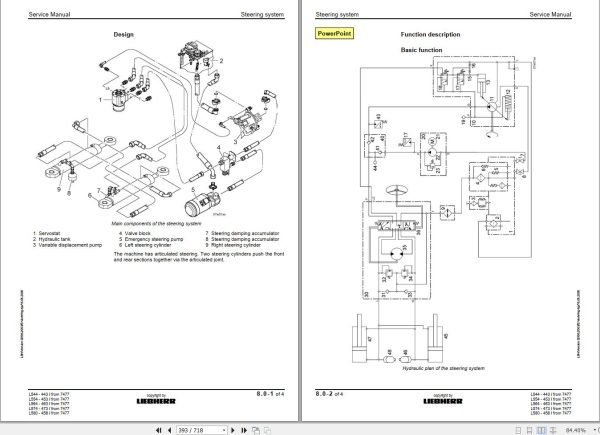
8 Steering system
8.0 Steering system
8.1 Steering pump
8.2 Servostat
8.3 Steering cylinder
8.4 Emergency steering
9 Brake system
9.0.1 Brake system
9.0.2 Brake system
9.1 Service brake
9.2 Parking brake
9.3 Overspeed protection
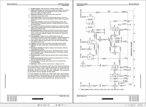
10 Electrical system
Circuit diagrams valid for Ser. No. 7477 – 9239
Circuit diagrams valid for Ser. No. 9240 – 9970
Circuit diagrams valid from Ser. No. 9971
10.0.1 Electrical system with circuit diagrams Valid for Ser. No. 7477 – 9239
10.0.2 Electrical system with circuit diagrams Valid from Ser. No. 9240
10.1 Main electronics
10.2 Control electronics (CPU) A1
10.3 Power electronics A12
10.4 Microcontroller A2 (MC6)
10.5 Battery installation
11 Transfer gear
11.0 Transfer gear
11.1 Mechanical transfer gear
11.2 Electronic control unit
11.3 Hydraulic control unit
12 Axles, drive shafts
12.1 Axle L544
12.2 Axles L554 – L580
12.3 Drive shafts
13 Machine frame, ballast weight
13.1 Machine frame
13.2 Articulation bearing
13.3 Oscillating axle mount
13.4 Articulation lock
13.5 Ballast weight
14 Central lubrication system
14.1 Manual central lubrication
14.2 Automatic central lubrication system
15 Covering, cab access
15.1 Covering
15.2 Cab access
16 Cab, heating, air-conditioning
16.0.1 Cab, heating, air-conditioning
16.1 Control panel
16.2 Heating, ventilation
16.3 Air-conditioning system
17 Lift arm, quick-change device
17.1 Lift arms
17.2 Pin and bush bearing
17.3 Quick-change device (Option)
18 Attachment, accessories
18.1 Connection dimensions
18.2 Bucket
18.3 Forklift
19 Repair work, troubleshooting
19.1 Malfunctions
19.2 Adjustments using the BODEM software
19.3 Troubleshooting for the 2plus2 transfer gear

REALEASE :
23.03.2022
REALEASE :
23.03.2022
REALEASE :
01.13.2022

REALEASE :
25.03.2022
REALEASE :
25.03.2022

REALEASE :
29.03.2022
REALEASE :
29.03.2022

REALEASE :
02.03.2022
REALEASE :
02.03.2022

REALEASE :
02.03.2022
REALEASE :
02.03.2022

REALEASE :
04.07.2022
REALEASE :
04.07.2022

REALEASE :
16.09.2022
REALEASE :
16.09.2022
Automotive - Heavy Equipment - Truck & Bus - Forklift - Crane