
2 ITEMSVIEW CART


Total: 55.00
Expert Support
Full Speed
100% Working
100 USD
Contents:
1 General
1.01 Instroduction
2 Accident prevention
2.02 Accident Prevention Guidelines
3 Tables, Data
3.01 Conversion Chart
3.02 Tightening Torques
3.03 ISO-Toleranzen
3.04 Material Classification
4 Special tools
4.01 General special Tools for Wheel loader
4.02 Special Tools for LIEBHERR Engine
4.04 Special Tools for electric
4.06 Special Tools for ZF – Axles
4.08 Special Tools for ZF – Powershift transmission
5 Welding
5.02 Repair Welding
6 Lubricants
6.01 Lubrication Chart – General
6.11 Lubrication chart
7 Specifications / Inspection plan
7.02 Adjustment Checklist
7.08 Technical Data
7.18 Inspection Schedule
7.25 Traction diagram
7.30 Maintenance and Inspections
8 Diesel Engine / Clutch
8.05 Liebherr Engine D 906 TI / D 916 TI
8.20 Solenoid / Engine shut off
8.30 Clutch
9 Pump Distributor Gear
9.10 Description and drawing of the gear box
10 Travelling hydraulic
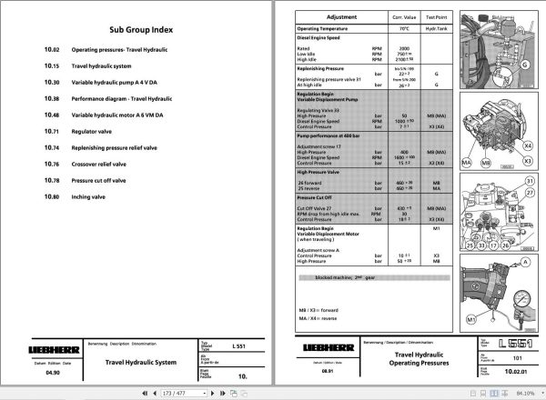
10.02 Operating pressures – Travel Hydraulic
10.15 Travel hydraulic system
10.30 Variable hydraulic pump A4V DA
10.38 Performance diagram – Travel Hydraulic
10.48 Variable hydraulic motor A6VM DA
10.71 Regulator valve
10.74 Replenishing pressure relief valve
10.76 Crossover relief valve
10.78 Pressure cut off valve
10.80 Inching valve
11 Working hydraulic
11.02 Operating Pressures
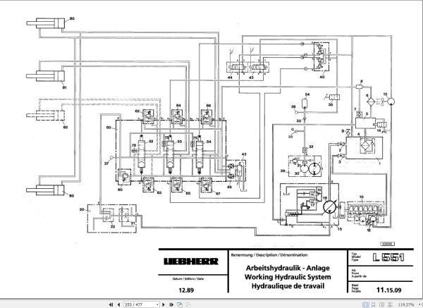
11.15 Working Hydraulic System
11.28 Variable Displacement Pump
11.38 Pump Performance Diagram
11.50 Control Valve – General Information – Leak Oil Data
11.53 Control Valve NG 22
11.68 Relief Valve
11.70 Thermostat Valve
11.81 Pilot (Servo) Control
11.84 Pilot Control Valve
11.90 Hydraulic Cylinder
12 Electrical System
12.15 Electrical Sytem
12.20 Instrument / Tachometer / Diode board / Relay / Fuses
13 Heater / Air conditioning
13.05 Heating and Ventilation System
14 Transmission
14.15 Powershift transmission 3 AVG 310
14.16 Troubleshooting
14.20 Electronic control
14.30 Bypass – Valve
14.35 Shifting Unit 3AVG 310
15 Axles / Tires
15.05 Differential
15.10 Differential
16 Steering
16.01 General Data
16.10 Hydraulic steering system
16.20 Valve Block
16.30 Servostat
16.40 Servostat Valve
16.50 Steering Cylinder
17 Brakes
17.01 General Information
17.15 Hydraulic Brake System
17.20 Cut Off Valve
17.30 Service Brake Valve
17.40 Parking Brake Valve
18 Main frame / Operator´s cab
18.10 Description of Removal / Installation of Articulation and Oscillating Axle
18.20 Description and Construction of Cab
19 Lift frame / Accessories
19.01 Lift Arms

REALEASE :
02.03.2022
REALEASE :
02.03.2022
REALEASE :
01.13.2022

REALEASE :
16.09.2022
REALEASE :
16.09.2022

REALEASE :
02.03.2022
REALEASE :
02.03.2022

REALEASE :
25.03.2022
REALEASE :
25.03.2022

REALEASE :
04.07.2022
REALEASE :
04.07.2022

REALEASE :
29.03.2022
REALEASE :
29.03.2022

REALEASE :
23.03.2022
REALEASE :
23.03.2022
 Automotive - Heavy Equipment - Truck & Bus - Forklift - Crane