
10 ITEMSVIEW CART


Total: 670.00


Expert Support
Full Speed
100% Working
30 USD
Contents:
6 Circuit Diagrams For The N20l/N20li/N20lol From 03/2018
6.1 Electric Circuit Diagrams
Power Circuit Diagram
Electric Circuit Diagram For N20l Control (With Slow Reverse Travel 1s13 And 1s14)
Electric Circuit Diagram For N20li Control (With Slow Reverse Travel 1s13 And 1s14)
Electric Circuit Diagram For N20lol Control
6.2 Options Circuit Diagrams
LithiumÂIon Battery Option
LithiumÂIon Battery Option (Power Pack)
LithiumÂIon Option (Side Access Charger)
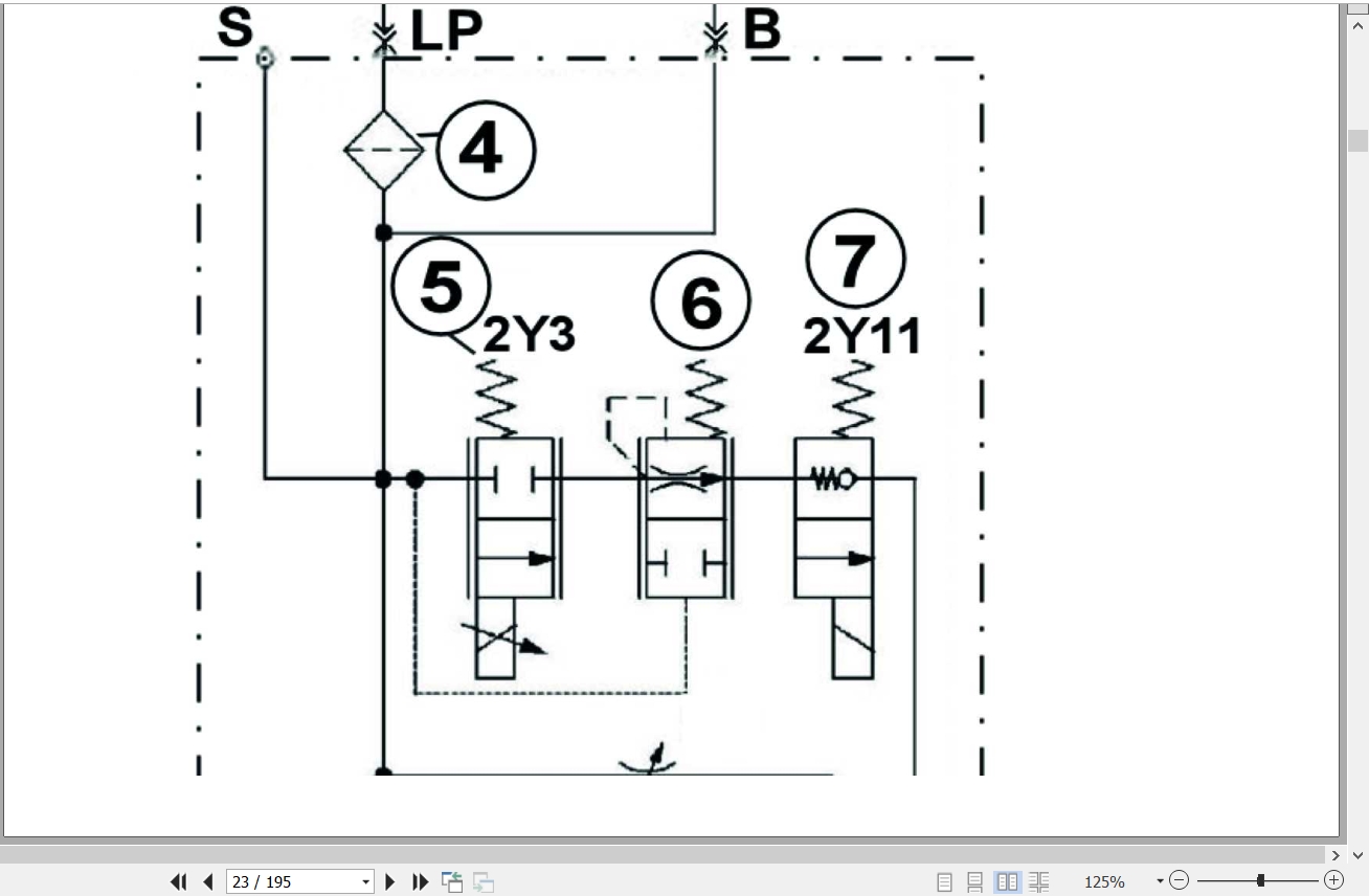
6.3 Hydraulic Circuit Diagrams
Without Initial Lift
With Initial Lift
5 Circuit Diagrams For The N20l/N20li From 01/2017 To 03/2018
5.1 Electric Circuit Diagrams
Power Circuit Diagram
Electric Circuit Diagram For N20l Control (With Slow Reverse Travel 1s13 And 1s14)
Electric Circuit Diagram For N20li Control (With Slow Reverse Travel 1s13 And 1s14)
5.2 Hydraulic Circuit Diagrams
Without Initial Lift
With Initial Lift
4 Circuit Diagrams For The N20l/N20li From 04/2015 (W4x132f01598) To 01/2017
4.1 Electric Circuit Diagrams
Power Electric Circuit Diagram (Steering Controller Es30Â24)
Electric Circuit Diagram N20l (Steering Controller Es30Â24)
Electric Circuit Diagram N20li (Steering Controller Es30Â24)
4.2 Hydraulic Circuit Diagrams
Without Initial Lift
With Initial Lift
3 Circuit Diagrams For The N20l/N20li From 03/2012 To 04/2015 (W4x132f01597)
3.1 Electric Circuit Diagrams
Power Electric Circuit Diagram (Without Brush Wear Detection)
Electric Circuit Diagram N20l (Without Reverse Travel Inching Mode Button 1s13 And 1s14)
Electric Circuit Diagram N20li (Without Reverse Travel Inching Mode Button 1s13 And 1s14)
3.2 Hydraulic Circuit Diagrams
Without Initial Lift
With Initial Lift
2 Circuit Diagrams For The N20l/N20li From 04/2010 To 03/2012
2.1 Electric Circuit Diagrams
Power Electric Circuit Diagram (Without Brush Wear Detection)Electric Circuit Diagram N20l (Without Brush Wear Detection)
Electric Circuit Diagram N20li (Without Brush Wear Detection)
2.2 Hydraulic Circuit Diagrams
Without Initial Lift
With Initial Lift
1 Circuit Diagrams For The N20l/N20li Up To 04/2010
1.1 Electric Circuit Diagrams
Power Wiring Diagram N20l  N20li
Wiring Diagram For Controls N20l
Wiring Diagram For Controls, N20li (Lac)
1.2 Hydraulic Circuit Diagrams
Without Initial Lift
With Initial Lift

REALEASE :
REALEASE :
REALEASE :

REALEASE :
12.04.2019
REALEASE :
12.04.2019

REALEASE :
12.4.2019
REALEASE :
12.4.2019
REALEASE :
07.10.2019
REALEASE :
07.10.2019

REALEASE :
07.10.2019
REALEASE :
07.10.2019

REALEASE :
30.09.2020
REALEASE :
30.09.2020

REALEASE :
07.10.2019
REALEASE :
07.10.2019
 Automotive - Heavy Equipment - Truck & Bus - Forklift - Crane