
0 ITEMSVIEW CART


✓
Expert Support
✓
Full Speed
✓
100% Working
Linde Pallet Stacker D1173-01 D12 D12AP D14 D14AP Electrical Hydraulic Diagrams 11738013601 2024
Size: 23.22 MB
Format: PDF
Language: English
Brand: Linde
Type of Machine: Pallet Stacker
Type of Manual: Electrical Diagrams, Hydraulic Diagrams
Model: Linde Series D1173-01 Pallet Stacker
L14-01, L16-01, L20-01
L14AP-01, L16AP-01, L20AP-01
L14AS-01, L16AS-01
L14ASAP-01, L16ASAP-01
D12-01, D14-01, D12AP-01, D14AP-01
Serial Number: W41173V04922, P21173V00001
Part Number: 11738013601
Publication Date: 2024
Number of Pages: 161 Pages
50 USD
- Description
Description
Contents:
6 Circuit Diagrams From 05/2020
6.1 Electric Circuit Diagrams
Power
Ap Control With Initial Lift
Control With Initial Lift
Ap Control Without Initial Lift
Control Without Initial Lift
6.2 Options Circuit Diagrams
Connect: And Electronic Key Options (Lku)
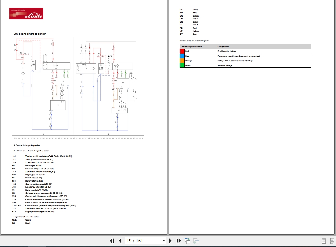
OnÂBoard Charger Option
LithiumÂIon Battery Option
LithiumÂIon Option (Side Access Charger)
Height Sensor Option
6.3 Hydraulic Circuit Diagrams
Without Initial Lift
With Initial Lift
Without Initial Lift/Booster Option
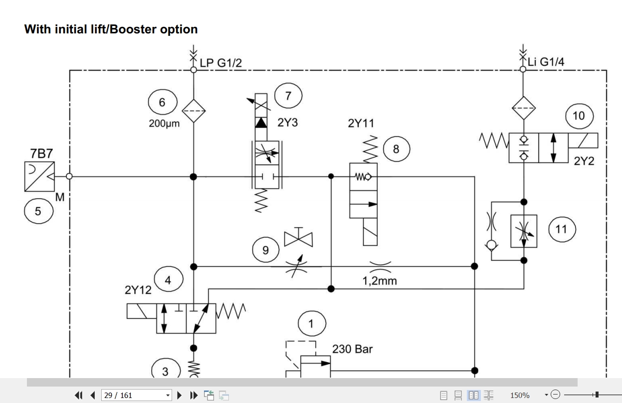
With Initial Lift/Booster Option
Line Break Safety Valves
5 Circuit Diagrams From 03/2019 (W41173v01289) To 05/2020
5.1 Electric Circuit Diagrams
Power
Ap Control With Initial Lift
Control With Initial Lift
Ap Control Without Initial Lift
Control Without Initial Lift
5.2 Options Circuit Diagrams
LithiumÂIon Battery Option
LithiumÂIon Option (Side Access Charger)
OnÂBoard Charger/Connect/Electronic Key Option
Height Sensor Option
5.3 Hydraulic Circuit Diagrams
Without Initial Lift
With Initial Lift
Without Initial Lift/Booster Option
With Initial Lift/Booster Option
Line Break Safety Valves
4 Circuit Diagrams From 07/2017 To 03/2019 (W41173v01288)
4.1 Electric Circuit Diagrams
Power (From Number W41173h03717)
Ap Control With Initial Lift (From Number W41173h03751)
Control With Initial Lift (From Number W41173h03717)
Ap Control Without Initial Lift (From Number W41173h03751)
Control Without Initial Lift (From Number W41173h03717)
4.2 Options Circuit DiagramslithiumÂIon Battery Option
LithiumÂIon Option (Side Access Charger)
Height Sensor Option
OnÂBoard Charger/Fde/Electronic Key Option
4.3 Hydraulic Circuit Diagrams
Without Initial Lift
With Initial Lift
Without Initial Lift/Booster Option
With Initial Lift/Booster Option
Line Break Safety Valves
3 Circuit Diagrams From 02/2017 (W41173h01401) To 07/2017
3.1 Electric Circuit Diagrams
Power
Ap Control With Initial Lift
Control With Initial Lift
Ap Control Without Initial Lift
Control Without Initial Lift
LithiumÂIon Option (Power Pack)
OnÂBoard Charger/Fde/Electronic Key Option
3.2 Hydraulic Circuit Diagrams
Without Initial Lift
With Initial Lift
Without Initial Lift/Booster Option
With Initial Lift/Booster Option
Line Break Safety Valves
2 Circuit Diagrams From 01/2016 (W41173g00406) To 02/2017 (W41173h01400)
2.1 Electric Circuit Diagrams
Power (Es30Â24)
Ap Control With Initial Lift
Control With Initial Lift
Ap Control Without Initial Lift
Control Without Initial Lift
LithiumÂIon Option (Power Pack)
OnÂBoard Charger/Fde/Electronic Key Option
2.2 Hydraulic Circuit Diagrams
Without Initial Lift
With Initial Lift
Without Initial Lift/Booster Option
With Initial Lift/Booster Option
Line Break Safety Valves
1 Circuit Diagrams From 01/2015 (W41173f00001) To 01/2016 (W41173g00405)
1.1 Electric Circuit Diagrams
Power
Ap Control With Initial Lift
Control With Initial Lift
Ap Control Without Initial Lift
Control Without Initial Lift
LithiumÂIon Option (Power Pack)
OnÂBoard Charger/Fde/Electronic Key Option
1.2 Hydraulic Circuit Diagrams
Without Initial Lift
With Initial Lift without Initial Lift/Booster Option
With Initial Lift/Booster Option
Line Break Safety Valves
Related Products
-
Hyster Class 1-5 & BT & Linde Forklift Service Manuals 2019 Full DVD
Original price was: 550.280Current price is: 280. USDHyster Class 1-5 & BT & Linde Forklift Service Manuals 2019 Full DVDHigh speed link downloadInstruction: PresentCOMBO INCLUDING 3 PACKAGE: 1/ Hyster Forklift Class 1-5 Service Manuals [08.2019] Full DVDFull Including 5 DVD packageClass I: Electric Motor Rider TrucksClass II: Electric Motor Narrow Aisle TrucksClass III: Electric Motor Hand Trucks or Hand/Rider TrucksClass IV: Internal Combustion Engine Trucks (Solid,Cushion Tires)Class V: Internal Combustion Engine Trucks (Pneumatic Tires)Size: 31,26GbLanguages: EnglishType of machine: Hyster Forklift Claas 1-5Type of document: Repair Manuals, service information, service manuals, special instructions for repair and maintenance, and any additional informationMake: HysterAmount of disks: 5 DVD, PDF filesFormat: PDFNew Updated 08.2019Availibility Instant DownloadWindow: Windows XP 32 bit, Windows 7 32 bit, Windows 7 64 bit, Windows 8/8.1 32 bit, Windows 8/8.1 64 bit, Windows 10 32 bit, Windows 10 64 bitDETAIL CONTENTS: ” CLICK HERE ”2/ BT Forklift Service Part and Operator Manual 2019 Full DVDSize: 5.94GbLanguage: EnglishFormat: pdfBrand: BT ForkliftType: BT Forklift Service ManualUpdated until 2019Windows: Windows XP, Windows Vista, Windows7, Windows 8, Windows 10 32 & 64 bitQuantity of CD: 1 DVDHigh Speed link DownloadDetail Contents:BSB (Safety Bulletin)BSM (Service Message)Operators ManualPart CatalogueService manualTraining MaterialTruckCom 2019DETAIL CONTENTS: ” CLICK HERE ”3/ Linde Forklift Service Manual 2019 DVDSize: 3.7 GbLanguage: EnglishFormat: pdfBrand: Linde ForkliftType: Linde Forklift Service ManualUpdated until 2019Windows: Windows XP, Windows Vista, Windows7, Windows 8, Windows 10 32 & 64 bitQuantity of CD: 1 DVDHigh Speed link DownloadDETAIL CONTENTS: ” CLICK HERE “Hot-49%
REALEASE :
07.10.2019
REALEASE :
07.10.2019
-
Hyster Class 1-5 & Linde Forklift Service Manuals 2019 Full DVD
Original price was: 400.265Current price is: 265. USDHyster Class 1-5 & Linde Forklift Service Manuals 2019 Full DVDHigh speed link downloadInstruction: PresentCOMBO INCLUDING 2 PACKAGE: 1/ Hyster Forklift Class 1-5 Service Manuals [08.2019] Full DVDFull Including 5 DVD packageClass I: Electric Motor Rider TrucksClass II: Electric Motor Narrow Aisle TrucksClass III: Electric Motor Hand Trucks or Hand/Rider TrucksClass IV: Internal Combustion Engine Trucks (Solid,Cushion Tires)Class V: Internal Combustion Engine Trucks (Pneumatic Tires)Size: 31,26GbLanguages: EnglishType of machine: Hyster Forklift Claas 1-5Type of document: Repair Manuals, service information, service manuals, special instructions for repair and maintenance, and any additional informationMake: HysterAmount of disks: 5 DVD, PDF filesFormat: PDFNew Updated 08.2019Availibility Instant DownloadWindow: Windows XP 32 bit, Windows 7 32 bit, Windows 7 64 bit, Windows 8/8.1 32 bit, Windows 8/8.1 64 bit, Windows 10 32 bit, Windows 10 64 bitDETAIL CONTENTS: ” CLICK HERE “2/ Linde Forklift Service Manual 2019 DVDSize: 3.7 GbLanguage: EnglishFormat: pdfBrand: Linde ForkliftType: Linde Forklift Service ManualUpdated until 2019Windows: Windows XP, Windows Vista, Windows7, Windows 8, Windows 10 32 & 64 bitQuantity of CD: 1 DVDHigh Speed link DownloadDETAIL CONTENTS: ” CLICK HERE “Hot-34%
REALEASE :
07.10.2019
REALEASE :
07.10.2019
-
Linde Forklift Full Shop Manual DVD
80 USDLinde Forklift Full Shop Manual DVDSize: 2.2GbLanguage: EnglishType: Shop Manual,Operating Instructions,Service TrainingFormat: pdfHot
REALEASE :
12.04.2019
REALEASE :
12.04.2019
-
Request Linde Forklift 2024 Models Spare Parts Catalog PDF
USDThis is a schematic package. You will need to use this to fix the wiring diagram in your vehicle.REALEASE :
-
Linde Forklift Service Manual 2019 DVD
Original price was: 150.120Current price is: 120. USDLinde Forklift Service Manual 2019 DVDSize: 3.7 GbLanguage: EnglishFormat: pdfBrand: Linde ForkliftType: Linde Forklift Service ManualUpdated until 2019Windows: Windows XP, Windows Vista, Windows7, Windows 8, Windows 10 32 & 64 bitQuantity of CD: 1 DVDHigh Speed link DownloadHot-20%
REALEASE :
07.10.2019
REALEASE :
07.10.2019
-
Linde Forklift 2020 6,08GB PDF Circuit Diagrams & Service Manual_EN_DE DVD
Original price was: 300.160Current price is: 160. USDLinde Forklift 2020 6,08GB PDF Circuit Diagrams & Service Manual_EN_DE DVDSize: 6.08 GbLanguage: English EN, German DEFormat: PDFBrand: Linde ForkliftType of Document: Linde Forklift Circuit Diagrams & Service ManualUpdated Until 2020Windows: Windows XP, Windows Vista, Windows7, Windows 8, Windows 10 32 & 64 bitQuantity of CD: 1 DVDHigh Speed link Download1.Linde Service Manual_English Language (3,48GB)2.Linde Service Manual_Germany Language (2,98GB)3.Linde Circuit Diagrams_English Language (341MB)Hot-47%
REALEASE :
30.09.2020
REALEASE :
30.09.2020
-
Linde Forklift 1.42 GB PDF 2024 Electrical Hydraulic Diagrams
Original price was: 400.340Current price is: 340. USDSize: 1.42 GBFormat: PDFLanguage: EnglishBrand: LindeType of Machine: ForkliftType of Document: Electrical and Hydraulic DiagramsUpdate: 2024Hot-15%
REALEASE :
REALEASE :
-
Linde Forklift Truck Full Shop Manual DVD
Original price was: 176.120Current price is: 120. USDLinde Forklift Truck Full Shop Manual DVDHigh speed link downloadInstruction: PresentCOMBO INCLUDING:1/ Linde Forklift Full Shop Manual DVD 2/ Linde Forklift Truck Service Training DVDHot-32%
REALEASE :
12.4.2019
REALEASE :
12.4.2019
