
0 ITEMSVIEW CART

✓
Expert Support
✓
Full Speed
✓
100% Working
Link Belt Crane 308 HYLAB 5 Service Manual
Size: 13.51 MB
Format: PDF
Language: English
Brand: Link Belt
Type of Machine: Crane
Type of Manual: Service Manual, Electrical and Hydraulic Diagrams
Model: Link Belt 308 HYLAB 5 Crane
Number of Pages: 398 Pages
30 USD
- Description
Description
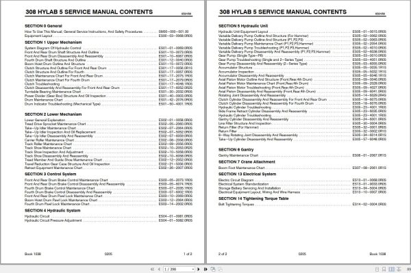
Contents:
SECTION 0 General
How To Use This Manual, General Service Instructions, And Safety Procedures SM00-000-001.00
ES00-03-0068.0R0S : Equipment Layout
SECTION 1 Upper Mechanism
ES01-01-0069.0R0S : System Diagram Of Hydraulic Control
ES01-10-0073.0R0S : Front And Rear Drum Shaft Structure And Outline
ES01-10-6067.0R0S : Front And Rear Drum Disassembly And Reassembly
ES01-12-0040.0R0S : Fourth Drum Shaft Structure And Outline
ES01-15-0072.0R0S : Boom Hoist Drum Outline And Structure
ES01-17-0056.0R1S : Clutch Structure And Outline For Front And Rear Drum
ES01-17-0057.0R0S : Clutch Structure And Outline For Fourth
ES01-17-2075.1R0S : Clutch Maintenance Chart For Front And Rear Drum
ES01-17-2079.0R0S : Clutch Maintenance Chart For Fourth Drum
ES01-17-4048.1R0S : Clutch Troubleshooting
ES01-17-6052.0R2S : Clutch Disassembly And Reassembly For Front And Rear Drum
ES01-30-2032.0R0S : Turntable Bearing Maintenance Chart
ES01-40-0003.0R0S : Power Divider (Gear Box) Structure And Oil Inspection
ES01-42-2076.0R0S : Drum Maintenance Chart
ES01-50-4001.1R0S : Drum Indicator Troubleshooting (Mechanical Type)
SECTION 2 Lower Mechanism
ES02-01-0058.0R0S : Lower General Explanation
ES02-05-2060.0R0S : Tread Drive Sprocket Maintenance Chart
ES02-07-2064.0R0S : Take-Up Idler Maintenance Chart
ES02-07-5052.0R0S : Take-Up Idler Inspection And Oil Replacement
ES02-07-6059.0R0S : Take-Up Idler Disassembly And Reassembly
ES02-08-2058.0R0S : Carrier Roller Maintenance Chart
ES02-09-2056.0R0S : Track Roller Maintenance Chart
ES02-10-2053.0R2S : Track Shoe Maintenance Chart
ES02-10-5058.0R0S : Track Shoe Inspection And Adjustment
ES02-10-6058.0R0S : Track Shoe Disassembly And Reassembly
ES02-12-2052.0R0S : Tread Member And Guide Shoe Maintenance Chart
ES02-21-5056.0R0S : Travel Reduction Gear Case Structure And Oil Inspection
ES02-26-2007.0R0S : Retract Equipment Maintenance Chart
SECTION 3 Control System
ES03-05-2073.1R0S : Front And Rear Drum Brake Control Maintenance Chart
ES03-05-6074.1R0S : Front And Rear Drum Brake Control Disassembly And Reassembly
ES03-07-2035.1R0S : Fourth Drum Brake Control Maintenance Chart
ES03-07-6002.1R0S : Fourth Drum Brake Control Disassembly And Reassembly
ES03-10-2069.0R0S : Front And Rear Drum Pawl Lock Maintenance Chart
ES03-12-2064.0R0S : Boom Hoist Drum Pawl Lock Maintenance Chart
ES03-14-2002.0R0S : Fourth Drum Pawl Lock Maintenance Chart
SECTION 4 Hydraulic System
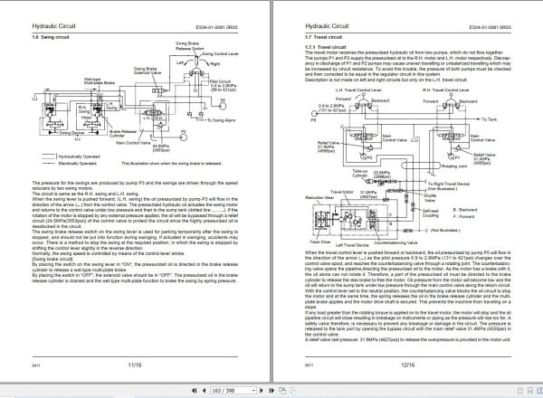
ES04-01-0081.0R0S : Hydraulic Circuit
ES04-01-5082.0R0S : Hydraulic Circuit Pressure Adjustment
SECTION 5 Hydraulic Unit
ES05-01-0015.0R0S : Hydraulic Unit Equipment Layout
ES05-02-0062.0R0S : Variable Delivery Pump Outline And Structure (For Hammer)
ES05-02-0063.0R0S : Variable Delivery Pump Outline And Structure (P1,P2,P3)
ES05-02-2054.0R0S : Variable Delivery Pump Maintenance Chart (P1,P2,P3,Hammer)
ES05-02-4010.0R0S : Variable Delivery Pump Troubleshooting (P1,P2,P3,Hammer)
ES05-02-6038.0R0S : Variable Delivery Pump Disassembly And Reassembly (P1,P2,P3,Hammer)
ES05-03-0010.0R0S : Gear Pump (Single Type-P6)
ES05-03-4051.0R0S : Gear Pump Troubleshooting (Single and 2-Series Type)
ES05-03-6055.0R0S : Gear Pump Disassembly And Reassembly (2-Series Type)
ES05-05-0035.1R1S : Accumulator Structure
ES05-05-5032.1R1S : Accumulator Inspection
ES05-05-6046.1R1S : Accumulator Disassembly And Reassembly
ES05-09-0046.0R0S : Axial Piston Motor Outline And Structure (Front,Rear,4th Drum)
ES05-09-2028.0R0S : Axial Piston Motor Maintenance Chart (Front,Rear,4th Drum)
ES05-09-4027.0R0S : Axial Piston Motor Troubleshooting (Front,Rear,4th Drum)
ES05-09-6041.0R0S : Axial Piston Disassembly And Reassembly (Front,Rear,4th Drum)
ES05-14-6029.2R4S : Rotating Joint Disassembly And Reassembly
ES05-18-6075.0R0S : Clutch Cylinder Disassembly And Reassembly For Front And Rear Drum
ES05-18-6076.0R0S : Clutch Cylinder Disassembly And Reassembly For Fourth Drum
ES05-23-4001.1R0S : Hydraulic Cylinder Troubleshooting
ES05-23-6035.0R0S : Side Frame Retract Cylinder Disassembly And Reassembly
ES05-23-4001.1R0S : Hydraulic Cylinder Troubleshooting
ES05-24-6001.0R0S : Gantry Cylinder Disassembly And Reassembly
ES05-30-0004.0R0S : Line Filter Structure And Inspection
ES05-32-0001.0R0S : Return Filter (For Hammer)
ES05-32-0002.0R1S : Return Filter
ES05-34-6014.0R1S : 8-Way Rotating Joint Disassembly And Reassembly
ES05-57-6048.0R0S : Take-Up Cylinder Disassembly And Reassembly
SECTION 6 Gantry
ES06-01-2067.0R1S : Gantry Maintenance Chart
SECTION 7 Crane Attachment
ES07-08-2061.0R1S : Boom Foot Maintenance Chart
SECTION 13 Electrical System
ES13-01-0068.0R0S : Electric Circuit Diagram
ES13-01-9033.0R0S : Electrical System Standardization
ES13-04-5004.0R0S : Storage Battery Servicing And Installation
ES13-10-0007.0R0S : Electrical Equipment Layout, Wiring And Wire Harness
SECTION 14 Tightening Torque Table
ES14-02-0004.0R0S : Bolt Tightening Torques
Related Products
-
Link Belt Crane YC18-48 Operation Manual 257
10 USDSize: 5.04 MBFormat: PDFLanguage: EnglishBrand: Link BeltType of Machine: CraneType of Manual: Operation ManualModel: Link Belt YC18-48 CraneBook Number: 257Number of Pages: 84 PagesContents:Operating InstructionsProtective Piaintenance And LubricationPeriodic AdjustmentsHydraulic Pressure SettingSpecifications And General Information
REALEASE :
REALEASE :
-
Link Belt Crane 10.3GB PDF [03.2021] All Model Service Manual Full DVD
Original price was: 600.300Current price is: 300. USDLink Belt Crane 10.3GB PDF [03.2021] All Model Service Manual Full DVDSize: 10.3 GBFormat: PDFLanguage: EnglishBrand: Link BeltType Of Machine: CraneType Of Document: Service ManualWindow: all Window 32 and 64 bitAmount of DVD: 1 DVD RARHigh speed link downloadHot-50%
REALEASE :
05.03.2021
REALEASE :
05.03.2021
-
Link Belt Crane UC-78B Operation Manual 518
10 USDSize: 16.07 MBFormat: PDFLanguage: EnglishBrand: Link BeltType of Machine: CraneType of Manual: Operation ManualModel: Link Belt UC-78B CraneBook Number: 518Number of Pages: 158 Pages
REALEASE :
REALEASE :
-
Link Belt Crane UC-98A Operation Manual 198
10 USDSize: 18.07 MBFormat: PDFLanguage: EnglishBrand: Link BeltType of Machine: CraneType of Manual: Operation ManualModel: Link Belt UC-98A CraneBook Number: 198Number of Pages: 186 Pages
REALEASE :
REALEASE :
-
Link Belt Crane 3.53GB PDF 2021 All Model Operator Manual Full DVD
Original price was: 200.115Current price is: 115. USDLink Belt Crane 3.53GB PDF 01.2021 All Model Operator Manual Full DVDSize : 3.53 GB (PDF Files)Format: PDFLanguage: EnglishBrand: Link BeltType of machine: CraneType of document: Operator ManualDate: Full UpdatedMount of the disk: 1 DVDOS: All WindowHigh-Speed Link DownloadHot-43%
REALEASE :
26.01.2021
REALEASE :
26.01.2021
-
Link Belt Crane YC18 YC48 Operation Manual 257
10 USDSize: 5.04 MBFormat: PDFLanguage: EnglishBrand: Link BeltType of Machine: CraneType of Manual: Operation ManualModel: Link Belt YC18 YC48 CraneBook Number: 257Number of Pages: 84 PagesContents:Operating InstructionsProtective Piaintenance And LubricationPeriodic AdjustmentsHydraulic Pressure SettingSpecifications And General Information
REALEASE :
REALEASE :
-
Link Belt Crane 2.09GB PDF [01.2021] All Model Diagram Schematics Full DVD
Original price was: 300.160Current price is: 160. USDLink Belt Crane 2.09GB PDF [01.2021] All Model Diagram Schematics Full DVDSize : 2.09GB (PDF Files)Format: PDFLanguage: EnglishBrand: Link-BeltType of machine: CraneType of document: Diagram SchematicsDate: Full UpdatedMount of the disk: 1 DVDOS: All WindowHigh-Speed Link DownloadHot-47%
REALEASE :
27.01.2021
REALEASE :
27.01.2021
-
Link Belt Crane UC-108 UC-108B Operation Manual 200
10 USDSize: 7.62 MBFormat: PDFLanguage: EnglishBrand: Link BeltType of Machine: CraneType of Manual: Operation ManualModel: Link Belt UC-108 UC-108B CraneBook Number: 200Number of Pages: 76 Pages
REALEASE :
REALEASE :