Description
List of Files:
Link Belt Excavator 130X4 Service Manual WLSM1307-03LX 1.pdf (1641 Pages)
Link Belt Excavator 130X4 Service Manual WLSM1307-03LX 2.pdf (1763 Pages)
Contents:
Link Belt Excavator 130×4 Service Manual Wlsm1307-03lx 1.Pdf (1641 Pages)
Excavator
Safety
Safety, General Information And Standard Torque Data
General Information
Safety
Rops
Rops Judgment
Standard Torque Data For Cap Screws And Nuts
Bolt And Nut Tightening
A. Lower
Main Equipment Table
Lower Component
Travel Unit
Take-Up Roller
Upper Roller
Lower Roller
Recoil Spring
Shoe
Shoe (Lc)
Center Joint
Center Joint (Blade)
Main Equipment Structure And Operation Explanation
Travel Motor
Safety Precautions
Data
Use Of Product
Specifications
Type Indication
Outside Dimension Diagram And Hydraulic Circuit Diagram
Basic Structure And Drawing
Assembly Cross-Section Diagram
Part List
Exploded Views
Operation Explanation
Reduction Gear
Hydraulic Motor Section
Usage Precautions
Installation Instructions
Line
Hydraulic Fluid
Maintenance And Inspection
Daily Inspection
Replacement Of Hydraulic Fluid
Lubricant
Table Of Seals
Failure And Necessary Action
Storage Of Travel Motor
Port Diagram
Travel Motor
Center Joint
Center Joint (Blade)
Basic Functions
Travel Speed Selection
Travel Alarm
Removal And Installation Of Track
Removal And Installation Of Shoe Assembly
Removal Of Shoe Assembly
Installation Of Shoe Assembly
Removal And Installation Of Shoe Plate
Removal Of Shoe Plate
Installation Of Shoe Plate
Removal And Installation Of Roller
Removal And Installation Of Upper Roller
Removal Of Upper Roller
Installation Of Upper Roller
Assembly And Disassembly Of Upper Roller
Configuration Diagram
Dimension Diagram
Jig Dimension Diagram
Disassembly Procedures
Assembly Procedures
Removal And Installation Of Lower Roller
Removal Of Lower Roller
Installation Of Lower Roller
Assembly And Disassembly Of Lower Roller
Configuration Diagram
Dimension Diagram
Jig Dimension Diagram
Disassembly Procedures
Assembly Procedures
Removal And Installation Of Drive Sprocket
Removal Of Drive Sprocket
Installation Of Drive Sprocket
Removal And Installation Of Take-Up Roller
Removal Of Take-Up Roller
Installation Of Take-Up Roller
Assembly And Disassembly Of Take-Up Roller
Configuration Diagram
Dimension Diagram
Jig Dimension Diagram
Disassembly Procedures
Assembly Procedures
Removal And Installation Of Grease Cylinder
Removal Of Grease Cylinder
Installation Of Grease Cylinder
Assembly And Disassembly Of Tension Shock Absorber
Configuration Diagram
Dimension Diagram
Jig Dimension Diagram
Disassembly Procedures
Assembly Procedures
Removal And Installation Of Center Joint
Removal Of Center Joint
Installation Of Center Joint
Assembly And Disassembly Of Center Joint
Configuration Diagram
Dimension Diagram
Dimension Diagram (Blade)
Jig Dimension Diagram
Disassembly Procedures
Assembly Procedures
Removal And Installation Of Travel Motor
Removal Of Travel Motor
Installation Of Travel Motor
Assembly And Disassembly Of Travel Motor
Safety Precautions
Service Overview
Tools
Tightening Torque
Weight Table
Disassembly
Preparations
General Work Precautions
Disassembly Procedure
Maintenance Standards
Seals
Maintenance Standards For Worn Components
Assembly
Preparations
General Work Precautions
Assembly Procedure
Performance Check Test
Maintenance Standards
Drive Sprocket
Take-Up Roller
Upper Roller
Lower Roller
Track Shoe (Grouser Shoe)
Inspection Gauge
For Drive Sprocket
For Take-Up Roller
For Upper Roller
For Lower Roller
Pressure Measurement And Adjustment Procedures
Main Pressure Measurement
B. Travel Pressure Measurement
Drain Volume Measurement Procedures
Preparations
Travel Motor Drain Volume Measurement
Air Bleed Procedure
Travel Motor
B. C. Swing Unit, Counterweight
Main Equipment Table
Upper Component
Swing Unit
Main Equipment Structure And Operation Explanation
Swing Motor
Swing Motor Operation Explanation
Hydraulic Motor Section
Valve Casing Section
Brake Section
Relief Valve Operation Explanation (Relief Valve Model: Krd22ek10)
Swing Motor Internal Structure Diagram
Port Diagram
Swing Motor
Basic Functions
Swing Brake
Swing Lock
Swing Speed Limit
Swing Relief Cut
Removal And Installation Of Swing Unit
Removal Of Swing Unit
Installation Of Swing Unit
Assembly And Disassembly Of Swing Motor
Causes Of Trouble And Solutions
Jig
Disassembly
Assembly
Swing Motor Internal Structure Diagram
Assembly And Disassembly Of Swing Unit
Disassembly
Assembly
Swing Reduction Gear Structure Diagram
Removal And Installation Of Counterweight
Removal Of Counterweight
Installation Of Counterweight
Pressure Measurement And Adjustment Procedures
Main Pressure Measurement
C. Swing Pressure Measurement
Drain Volume Measurement Procedures
Preparations
Swing Motor Drain Volume Measurement
Air Bleed Procedure
Swing Motor
Check
H. Engine
Main Equipment Table
Engine-Related
Engine
Air Cleaner (Double Element)
Radiator
Scr
Basic Functions
Fuel Gauge
Coolant Temperature Gauge
Scr Gauge
Fuel Economy Gauge
Neutral Start
Power-Cut Delay
Preheat
Throttle
Throttle Volume Position Detection
Idling Start
Auto Idle
One-Touch Idle
Auto Warm-Up
Idle Shutdown
Idle Up
Work Mode Control
Engine Emergency Stop
Scr Re-Gen
Inducement
Feed Pump Automatic Stop
Coolant Level Decrease
Air Filter Clogging
Fuel Filter Clogging
Battery Charge Abnormality
Horsepower Reduction Control (In Uplands)
Horsepower Reduction Control (At Engine Failure)
Primary Specifications
Function, Structure, Operation
Function, Structure, Operation (Scr)
Scr Control System Inspection
Operation Explanation Of Scr
Diagnosis For Each Symptom
Intermittent Conditions Of Urea Selective Catalytic Reduction System
Urea Fluid Consumption Too High
Ammonia Smell Noticeable
White Crystalline Powder Visible
Diagnosis For Each Symptom
Engine Start Problem
Engine Stalling
Engine Hunting, Rough Idling
Excessive White Smoke In Exhaust Gas
Excessive Black Smoke In Exhaust Gas
Abnormal Noise
High Fuel Consumption
High Oil Consumption
Engine Output Deficiency
Functional Inspection
Engine Compression Pressure Inspection
Fuel System Inspection
Lubrication System Check
Suction Air System Inspection
Exhaust System Inspection
Egr Control System Inspection
Start System Inspection
Glow Control System Check
Obd System Check
Inspection Of The Monitor Warning Light Illumination Circuit System
Inspection Of The Monitor Warning Light Blinking Circuit System
Inspection Of The Starter Circuit System
Removal And Installation Of Engine Assembly
Removal Of Engine Assembly
Installation Of Engine Assembly
Removal And Installation Of Fuel Cooler, Engine Intercooler, Radiator, And Oil Cooler
Removal And Installation Of Fuel Cooler
Removal Of Fuel Cooler
Installation Of Fuel Cooler
Removal And Installation Of Engine Intercooler
Removal Of Intercooler
Installation Of Inter Cooler
Inspection Of Intercooler
Removal And Installation Of Radiator
Removal Of Radiator
Installation Of Radiator
Inspection Of Radiator
Removal And Installation Of Oil Cooler
Removal Of Oil Cooler
Installation Of Oil Cooler
Removal And Installation Of Turbo Charger
Turbocharger Assembly Removal
Turbocharger Assembly Installation
Inspection Of Turbo Charger
Removal And Installation Of Egr Valve
Removal
Installation
Inspection
Removal And Installation Of Egr Cooler
Removal
Installation
Inspection
Removal And Installation Of Engine Hood
Removal Of Engine Hood
Installation Of Engine Hood
Removal And Installation Of Scr
Removal Of Scr
Installation Of Scr
Removal And Installation Of Scr Catalyst
Removal
Installation
Disassembly
Assembly
Inspection
Removal And Installation Of Cylinder Head Cover
Cylinder Head Cover Removal
Installation Of Cylinder Head Cover
Removal And Installation Of Cylinder Head
Removal Of Cylinder Head
Disassembly Of Cylinder Head
Assembly Of Cylinder Head
Installation Of Cylinder Head
Inspection
Removal And Installation Of Cylinder Block
Removal Of Cylinder Block
Installation Of Cylinder Block
Inspection
Lubrication System
Removal And Installation Of Oil Pan And Crank Case
Removal Of Oil Pan And Crank Case
Installation Of Oil Pan And Crank Case
Removal And Installation Of Oil Level Switch
Removal Of Oil Level Switch
Installation Of Oil Level Switch
Removal And Installation Of Oil Pump Assembly
Removal Of Oil Pump Assembly
Disassembly Of Oil Pump Assembly
Assembly Of Oil Pump Assembly
Installation Of Oil Pump Assembly
Inspection
Engine Oil Inspection
Removal And Installation Of Oil Port Cover
Removal Of Oil Port Cover
Installation Of Oil Port Cover
Cooling System
Removal And Installation Of Water Pump Assembly
Removal Of Water Pump Assembly
Installation Of Water Pump Assembly
Inspection
Removal And Installation Of Thermostat
Removal Of Thermostat
Installation Of Thermostat
Inspection
Inspectioninspection Of Coolant
Inspection Of Cooling Fan Belt
Removal And Installation Of Overheat Switch
Removal Of Overheat Switch
Installation Of Overheat Switch
Induction System
Inspection Of Air Cleaner Element
Exhaust System
Removal And Installation Of Oxidation Catalyst Assembly
Removal
Installation
Aux. Emission Control Devices System
Removal And Installation Of Dosing Module
Removal
Disassembly
Assembly
Installation
Removal And Installation Of Def Supply Module
Removal
Disassembly
Assembly
Installation
Removal And Installation Of Coolant Control Valve
Removal
Installation
Removal And Installation Of Dcu
Removal
Installation
Removal And Installation Of Def Supply Module Filter
Removal
Installation
Appendixes
Removal And Installation Of Exhaust Manifold
Removal Of Exhaust Manifold
Installation Of Exhaust Manifold
Inspection
Removal And Installation Of Fuel Tank
Removal Of Fuel Tank
Installation Of Fuel Tank
Removal And Installation Of Urea Pump
Removal Of Urea Pump
Installation Of Urea Pump
Removal And Installation Of Urea Solution Tank
Removal Of Urea Solution Tank
Installation Of Urea Solution Tank
Removal And Installation Of Fuel Supply Pump
Removal Of Fuel Supply Pump
Installation Of Fuel Supply Pump
Removal And Installation Of Common Rail Assembly
Removal Of Common Rail Assembly
Installation Of Common Rail Assembly
Removal And Installation Of Injector
Removal Of Injector
Installation Of Injector
Removal And Installation Of Starter Motor
Removal Of Starter Motor
Installation Of Starter Motor
Disassembly Of Starter Motor
Assembly Of Starter Motor
Inspection Of Starter Motor
Removal And Installation Of Alternator
Removal Of Alternator
Installation Of Alternator
Removal And Installation Of Glow Plug
Removal Of Glow Plug
Installation Of Glow Plug
Inspection
Removal And Installation Of Suction Control Valve
Removal Of Suction Control Valve
Installation Of Suction Control Valve
Removal And Installation Of Fuel Filter
Removal Of Fuel Filter
Installation Of Fuel Filter
Removal And Installation Of Fuel Filter Pressure
Fuel Filter Pressure Sensor Removal
Fuel Filter Pressure Sensor Installation
Removal And Installation Of Engine Coolant Temperature Sensor
Engine Coolant Temperature Sensor Removal
Engine Coolant Temperature Sensor Installation
Inspection
Removal And Installation Of Ckp Sensor
Ckp Sensor Removal
Ckp Sensor Installation
Inspection
Removal And Installation Of Cmp Sensor
Cmp Sensor Removal
Cmp Sensor Installation
Inspection
Removal And Installation Of Oil Pressure Sensor
Oil Pressure Sensor Removal
Oil Pressure Sensor Installation
Inspection
Removal And Installation Of Pressure Sensor/Boost Temperature Sensor
Removal Of Pressure Sensor/Boost Temperature Sensor
Installation Of Pressure Sensor/Boost Temperature Sensor
Inspection Of Pressure Sensor/Boost Temperature Sensor
Removal And Installation Of Imt Sensor
Imt Sensor Removal
Imt Sensor Installation
Removal And Installation Of Charge Air Cooler Temperature Sensor 1
Removal Of Charge Air Cooler Temperature Sensor 1
Installation Of Charge Air Cooler Temperature Sensor 1
Inspection Of Charge Air Cooler Temperature Sensor 1
Sampling Procedure
Sampling Of Engine Oil
Removal And Installation Of Exhaust Gas Temperature Sensor
Removal
Installation
Inspection
Removal And Installation Of Egr Gas Temperature Sensor 1
Removal
Installation
Inspection
Removal And Installation Of Egr Gas Temperature Sensor 2
Removal
Installation
Inspection
Removal And Installation Of Nox Sensor
Removal
Installation
Removal And Installation Of Egr Gas Temperature Sensor 3
Removal
Installation
Removal And Installation Of Def Sensor
Removal
Installation
Engine-Related Diagnostic Trouble Code List
Engine-Side Trouble
Ecm Trouble
Dtc U0001 Can Bus Error (Iso-Can)
Dtc P0016 Crankshaft Position – Camshaft Position Correlation Error
Dtc P0045 Turbocharger Boost Control Vnt Error
Dtc U0073 Control Module Communication Bus Off
Dtc P0087 Fuel Rail/System Pressure – Too Low
Dtc P0089 Fuel Pressure Regulator Performance
Dtc P0091 Fuel Pressure Regulator Control Circuit Low
Dtc P0092 Fuel Pressure Regulator Control Circuit High
Dtc P0097 Intake Air Temperature (Iat) Sensor 2 Circuit Low Voltage
Dtc P0098 Intake Air Temperature (Iat) Sensor 2 Circuit High Voltage
Dtc U0101 Lost Communication With Can
Dtc P0102 Mass Air Flow Sensor Circuit Low Input
Dtc P0103 Mass Air Flow Sensor Circuit High Input
Dtc U010e Lost Communications With Dosing Control Module
Dtc U0110 Lost Communication With Vnt System
Dtc P0112 Intake Air Temperature Sensor Circuit Low
Dtc P0113 Intake Air Temperature Sensor Circuit High
Dtc P0117 Engine Coolant Temperature Sensor Circuit Low
Dtc P0118 Engine Coolant Temperature Sensor Circuit High
Dtc P0122 Throttle Position Sensor Circuit Low
Dtc P0123 Throttle Position Sensor Circuit High
Dtc P0182 Fuel Temperature Sensor Circuit Low
Dtc P0183 Fuel Temperature Sensor Circuit High
Dtc P0192 Fuel Rail Pressure Sensor Circuit Low
Dtc P0193 Fuel Rail Pressure Sensor Circuit High
Dtc P0201 Injector Circuit Open – Cylinder 1
Dtc P0202 Injector Circuit Open – Cylinder 2
Dtc P0203 Injector Circuit Open – Cylinder 3
Dtc P0204 Injector Circuit Open – Cylinder 4
Dtc P0217 Engine Coolant Over Temperature Condition
Dtc P0219 Engine Overspeed Condition
Dtc P0234 Turbocharger Overboost Condition
Dtc P0237 Turbo Charger Boost Sensor Circuit Low
Dtc P0238 Turbo Charger Boost Sensor Circuit High
Dtc P0335 Crankshaft Position Sensor Circuit
Dtc P0336 Crankshaft Position Sensor Circuit Range/Performance
Dtc P0340 Camshaft Position Sensor Circuit
Dtc P0380 Glow Relay Circuit Error
Dtc P0401 Egr Flow Insufficient Detected
Dtc P0404 Egr Control Circuit Range/Performance
Dtc P0409 Egr Sensor Circuit
Dtc U0411 Lost Can Communications With Vnt Control Module
Dtc P041c Egr Cooler Outlet 1 Temp Sensor Circuit Low
Dtc P041d Egr Cooler Outlet 1 Temp Sensor Circuit High
Dtc P0427 Catalyst Temperature Sensor Circuit Low Sensor 1
Dtc P0428 Catalyst Temperature Sensor Circuit High Sensor 1
Dtc P042c Catalyst Temperature Sensor Circuit Low Sensor 2
Dtc P042d Catalyst Temperature Sensor Circuit High Sensor 2
Dtc P0522 Engine Oil Pressure Sensor Circuit Low Input
Dtc P0523 Engine Oil Pressure Sensor Circuit High Input
Dtc P0545 Egr Cooler Inlet 1 Temp Sensor Circuit Low
Dtc P0546 Egr Cooler Inlet 1temp Sensor Circuit High
Dtc P0560 12 Volt Circuit Error
Dtc P0563 System Voltage High
Dtc P0601 Internal Control Module Memory Check Sum Error
Dtc P0602 Internal Control Module Qr Code Error
Dtc P0604 Internal Control Module Ram Error
Dtc P0606 Internal Control Module Cpu Error
Dtc P060a Internal Control Module Cpu Ic Error
Dtc P060c Internal Control Module A/D Processing Performance
Dtc P0615 Starter Relay Circuit Error
Dtc P0638 Throttle Actuator Control Range/Performance
Dtc P0685 Ecm Power Relay Control Circuit Open
Dtc P0687 Ecm Power Relay Control Circuit High
Dtc P06a6 Sensor Reference Voltage 1 Circuit
Dtc P06a7 Sensor Reference Voltage 2 Circuit
Dtc P06a8 Sensor Reference Voltage 3 Circuit
Dtc P06a9 Sensor Reference Voltage 4 Circuit
Dtc P06af Torque Management System – Forced Engine Shutdown
Dtc P06d5 Sensor Reference Voltage 5 Circuit
Dtc P1076 Charge Air Cooler (Cac) Temperature Sensor 1 Circuit Low Voltage
Dtc P1077 Charge Air Cooler (Cac) Temperature Sensor 1 Circuit High Voltage
Dtc P1093 Fuel Rail Pressure Too Low
Dtc P1097 Compressor Outlet Temperature Sensor Circuit High
Dtc P1098 Compressor Outlet Temperature Sensor Circuit High
Dtc P1236 Charge Air Cooler Performance Failure
Dtc P1261 Injector Positive Voltage Control Circuit Group 1
Dtc P1262 Injector Positive Voltage Control Circuit Group 2
Dtc P1404 Egr Position Fault
Dtc P1606 Sw-Ic Internal Failure
Dtc P160b Ad-Ic Failure Error
Dtc P160c Ad-Ic2 Failure Error
Dtc P1621 Control Module Long Term Memory Performance
Dtc P1669 Dpd Lamp Control Circuit
Dtc P204f Scr System Error (No Inducement)
Dtc P207f Urea Fluid Concentration Too Low
Dtc P20c9 Scr System Error
Dtc U2106 Lost Can Communications With Wheel Loader Transmission Control System
Dtc P2122 Pedal Position Sensor 1 Circuit Low Input
Dtc P2123 Pedal Position Sensor 1 Circuit High Input
Dtc P2127 Pedal Position Sensor 2 Circuit Low Input
Dtc P2128 Pedal Position Sensor 2 Circuit High Input
Dtc P2138 Pedal Position Sensor 1 – 2 Voltage Correlation
Dtc P2146 Fuel Injector Group 1 Supply Voltage Circuit
Dtc P2149 Fuel Injector Group 2 Supply Voltage Circuit
Dtc P2228 Barometric Pressure Sensor Circuit Low
Dtc P2229 Barometric Pressure Sensor Circuit High
Dtc P2457 Exhaust Gas Recirculation (Egr) Cooling System Performance
Dtc P2458 Purge Time Out Error
Dtc P2ba7 Urea Fluid Quantity Too Low
Dtc P2baa Scr System Error (Inducement, No Purge)
Dtc P3093 Fuel Rail Pressure Too Low
Dcu Trouble
Dtc U0002 Can Bus Off
Dtc U0100 Lost Communication With Ecm
Dtc U029d Lost Communication With Nox Sensor 1
Dtc P0607 Control Module Performance
Dtc P060b Internal Control Module A/D Processing Performance
Dtc P062f Control Module Eeprom Error
Dtc P0641 Sensor Reference Voltage 1 Circuit
Dtc P0658 Actuator Supply Voltage Circuit
Dtc P0659 Actuator Supply Voltage Circuit
Dtc P1462 Urea Fluid Quality Sensor Timeout Error
Dtc P1464 Main Relay Performance
Dtc P1468 Dcu Overtemperature
Dtc P1491 Urea Fluid Overpressure
Dtc P1493 Dcu Driver Overtemperature
Dtc P149c Urea Fluid Pressure Reduction Malfunction
Dtc P149d Urea Fluid Tank Overtemperature
Dtc P203b Urea Fluid Tank Level Sensor Stuck
Dtc P203c Urea Fluid Tank Level Sensor Low Voltage
Dtc P203d Urea Fluid Tank Level Sensor High Voltage
Dtc P2048 Urea Fluid Injector Circuit Low Voltage
Dtc P2049 Urea Fluid Injector Circuit High Voltage
Dtc P204b Urea Fluid Pressure Sensor Performance
Dtc P204c Urea Fluid Pressure Sensor Circuit Low Voltage
Dtc P204d Urea Fluid Pressure Sensor Circuit High Voltage
Dtc P205b Urea Fluid Tank Temperature Sensor Performance
Dtc P205c Urea Fluid Tank Temperature Sensor Low Voltage
Dtc P205d Urea Fluid Tank Temperature Sensor High Voltage
Dtc P206a Urea Fluid Quality Sensor Circuit
Dtc P206b Urea Sensor Over Temperature Condition
Dtc P206c Urea Fluid Quality Sensor Circuit Low Voltage
Dtc P206d Urea Fluid Quality Sensor Circuit High Voltage
Dtc P207f Urea Fluid Concentration Too Low
Dtc P208a Urea Fluid Pump Control Circuit
Dtc P208b Usea Fluid Pump Performance
Dtc P208c Urea Fluid Pump Control Circuit Low Voltage
Dtc P208d Urea Fluid Pump Control Circuit High Voltage
Dtc P208e Urea Fluid Injector Stuck
Dtc P20a0 Urea Fluid Reverting Valve Circuit Open
Dtc P20a2 Urea Fluid Reverting Valve Circuit Low Voltage
Dtc P20a3 Urea Fluid Reverting Valve Circuit High Voltage
Dtc P20ac Urea Fluid Pump Temperature Sensor Performance
Dtc P20ad Urea Fluid Pump Module Temperature Sensor Performance
Dtc P20b1 Urea Fluid Tank Heater Coolant Control Valve Circuit Open
Dtc P20b3 Urea Fluid Tank Heater Coolant Control Valve Circuit Low Voltage
Dtc P20b4 Urea Fluid Tank Heater Coolant Control Valve Circuit High Voltage
Dtc P20e8 Urea Fluid Pressure Underpressure
Dtc P20e9 Urea Fluid Overpressure
Dtc P20ea Urea Fluid Pressure Reduction Malfunction
Dtc P20fe Urea Fluid Pressure Build-Up Error
Dtc P2201 Upstream Nox Sensor Performance
Dtc P2206 Nox Sensor Heater Control Circuit Low Voltage Sensor 1
Dtc P2207 Nox Sensor Heater Control Circuit High Voltage Sensor 1
Dtc P242b Exhaust Gas Temperature (Egt) Sensor 3 Performance
Dtc P242c Exhaust Gas Temperature (Egt) Sensor 3 Circuit Low Voltage
Dtc P242d Exhaust Gas Temperature (Egt) Sensor 3 Circuit High Voltage
Data Reference Values
Idle Speed
Two Pump Relief
J. Hydraulic Equipment (Pump, Operation System Valve)
Main Equipment Table
Hydraulic Device
Hydraulic Pump (Standard)
Hydraulic Pump (Blade)
Control-Related
Control Valve (Standard)
Control Valve (Blade)
Solenoid Valve (4 Stack)
Remote Control Valve For Left/Right Operations
Remote Control Valve For Travel Operation
Valve For Blade Operation
Remote Control Valve Characteristic Diagram
Operation Remote Control Valve Control Diagram
Travel Remote Control Valve Control Diagram
Blade Remote Control Valve Control Diagram
Cushion Valve (Heat Circuit, With Shuttle Valve)
Selector Valve
Relief Valve (Electromagnetic Proportional)
Basic Functions
Oil Temperature Gauge
Static Horsepower Control
Overload Warning (Function For Europe Only)
Pressure Boost Control
Stroke Control
Boom Down Energy Save
Pump Horsepower Boost Control
Arm 1 Semi-Parallel Control
Arm 2 Semi-Parallel Control
Hot Shutdown Warning
Gate Lock
Breaker Mode
Crusher Mode
Quick Coupler
Hydraulic Filter Clogging
Solenoid Sticking Prevention
Port Diagram
Hydraulic Pump (Standard Model)
Hydraulic Pump (Blade)
Control Valve
Relief Valve
Relief Valve (Blade)
4 Stack Solenoid Valve
2 Stack Solenoid Valve
Remote Control Valves (Upper, Travel)
Remote Control Valves (Left-Right)
Remote Control Valve (Travel)
Remote Control Valve (Blade)
Cushion Valve
2-Way Selector Valve
Direction Valve
Reducing Valve (3 Stack)
Relief Valve (Electromagnetic Proportional)
Manifold Under Cab
Manifold (Accumulator Section)
Hydraulic Oil Tank
Hydraulic Pump
Type Indication
Specifications
Structure And Operation Explanation
Hydraulic Circuit Diagram
Hydraulic Pump Internal Structure Diagram
Overall View
Drive Shaft Front Side
Drive Shaft Rear Side
Development Diagram
Part Table
Regulator
Regulator Operation Explanation
Regulator Operation Explanation Diagram
Internal Configuration Diagram Of Regulator
Development Diagram Of Regulator
Component Table
Operation Outline Of Electronically-Controlled Pump
Control Valve
Basic Configuration
Operation
4 Stack Solenoid Valve Operation Explanation
External Shape Diagram And Component Parts
Operation Explanation
Upper Pilot Valve (Remote Control Valve)
Structure
Function
Operation
Structural Diagram
Travel Pilot Valve (Remote Control Valve)
Operation
Pressure Reducing Valve Section
Damping Mechanism In Operation Section
Structural Diagram
Cushion Valve
Structure
Operation Explanation
Selector Valve (2-Way)
Structure
Operation Explanation
Development Diagram
Direction Valve (3-Direction)
Structure
Operation Explanation
Electromagnetic Relief Valve
Structure
Operation Explanation
Operation Of Check Valve
Operation Of Electromagnetic Relief Valve
Removal And Installation Of Hydraulic Reservoir
Removal Of Hydraulic Reservoir
Installation Of Hydraulic Tank
Removal And Installation Of Hydraulic Pump
Removal Of Hydraulic Pump
Installation Of Hydraulic Pump
Removal And Installation Of Control Valve
Removal Of Control Valve
Installation Of Control Valve
Removal And Installation Of Travel Remote Control Valve
Removal Of Travel Remote Control Valve
Installation Of Travel Remote Control Valve
Removal And Installation Of Operation Remote Control Valve
Removal Of Operation Remote Control Valve (Left)
Installation Of Operation Remote Control Valve (Left)
Removal Of Operation Remote Control Valve (Right)
Installation Of Operation Remote Control Valve (Right)
Removal And Installation Of 4 Stack Solenoid
Removal Of 4 Stack Solenoid
Installation Of 4 Stack Solenoid Valve
Removal And Installation Of Cushion Valve
Removal Of Cushion Valve
Installation Of Cushion Valve
Procedures For Assembly And Disassembly Of Hydraulic Pump Main Unit
Tools
Disassembly Procedure
Assembly Procedure
Pump Main Unit Maintenance Standards
Replacement Standards For Worn Parts
Standards For Repairing Cylinders, Valve Plates, And Swash Plates (Shoe Plates)
Tightening Torque
Overall View
Drive Shaft Front Side
Drive Shaft Rear Side
Development Diagram
Part Table
Causes Of Failures, And Actions
Regulator Adjustment
Appendix Table And Drawings
Regulator Assembly And Disassembly Procedures
Tools
Preparations For Disassembly
Disassembly Procedure
Assembly Procedures
Internal Configuration Diagram Of Regulator
Development Diagram Of Regulator
Component Table
Procedures For Assembly And Disassembly Of Control Valve
Main Plunger Section
Foot Relief Valve
Main Relief Valve
Disassembly
Assembly And Pressure Setting
Pressure Setting
Overload Relief Valve
Center Bypass Valve
Arm Regeneration Check
Boom Back Pressure Check
Load Hold Valve
Boom Regeneration Check
Check Valve
Swing Priority Valve
Check Valve (Swing Priority Path)
Arm Regeneration Valve
Travel Signal Switchover Spool
Procedures For Assembly And Disassembly Of Operation Remote Control Valve
Maintenance Procedures
Required Tools And Tightening Torque
Maintenance Standards
Disassembly Procedures
Assembly Procedures
Causes Of Trouble And Countermeasures
Procedures For Assembly And Disassembly Of Travel Remote Control Valve
Maintenance Procedures
Disassembly Procedures
Assembly Procedures
Causes Of Trouble And Countermeasures And Cross-Section Diagram
Assembly And Disassembly Of Cushion Valve
Disassembly Procedures
Reverse Operation Spool Section
Check Plunger Section With Throttle
Shuttle Valve Section
Assembly Procedures
Reverse Operation Spool Section
Check Plunger Section With Throttle
Shuttle Valve Section
Written Materials
Pressure Measurement And Adjustment Procedures
Procedures For Pressure Measurement From The Monitor Display
Monitor And Switch Panel
Pressure Measurement Method
Operating Method
Procedures For Measuring Hydraulic Oil Temperature From The Monitor Display
Hydraulic Oil Temperature Measurement Method
Operating Method
Procedures For Pressure Measurement By Installing Pressure Gauge
Preparations
Items To Prepare
Pressure Measuring Port
Control Valve
Location Of Relief Valves
Pressure Measurement Preparations
Pressure Measurement
Main Pressure Measurement
A. Attachment Pressure Measurement
Boom-Down Pressure Measurement
D. Option Line Pressure Measurement
Pilot Pressure Measurement
Pressure Gauge Installation
Negative Control Pressure Measurement
Pressure Gauge Installation
Pressure Adjustment
Main Pressure Adjustment
Pressure Measurement And Adjustment Preparations
Main Relief Pressure Adjustment
Overload Relief Pressure Adjustment
Adjustment Of Swing Relief Pressure
Pilot Pressure Adjustment
Hydraulic Pump Flow Measurement Procedures
Preparations
Items To Prepare
Work Preparations
Flow Measurement
Air Bleed Procedure
Hydraulic Pump
Sampling Procedure
Sampling Of Hydraulic Fluid
Hydraulic Equipment Layout
Overall View
Pump Chamber Hydraulic Equipment Layout
Swing Body Center Section Hydraulic Equipment Layout
Housing Left Side Hydraulic Equipment Layout
Layout Of Hydraulic Equipment In Cab
N. Cab
Removal And Installation Of Operator’s Seat
Removal Of Operator’s Seat
Installation Of Operator’s Seat
Removal And Installation Of Cab Assembly
Removal Of Cab Assembly
Installation Of Cab Assembly
Removal And Installation Of Wiper
Removal Of Wiper
Installation Of Wiper
Removal And Installation Of Cab Front Glass
Removal Of Cab Front Glass
Installation Of Cab Front Glass
Window Lock Adjustment Procedures
Window Lock (Front Side)
Window Lock (Rear Side)
Removal And Installation Of Housing Guardrail
Removal Of Housing Guardrail
Installation Of Housing Guardrail
Tightening Torque
R. Electrical Parts
Basic Functions
Monitor Control
Monitor Display Dimming
Diagnostic Trouble Code Indicator
Clock
Basic Operation
Battery Save
Accessories
Working Light
Led Light
Room Lamp
Radio Mute
Wiper And Washer
Safety
Horn
Back/Side View Monitor
Precautions For Camera Installation
Maintenance
Anti-Theft
Manual Lock
Service Support Screen Lock
Customer-Specific System Information Screen Lock
Maintenance Information Screen Lock
Option Line Setting Screen Lock
Setting
Clock Adjustment
Screen Brightness Setting
Battery Disconnect Switch
Explanation Of Controller
Service Support
Screen Operations
Screen Display List
Service Monitor Structure
Check Screen List
Machine Status
Hydraulic Status
Engine Status
Fault History
Work History
Hydraulic History
Engine History
Device Test
Ecm/Dcu Memory Clear
Scr Re-Gen
Urea Line Leak Test
Ccv Operation Test
Dosing Test
Reverting Valve Operation Test
Common Rail Pressure Test
Idle Speed Test / Injector Test
Egr Valve Control Test
Vg Turbo Control Test
Intake Throttle Control Test
Control Unit Screen List
Mcm-Main
Mcm-Sub
Commu. Terminal
Setup Screen List
Machine Select
Dimensions
Parameters
Engine Information
Engine Information
Data Confirmation
Data Transfer (Copy)
Qr (Injector) Code
Injector Number
Screen Layout
Data Source Selection
Manual Input
Camera
Password
Calibrate Screen List
Throttle Volume
Opt.Line Relief
Pump Flow
Reset Screen List
Connection Connector Pin Layout
Main Controller
Monitor
Sequence Circuit Diagram
Code List
Overall
Block Diagram
Main Controller
Dcu
Ecm
Monitor
Air Conditioner
Gate Lock
Horn
Working Light
Option
Other
Electrical Symbol List
Electrical Equipment Layout Diagram
Main Unit Left-Side Layout Diagram
Engine Section Layout Diagram
Main Unit Right Side Layout Diagram (Pump Chamber)
Main Unit Center Section Layout Diagram
Cab Layout Diagram 1
Cab Layout Diagram 2
Layout Around Operator Seat
Stand Alone Parts Diagram
Removal And Installation Of Wiper Controller
Removal Of Wiper Controller
Installation Of Wiper Controller
Removal And Installation Of Wiper Motor
Removal Of Wiper Motor
Installation Of Wiper Motor
Removal And Installation Of Ecm
Removal Of Ecm
Installation Of Ecm
Removal And Installation Of Main Controller
Removal Of Main Controller
Installation Of Main Controller
Removal And Installation Of Dcu
Removal Of Dcu
Installation Of Dcu
Removal And Installation Of Monitor
Removal Of Monitor
Installation Of Monitor
Removal And Installation Of Rear View Camera
Removal Of Rear View Camera
Installation Of Rear View Camera
Removal And Installation Of Side Camera (Right)
Removal Of Side Camera (Right)
Installation Of Side Camera (Right)
Removal And Installation Of Side Camera (Left)
Removal Of Side Camera (Left)
Installation Of Side Camera (Left)
Removal And Installation Of Fvm Controller
Removal Of Fvm Controller
Installation Of Fvm Controller
How To Set Fvm
Air Conditioner Overall Diagram
Frame
Cab
Equipment Layout Diagram
Circuit Diagram
Air Conditioner Circuit Diagram
Explanation Of Functions
Explanation Of Control
Air Mix Motor Actuator Control
Blow Mode Motor Actuator Control
Refresh/Recirculate Switch Motor Actuator Control
Blower Amp Control
Compressor Clutch Control
Coolmax Control And Hotmax Control
Abnormality Detection And Control After Abnormality Detected
Monitor Mode
Door Switch Control
Actuator Inspection
Air Mix Motor Actuator Inspection
Refresh/Recirculate Switch Motor Actuator Inspection
Mode Motor Actuator Inspection
Self-Diagnosis Function With Panel Display
Abnormality Display And Self-Check Procedures
Abnormality Display Position
Explanation Of Abnormality Display
Motor Actuator Abnormality
Sensor Abnormality
Explanation Of Monitor Mode
Monitor Mode Display Position
Monitor Mode Display Operating Method
Display Contents In Monitor Mode
Part Function And Good/Poor Judgment
Control Panel
Blower Amp
Relay
Air Mix Actuator
Refresh/Recirculate Actuator
Blow Mode Actuator
Evaporator Sensor
Dual Pressure Switch
Solar Radiation Sensor
Inside Air Sensor
Assembly And Disassembly Of Unit
Removal Of Blower Unit
Replacement Of Blower Motor
Replacement Of Blower Amp
Removal Of Heater Core
Removal Of Heat Case Right/Left
Replacement Of Evaporator And Expansion Valve
Installation Of Evaporator Sensor
Replacement Of Motor Actuator
Removal And Installation Of Compressor
Removal Of Compressor
Installation Of Compressor
Removal And Installation Of Condenser
Removal Of Condenser
Installation Of Condenser
Removal And Installation Of Receiver Dryer
Removal Of Receiver Dryer
Installation Of Receiver Dryer
Work Precautions
Work Procedures
Air Conditioner Refrigerant Filling Is Divided Into The “Vacuum Operation” And “Gas Filling Operation”.
Operation Chart
Tools
Filling Procedures
Charging Hose Connection Position
Connecting Gauge Manifold
Vacuuming
Gas Filling Operation, High-Pressure Side
Gas Filling Work, Low Pressure Side
V. Attachments
Main Equipment Table
Backhoe Attachment
Cylinder
Cylinder (Blade)
Maintenance Standards
Attachment (Backhoe)
- Boom And Swing Frame Installation Section
- Boom Cylinder And Swing Frame Installation Section
- Boom And Boom Cylinder Installation Section
- Boom And Arm Cylinder Installation Section
- Boom And Arm Installation Section
- Arm And Arm Cylinder Installation Section
- Arm And Bucket Cylinder Installation Section
- Arm And Arm Link Installation Section
- Bucket And Bucket Link Installation Section
- Bucket Link And Bucket Cylinder Installation Section
- Bucket And Arm Installation Section
Dozer Blade - Blade And Blade Cylinder Installation Section
- Lower Frame And Blade Cylinder Installation Section
- Lower Frame And Blade Installation Section
Removal And Installation Of Bucket Cylinder
Removal Of Bucket Cylinder
Installation Of Bucket Cylinder
Removal And Installation Of Arm Cylinder
Removal Of Arm Cylinder
Installation Of Arm Cylinder
Removal And Installation Of Boom Cylinder
Removal Of Boom Cylinder
Installation Of Boom Cylinder
Removal And Installation Of Blade Cylinder
Removal Of Blade Cylinder
Installation Of Blade Cylinder
Procedures For Operation/Assembly And Disassembly Of Hydraulic Cylinder
Specifications And Structure Diagram (Including The Assembly Diagram And Parts Table)
Basic Functions
Function Of Each Location
Cylinder Head Assembly (Made By Kyb)
Piston Assembly (Made By Kyb)
Pipe Assembly (Made By Kyb)
Handling Precautions
Precautions For Installing The Cylinder On The Machine Body
Usage Cautions
Maintenance And Inspection Cautions
Maintenance Inspection And Service
Trouble Diagnostics
Storage Standards
Storing Parts Individually (In Principle, Store Indoors.)
When Mounted On Vehicle Body
Recommended Anti-Rust Oil
Assembly And Disassembly Procedures
Preparations ····· Prepare The Following Before Starting Disassembly.
General Work Precautions
Maintenance Standards
Inspection After Assembly
Required Tool
General Tool
Special Jig (Made By Kyb)
Special Jig Parts Number List (Made By Kyb)
Disassembly Procedures (Made By Kyb)
Assembly Procedures (Made By Kyb)
Test Operation
Usage Limits
Structural Diagram (Made By Kyb)
Boom Cylinder
Arm Cylinder
Bucket Cylinder
Blade Cylinder
Hbcv
Structure
Function
Operation Explanation
Port Diagram
Hbcv
Air Bleed Procedure
Hbcv
Boom Cylinder Hbcv
Arm Cylinder Hbcv
Removal And Installation Of Hbcv
Removal And Installation Of Arm Hbcv
Removal Of Arm Hbcv
Installation Of Arm Hbcv
Removal And Installation Of Boom Hbcv
Removal Of Boom Hbcv
Installation Of Boom Hbcv
Removal And Installation Of Bucket
Removal Of Bucket
Installation Of Bucket
Removal And Installation Of Bucket Link
Removal Of Bucket Link
Installation Of Bucket Link
Removal And Installation Of Arm
Removal Of Arm
Installation Of Arm
Removal And Installation Of Boom
Removal Of Boom
Installation Of Boom
Removal And Installation Of Blade
Removal Of Blade
Blade Installation
Z. Other
Changes From Model -6
Overall Layout
Lower
Swing Unit
Engine
Hydraulic-Related Data
Hydraulic Control
Cab, House
Electrical Data
Electric Control
Attachments
Specifications (Standard)
Engine
Hydraulic System
Hydraulic Controls
Electrical System
Operator Environment
Undercarriage
Mass
Digging Force (With 0.5 M3 Sumitomo Bucket) (Iso 6015)
Dimensions
Working Ranges
System Fluid Capacities And Specifications
Specifications (Blade Specifications)
Engine
Hydraulic System
Hydraulic Controls
Electrical System
Operator Environment
Undercarriage
Dozer Blade
Mass
Digging Force (With 0.5 M3 Sumitomo Bucket) (Iso 6015)
Dimensions
Working Ranges
System Fluid Capacities And Specifications
Specifications (Lc Specifications)
Engine
Hydraulic System
Hydraulic Controls
Electrical System
Operator Environment
Undercarriage
Mass
Digging Force (With 0.5 M3 Sumitomo Bucket) (Iso 6015)
Dimensions
Working Ranges
System Fluid Capacities And Specifications
Arm Dimensions
Main Unit Weight
Divided Weight (Standard Specifications)
Divided Weight (Blade Specifications)
Divided Weight (Lc Specifications)
Stand Alone Part Weight (Standard Specifications)
Stand Alone Part Weight (Blade Specifications)
Shoe Weight (Per Side)
Arm Weight
Bucket Weight
Bolt Size And Torque Table
Special Torque Setting
Overall View
130×4 (Standard Specifications)
Standard Arm [2.50 M (8.2021 Ft.)]
Long Arm [3.01 M (9.8753 Ft.)]
Short Arm [2.11 M (6.9226 Ft.)]
130×4 (Blade Specifications)
Standard Arm [2.50 M (8.2021 Ft.)]
Long Arm [3.01 M (9.8753 Ft.)]
Short Arm [2.11 M (6.9226 Ft.)]
130×4 (Lc Specifications)
Standard Arm [2.50 M (8.2021 Ft.)]
Long Arm [3.01 M (9.8753 Ft.)]
Short Arm [2.11 M (6.9226 Ft.)]
Work Range Diagram
130×4 (Standard Specifications)
Standard Arm [2.50 M (8.2021 Ft.)]
Long Arm [3.01 M (9.8753 Ft.)]
Short Arm [2.11 M (6.9226 Ft.)]
130×4 (Blade Specifications)
Standard Arm [2.50 M (8.2021 Ft.)]
Long Arm [3.01 M (9.8753 Ft.)]
Short Arm [2.11 M (6.9226 Ft.)]
130×4 (Lc Specifications)
Standard Arm [2.50 M (8.2021 Ft.)]
Long Arm [3.01 M (9.8753 Ft.)]
Short Arm [2.11 M (6.9226 Ft.)]
New Machine Performance Judgment Table
Table Of Standards
Measurement Method
Engine Speed
Pressure At Each Part
Pump Command Displacement
Cylinder Down Amount
Attachment Speed
Swing Speed
Swing (180°) Brake Angle
Travel Speed
Off Travel Amount
Travel Sprocket Speed
Shoe Tension Amount
Swing Ball Race Bearing Movement Amount And Bucket Tip Movement Amount
Fluids And Lubricants
Hydraulic Fluid
Engine Oil
Fuel
Conditions Applicable To Diesel Fuel
Recommended Conditions Applicable To Diesel Fuel
Main-Unit-Related Diagnostic Trouble Code List
Main Unit-Side Trouble
Diagnostic Trouble Code: 7000 Pressure Sensor P1 Abnormality
Diagnostic Trouble Code: 7001 Pressure Sensor P2 Abnormality
Diagnostic Trouble Code: 7002 Pressure Sensor N1 Abnormality
Diagnostic Trouble Code: 7003 Pressure Sensor N2 Abnormality
Diagnostic Trouble Code: 7004 Pressure Sensor Boom Cylinder Bottom Abnormality
Diagnostic Trouble Code: 7007 Pressure Sensor Arm Cylinder Rod Abnormality
Diagnostic Trouble Code: 7021 Pressure Sensor Swing Pilot Abnormality
Diagnostic Trouble Code: 7023 Pressure Sensor Arm-In Pilot Abnormality
Diagnostic Trouble Code: 7040 Level Sensor Fuel Abnormality
Diagnostic Trouble Code: 7041 Temperature Sensor Hydraulic Fluid Abnormality
Diagnostic Trouble Code: 7065 Pressure Sensor Boom-Up Pilot Abnormality
Diagnostic Trouble Code: 7067 Pressure Sensor Bucket-Close Pilot Abnormality
Diagnostic Trouble Code: 7068 Pressure Sensor Boom-Down Pilot Abnormality
Diagnostic Trouble Code: 7069 Pressure Sensor Arm-Out Pilot Abnormality
Diagnostic Trouble Code: 7070 Pressure Sensor Bucket-Open Pilot Abnormality
Diagnostic Trouble Code: 7071 Pressure Sensor Travel Right Pilot Abnormality
Diagnostic Trouble Code: 7072 Pressure Sensor Travel Left Pilot Abnormality
Diagnostic Trouble Code: 7073 Pressure Sensor Travel 1 Pedal Abnormality
Diagnostic Trouble Code: 7074 Pressure Sensor 1st Option Pilot (Common/Front Pedal) Abnormality
Diagnostic Trouble Code: 7075 Pressure Sensor Arm Cylinder Bottom Abnormality
Diagnostic Trouble Code: 7078 Pressure Sensor 1st Option Pilot (Rear Pedal) Abnormality
Diagnostic Trouble Code: 7200 Swing Brake Solenoid Abnormality
Diagnostic Trouble Code: 7201 Travel 2nd-Speed Switchover Solenoid Abnormality
Diagnostic Trouble Code: 7202 Pressure Boost Solenoid Abnormality
Diagnostic Trouble Code: 7203 Travel Alarm Buzzer Abnormality
Diagnostic Trouble Code: 7206 Option Return Line Switchover Solenoid Abnormality
Diagnostic Trouble Code: 7207 Free Swing Solenoid Abnormality
Diagnostic Trouble Code: 7213 Quick Coupler Buzzer Abnormality
Diagnostic Trouble Code: 7214 Quick Coupler Solenoid Abnormality
Diagnostic Trouble Code: 7247 Boom 2-Down Pilot Proportional Valve Abnormality
Diagnostic Trouble Code: 7249 Bucket-Close Pilot Proportional Valve Abnormality
Diagnostic Trouble Code: 7250 Option Relief Pressure Proportional Valve Abnormality
Diagnostic Trouble Code: 7265 Arm 1 Semi-Parallel Proportional Valve Abnormality
Diagnostic Trouble Code: 7266 Arm 2 Semi-Parallel Proportional Valve Abnormality
Diagnostic Trouble Code: 7267 Arm 1 Regeneration Release Proportional Valve Abnormality
Diagnostic Trouble Code: 7270 Tilting 1 Proportional Valve Abnormality
Diagnostic Trouble Code: 7271 Tilting 2 Proportional Valve Abnormality
Diagnostic Trouble Code: 7273 Straight Travel Proportional Valve Abnormality
Diagnostic Trouble Code: 7400 Coolant Temperature Overheating 1
Diagnostic Trouble Code: 7401 Coolant Temperature Overheating 2
Diagnostic Trouble Code: 7404 Oil Temperature Overheating
Diagnostic Trouble Code: 7405 Boost Temperature Overheating 1
Diagnostic Trouble Code: 7406 Boost Temperature Overheating 2
Diagnostic Trouble Code: 7420 Alternator Power Generation Failure
Diagnostic Trouble Code: 7421 Coolant Level Decrease
Diagnostic Trouble Code: 7422 Engine Oil Pressure Decrease
Diagnostic Trouble Code: 7423 Air Cleaner Clogging
Diagnostic Trouble Code: 7424 Return Filter Clogging
Diagnostic Trouble Code: 7426 Fuel Filter Clogging 1
Diagnostic Trouble Code: 7427 Fuel Filter Clogging 2
Diagnostic Trouble Code: 7428 Inducement (Remaining Urea Level Low) – Warning
Diagnostic Trouble Code: 7429 Inducement (Remaining Urea Level Low) – Early
Diagnostic Trouble Code: 7430 Inducement (Remaining Urea Level Low) – Final
Diagnostic Trouble Code: 7602 Ecm Communication Abnormality
Diagnostic Trouble Code: 7605 Ecm Not-Matched
Diagnostic Trouble Code: 7606 Eeprom Abnormality
Diagnostic Trouble Code: 7608 Camera Abnormality
Diagnostic Trouble Code: 7612 Air Conditioner Communication Abnormality
Diagnostic Trouble Code: 7613 Monitor Communication (Can) Abnormality
Diagnostic Trouble Code: 7615 Sub-Controller Communication Abnormality
Diagnostic Trouble Code: 7618 Dcu Communication Abnormality
List Of Special Tools
Numerical Value Conversion Table
Unit Conversion Rate
Length
Area
Volume
Weight
Pressure
Torque
Temperature
A
Travel Motor Special Tool
130×4
Take-Up Roller Special Tool
130×4
Upper Roller Special Tool
130×4
Lower Roller Special Tool
130×4
C
Swing Motor Special Tool
130×4
H
Engine Oil Filter Special Tool
130×4
Fuel Filter Special Tool
130×4
Injector Special Tool
130×4
Circuit Test Special Tool
130×4
Valve Guide Special Tool
130×4
Cylinder Head Special Tool
130×4
Head Bolt Special Tool
130×4
Crankshaft Special Tool
130×4
Valve Spring Special Tool
130×4
J
Remote Control Valve Special Tool
130×4
R
Gas Filling Special Tool
130×4
V
Attachment Special Tool (For Cylinder Assembly)
Special Jigs Part Number List
Paint Colors
Abbreviation
Link Belt Excavator 130×4 Service Manual Wlsm1307-03lx 2.Pdf (1763 Pages)
Excavator
Safety
Safety, General Information And Standard Torque Data
General Information
Safety
Rops
Rops Judgment
Standard Torque Data For Cap Screws And Nuts
Bolt And Nut Tightening
A. Lower
Main Equipment Table
Lower Component
Travel Unit
Take-Up Roller
Upper Roller
Lower Roller
Recoil Spring
Shoe
Shoe (Lc)
Center Joint
Center Joint (Blade)
Main Equipment Structure And Operation Explanation
Travel Motor
Safety Precautions
Data
Use Of Product
Specifications
Type Indication
Outside Dimension Diagram And Hydraulic Circuit Diagram
Basic Structure And Drawing
Assembly Cross-Section Diagram
Part List
Exploded Views
Operation Explanation
Reduction Gear
Hydraulic Motor Section
Usage Precautions
Installation Instructions
Line
Hydraulic Fluid
Maintenance And Inspection
Daily Inspection
Replacement Of Hydraulic Fluid
Lubricant
Table Of Seals
Failure And Necessary Action
Storage Of Travel Motor
Port Diagram
Travel Motor
Center Joint
Center Joint (Blade)
Basic Functions
Travel Speed Selection
Travel Alarm
Removal And Installation Of Track
Removal And Installation Of Shoe Assembly
Removal Of Shoe Assembly
Installation Of Shoe Assembly
Removal And Installation Of Shoe Plate
Removal Of Shoe Plate
Installation Of Shoe Plate
Removal And Installation Of Roller
Removal And Installation Of Upper Roller
Removal Of Upper Roller
Installation Of Upper Roller
Assembly And Disassembly Of Upper Roller
Configuration Diagram
Dimension Diagram
Jig Dimension Diagram
Disassembly Procedures
Assembly Procedures
Removal And Installation Of Lower Roller
Removal Of Lower Roller
Installation Of Lower Roller
Assembly And Disassembly Of Lower Roller
Configuration Diagram
Dimension Diagram
Jig Dimension Diagram
Disassembly Procedures
Assembly Procedures
Removal And Installation Of Drive Sprocket
Removal Of Drive Sprocket
Installation Of Drive Sprocket
Removal And Installation Of Take-Up Roller
Removal Of Take-Up Roller
Installation Of Take-Up Roller
Assembly And Disassembly Of Take-Up Roller
Configuration Diagram
Dimension Diagram
Jig Dimension Diagram
Disassembly Procedures
Assembly Procedures
Removal And Installation Of Grease Cylinder
Removal Of Grease Cylinder
Installation Of Grease Cylinder
Assembly And Disassembly Of Tension Shock Absorber
Configuration Diagram
Dimension Diagram
Jig Dimension Diagram
Disassembly Procedures
Assembly Procedures
Removal And Installation Of Center Joint
Removal Of Center Joint
Installation Of Center Joint
Assembly And Disassembly Of Center Joint
Configuration Diagram
Dimension Diagram
Dimension Diagram (Blade)
Jig Dimension Diagram
Disassembly Procedures
Assembly Procedures
Removal And Installation Of Travel Motor
Removal Of Travel Motor
Installation Of Travel Motor
Assembly And Disassembly Of Travel Motor
Safety Precautions
Service Overview
Tools
Tightening Torque
Weight Table
Disassembly
Preparations
General Work Precautions
Disassembly Procedure
Maintenance Standards
Seals
Maintenance Standards For Worn Components
Assembly
Preparations
General Work Precautions
Assembly Procedure
Performance Check Test
Maintenance Standards
Drive Sprocket
Take-Up Roller
Upper Roller
Lower Roller
Track Shoe (Grouser Shoe)
Inspection Gauge
For Drive Sprocket
For Take-Up Roller
For Upper Roller
For Lower Roller
Pressure Measurement And Adjustment Procedures
Main Pressure Measurement
B. Travel Pressure Measurement
Drain Volume Measurement Procedures
Preparations
Travel Motor Drain Volume Measurement
Air Bleed Procedure
Travel Motor
B. C. Swing Unit, Counterweight
Main Equipment Table
Upper Component
Swing Unit
Main Equipment Structure And Operation Explanation
Swing Motor
Swing Motor Operation Explanation
Hydraulic Motor Section
Valve Casing Section
Brake Section
Relief Valve Operation Explanation (Relief Valve Model: Krd22ek10)
Swing Motor Internal Structure Diagram
Port Diagram
Swing Motor
Basic Functions
Swing Brake
Swing Lock
Swing Speed Limit
Swing Relief Cut
Removal And Installation Of Swing Unit
Removal Of Swing Unit
Installation Of Swing Unit
Assembly And Disassembly Of Swing Motor
Causes Of Trouble And Solutions
Jig
Disassembly
Assembly
Swing Motor Internal Structure Diagram
Assembly And Disassembly Of Swing Unit
Disassembly
Assembly
Swing Reduction Gear Structure Diagram
Removal And Installation Of Counterweight
Removal Of Counterweight
Installation Of Counterweight
Pressure Measurement And Adjustment Procedures
Main Pressure Measurement
C. Swing Pressure Measurement
Drain Volume Measurement Procedures
Preparations
Swing Motor Drain Volume Measurement
Air Bleed Procedure
Swing Motor
Check
H. Engine
Main Equipment Table
Engine-Related
Engine
Air Cleaner (Double Element)
Radiator
Scr
Basic Functions
Fuel Gauge
Coolant Temperature Gauge
Scr Gauge
Fuel Economy Gauge
Neutral Start
Power-Cut Delay
Preheat
Throttle
Throttle Volume Position Detection
Idling Start
Auto Idle
One-Touch Idle
Auto Warm-Up
Idle Shutdown
Idle Up
Work Mode Control
Engine Emergency Stop
Scr Re-Gen
Inducement
Feed Pump Automatic Stop
Coolant Level Decrease
Air Filter Clogging
Fuel Filter Clogging
Battery Charge Abnormality
Horsepower Reduction Control (In Uplands)
Horsepower Reduction Control (At Engine Failure)
Primary Specifications
Function, Structure, Operation
Function, Structure, Operation (Scr)
Scr Control System Inspection
Operation Explanation Of Scr
Diagnosis For Each Symptom
Intermittent Conditions Of Urea Selective Catalytic Reduction System
Urea Fluid Consumption Too High
Ammonia Smell Noticeable
White Crystalline Powder Visible
Diagnosis For Each Symptom
Engine Start Problem
Engine Stalling
Engine Hunting, Rough Idling
Excessive White Smoke In Exhaust Gas
Excessive Black Smoke In Exhaust Gas
Abnormal Noise
High Fuel Consumption
High Oil Consumption
Engine Output Deficiency
Functional Inspection
Engine Compression Pressure Inspection
Fuel System Inspection
Lubrication System Check
Suction Air System Inspection
Exhaust System Inspection
Egr Control System Inspection
Start System Inspection
Glow Control System Check
Obd System Check
Inspection Of The Monitor Warning Light Illumination Circuit System
Inspection Of The Monitor Warning Light Blinking Circuit System
Inspection Of The Starter Circuit System
Removal And Installation Of Engine Assembly
Removal Of Engine Assembly
Installation Of Engine Assembly
Removal And Installation Of Fuel Cooler, Engine Intercooler, Radiator, And Oil Cooler
Removal And Installation Of Fuel Cooler
Removal Of Fuel Cooler
Installation Of Fuel Cooler
Removal And Installation Of Engine Intercooler
Removal Of Intercooler
Installation Of Inter Cooler
Inspection Of Intercooler
Removal And Installation Of Radiator
Removal Of Radiator
Installation Of Radiator
Inspection Of Radiator
Removal And Installation Of Oil Cooler
Removal Of Oil Cooler
Installation Of Oil Cooler
Removal And Installation Of Turbo Charger
Turbocharger Assembly Removal
Turbocharger Assembly Installation
Inspection Of Turbo Charger
Removal And Installation Of Egr Valve
Removal
Installation
Inspection
Removal And Installation Of Egr Cooler
Removal
Installation
Inspection
Removal And Installation Of Engine Hood
Removal Of Engine Hood
Installation Of Engine Hood
Removal And Installation Of Scr
Removal Of Scr
Installation Of Scr
Removal And Installation Of Scr Catalyst
Removal
Installation
Disassembly
Assembly
Inspection
Removal And Installation Of Cylinder Head Cover
Cylinder Head Cover Removal
Installation Of Cylinder Head Cover
Removal And Installation Of Cylinder Head
Removal Of Cylinder Head
Disassembly Of Cylinder Head
Assembly Of Cylinder Head
Installation Of Cylinder Head
Inspection
Removal And Installation Of Cylinder Block
Removal Of Cylinder Block
Installation Of Cylinder Block
Inspection
Lubrication System
Removal And Installation Of Oil Pan And Crank Case
Removal Of Oil Pan And Crank Case
Installation Of Oil Pan And Crank Case
Removal And Installation Of Oil Level Switch
Removal Of Oil Level Switch
Installation Of Oil Level Switch
Removal And Installation Of Oil Pump Assembly
Removal Of Oil Pump Assembly
Disassembly Of Oil Pump Assembly
Assembly Of Oil Pump Assembly
Installation Of Oil Pump Assembly
Inspection
Engine Oil Inspection
Removal And Installation Of Oil Port Cover
Removal Of Oil Port Cover
Installation Of Oil Port Cover
Cooling System
Removal And Installation Of Water Pump Assembly
Removal Of Water Pump Assembly
Installation Of Water Pump Assembly
Inspection
Removal And Installation Of Thermostat
Removal Of Thermostat
Installation Of Thermostat
Inspection
Inspectioninspection Of Coolant
Inspection Of Cooling Fan Belt
Removal And Installation Of Overheat Switch
Removal Of Overheat Switch
Installation Of Overheat Switch
Induction System
Inspection Of Air Cleaner Element
Exhaust System
Removal And Installation Of Oxidation Catalyst Assembly
Removal
Installation
Aux. Emission Control Devices System
Removal And Installation Of Dosing Module
Removal
Disassembly
Assembly
Installation
Removal And Installation Of Def Supply Module
Removal
Disassembly
Assembly
Installation
Removal And Installation Of Coolant Control Valve
Removal
Installation
Removal And Installation Of Dcu
Removal
Installation
Removal And Installation Of Def Supply Module Filter
Removal
Installation
Appendixes
Removal And Installation Of Exhaust Manifold
Removal Of Exhaust Manifold
Installation Of Exhaust Manifold
Inspection
Removal And Installation Of Fuel Tank
Removal Of Fuel Tank
Installation Of Fuel Tank
Removal And Installation Of Urea Pump
Removal Of Urea Pump
Installation Of Urea Pump
Removal And Installation Of Urea Solution Tank
Removal Of Urea Solution Tank
Installation Of Urea Solution Tank
Removal And Installation Of Fuel Supply Pump
Removal Of Fuel Supply Pump
Installation Of Fuel Supply Pump
Removal And Installation Of Common Rail Assembly
Removal Of Common Rail Assembly
Installation Of Common Rail Assembly
Removal And Installation Of Injector
Removal Of Injector
Installation Of Injector
Removal And Installation Of Starter Motor
Removal Of Starter Motor
Installation Of Starter Motor
Disassembly Of Starter Motor
Assembly Of Starter Motor
Inspection Of Starter Motor
Removal And Installation Of Alternator
Removal Of Alternator
Installation Of Alternator
Removal And Installation Of Glow Plug
Removal Of Glow Plug
Installation Of Glow Plug
Inspection
Removal And Installation Of Suction Control Valve
Removal Of Suction Control Valve
Installation Of Suction Control Valve
Removal And Installation Of Fuel Filter
Removal Of Fuel Filter
Installation Of Fuel Filter
Removal And Installation Of Fuel Filter Pressure
Fuel Filter Pressure Sensor Removal
Fuel Filter Pressure Sensor Installation
Removal And Installation Of Engine Coolant Temperature Sensor
Engine Coolant Temperature Sensor Removal
Engine Coolant Temperature Sensor Installation
Inspection
Removal And Installation Of Ckp Sensor
Ckp Sensor Removal
Ckp Sensor Installation
Inspection
Removal And Installation Of Cmp Sensor
Cmp Sensor Removal
Cmp Sensor Installation
Inspection
Removal And Installation Of Oil Pressure Sensor
Oil Pressure Sensor Removal
Oil Pressure Sensor Installation
Inspection
Removal And Installation Of Pressure Sensor/Boost Temperature Sensor
Removal Of Pressure Sensor/Boost Temperature Sensor
Installation Of Pressure Sensor/Boost Temperature Sensor
Inspection Of Pressure Sensor/Boost Temperature Sensor
Removal And Installation Of Imt Sensor
Imt Sensor Removal
Imt Sensor Installation
Removal And Installation Of Charge Air Cooler Temperature Sensor 1
Removal Of Charge Air Cooler Temperature Sensor 1
Installation Of Charge Air Cooler Temperature Sensor 1
Inspection Of Charge Air Cooler Temperature Sensor 1
Sampling Procedure
Sampling Of Engine Oil
Removal And Installation Of Exhaust Gas Temperature Sensor
Removal
Installation
Inspection
Removal And Installation Of Egr Gas Temperature Sensor 1
Removal
Installation
Inspection
Removal And Installation Of Egr Gas Temperature Sensor 2
Removal
Installation
Inspection
Removal And Installation Of Nox Sensor
Removal
Installation
Removal And Installation Of Egr Gas Temperature Sensor 3
Removal
Installation
Removal And Installation Of Def Sensor
Removal
Installation
Engine-Related Diagnostic Trouble Code List
Engine-Side Trouble
Ecm Trouble
Dtc U0001 Can Bus Error (Iso-Can)
Dtc P0016 Crankshaft Position – Camshaft Position Correlation Error
Dtc P0045 Turbocharger Boost Control Vnt Error
Dtc U0073 Control Module Communication Bus Off
Dtc P0087 Fuel Rail/System Pressure – Too Low
Dtc P0089 Fuel Pressure Regulator Performance
Dtc P0091 Fuel Pressure Regulator Control Circuit Low
Dtc P0092 Fuel Pressure Regulator Control Circuit High
Dtc P0097 Intake Air Temperature (Iat) Sensor 2 Circuit Low Voltage
Dtc P0098 Intake Air Temperature (Iat) Sensor 2 Circuit High Voltage
Dtc U0101 Lost Communication With Can
Dtc P0102 Mass Air Flow Sensor Circuit Low Input
Dtc P0103 Mass Air Flow Sensor Circuit High Input
Dtc U010e Lost Communications With Dosing Control Module
Dtc U0110 Lost Communication With Vnt System
Dtc P0112 Intake Air Temperature Sensor Circuit Low
Dtc P0113 Intake Air Temperature Sensor Circuit High
Dtc P0117 Engine Coolant Temperature Sensor Circuit Low
Dtc P0118 Engine Coolant Temperature Sensor Circuit High
Dtc P0122 Throttle Position Sensor Circuit Low
Dtc P0123 Throttle Position Sensor Circuit High
Dtc P0182 Fuel Temperature Sensor Circuit Low
Dtc P0183 Fuel Temperature Sensor Circuit High
Dtc P0192 Fuel Rail Pressure Sensor Circuit Low
Dtc P0193 Fuel Rail Pressure Sensor Circuit High
Dtc P0201 Injector Circuit Open – Cylinder 1
Dtc P0202 Injector Circuit Open – Cylinder 2
Dtc P0203 Injector Circuit Open – Cylinder 3
Dtc P0204 Injector Circuit Open – Cylinder 4
Dtc P0217 Engine Coolant Over Temperature Condition
Dtc P0219 Engine Overspeed Condition
Dtc P0234 Turbocharger Overboost Condition
Dtc P0237 Turbo Charger Boost Sensor Circuit Low
Dtc P0238 Turbo Charger Boost Sensor Circuit High
Dtc P0335 Crankshaft Position Sensor Circuit
Dtc P0336 Crankshaft Position Sensor Circuit Range/Performance
Dtc P0340 Camshaft Position Sensor Circuit
Dtc P0380 Glow Relay Circuit Error
Dtc P0401 Egr Flow Insufficient Detected
Dtc P0404 Egr Control Circuit Range/Performance
Dtc P0409 Egr Sensor Circuit
Dtc U0411 Lost Can Communications With Vnt Control Module
Dtc P041c Egr Cooler Outlet 1 Temp Sensor Circuit Low
Dtc P041d Egr Cooler Outlet 1 Temp Sensor Circuit High
Dtc P0427 Catalyst Temperature Sensor Circuit Low Sensor 1
Dtc P0428 Catalyst Temperature Sensor Circuit High Sensor 1
Dtc P042c Catalyst Temperature Sensor Circuit Low Sensor 2
Dtc P042d Catalyst Temperature Sensor Circuit High Sensor 2
Dtc P0522 Engine Oil Pressure Sensor Circuit Low Input
Dtc P0523 Engine Oil Pressure Sensor Circuit High Input
Dtc P0545 Egr Cooler Inlet 1 Temp Sensor Circuit Low
Dtc P0546 Egr Cooler Inlet 1temp Sensor Circuit High
Dtc P0560 12 Volt Circuit Error
Dtc P0563 System Voltage High
Dtc P0601 Internal Control Module Memory Check Sum Error
Dtc P0602 Internal Control Module Qr Code Error
Dtc P0604 Internal Control Module Ram Error
Dtc P0606 Internal Control Module Cpu Error
Dtc P060a Internal Control Module Cpu Ic Error
Dtc P060c Internal Control Module A/D Processing Performance
Dtc P0615 Starter Relay Circuit Error
Dtc P0638 Throttle Actuator Control Range/Performance
Dtc P0685 Ecm Power Relay Control Circuit Open
Dtc P0687 Ecm Power Relay Control Circuit High
Dtc P06a6 Sensor Reference Voltage 1 Circuit
Dtc P06a7 Sensor Reference Voltage 2 Circuit
Dtc P06a8 Sensor Reference Voltage 3 Circuit
Dtc P06a9 Sensor Reference Voltage 4 Circuit
Dtc P06af Torque Management System – Forced Engine Shutdown
Dtc P06d5 Sensor Reference Voltage 5 Circuit
Dtc P1076 Charge Air Cooler (Cac) Temperature Sensor 1 Circuit Low Voltage
Dtc P1077 Charge Air Cooler (Cac) Temperature Sensor 1 Circuit High Voltage
Dtc P1093 Fuel Rail Pressure Too Low
Dtc P1097 Compressor Outlet Temperature Sensor Circuit High
Dtc P1098 Compressor Outlet Temperature Sensor Circuit High
Dtc P1236 Charge Air Cooler Performance Failure
Dtc P1261 Injector Positive Voltage Control Circuit Group 1
Dtc P1262 Injector Positive Voltage Control Circuit Group 2
Dtc P1404 Egr Position Fault
Dtc P1606 Sw-Ic Internal Failure
Dtc P160b Ad-Ic Failure Error
Dtc P160c Ad-Ic2 Failure Error
Dtc P1621 Control Module Long Term Memory Performance
Dtc P1669 Dpd Lamp Control Circuit
Dtc P204f Scr System Error (No Inducement)
Dtc P207f Urea Fluid Concentration Too Low
Dtc P20c9 Scr System Error
Dtc U2106 Lost Can Communications With Wheel Loader Transmission Control System
Dtc P2122 Pedal Position Sensor 1 Circuit Low Input
Dtc P2123 Pedal Position Sensor 1 Circuit High Input
Dtc P2127 Pedal Position Sensor 2 Circuit Low Input
Dtc P2128 Pedal Position Sensor 2 Circuit High Input
Dtc P2138 Pedal Position Sensor 1 – 2 Voltage Correlation
Dtc P2146 Fuel Injector Group 1 Supply Voltage Circuit
Dtc P2149 Fuel Injector Group 2 Supply Voltage Circuit
Dtc P2228 Barometric Pressure Sensor Circuit Low
Dtc P2229 Barometric Pressure Sensor Circuit High
Dtc P2457 Exhaust Gas Recirculation (Egr) Cooling System Performance
Dtc P2458 Purge Time Out Error
Dtc P2ba7 Urea Fluid Quantity Too Low
Dtc P2baa Scr System Error (Inducement, No Purge)
Dtc P3093 Fuel Rail Pressure Too Low
Dcu Trouble
Dtc U0002 Can Bus Off
Dtc U0100 Lost Communication With Ecm
Dtc U029d Lost Communication With Nox Sensor 1
Dtc P0607 Control Module Performance
Dtc P060b Internal Control Module A/D Processing Performance
Dtc P062f Control Module Eeprom Error
Dtc P0641 Sensor Reference Voltage 1 Circuit
Dtc P0658 Actuator Supply Voltage Circuit
Dtc P0659 Actuator Supply Voltage Circuit
Dtc P1462 Urea Fluid Quality Sensor Timeout Error
Dtc P1464 Main Relay Performance
Dtc P1468 Dcu Overtemperature
Dtc P1491 Urea Fluid Overpressure
Dtc P1493 Dcu Driver Overtemperature
Dtc P149c Urea Fluid Pressure Reduction Malfunction
Dtc P149d Urea Fluid Tank Overtemperature
Dtc P203b Urea Fluid Tank Level Sensor Stuck
Dtc P203c Urea Fluid Tank Level Sensor Low Voltage
Dtc P203d Urea Fluid Tank Level Sensor High Voltage
Dtc P2048 Urea Fluid Injector Circuit Low Voltage
Dtc P2049 Urea Fluid Injector Circuit High Voltage
Dtc P204b Urea Fluid Pressure Sensor Performance
Dtc P204c Urea Fluid Pressure Sensor Circuit Low Voltage
Dtc P204d Urea Fluid Pressure Sensor Circuit High Voltage
Dtc P205b Urea Fluid Tank Temperature Sensor Performance
Dtc P205c Urea Fluid Tank Temperature Sensor Low Voltage
Dtc P205d Urea Fluid Tank Temperature Sensor High Voltage
Dtc P206a Urea Fluid Quality Sensor Circuit
Dtc P206b Urea Sensor Over Temperature Condition
Dtc P206c Urea Fluid Quality Sensor Circuit Low Voltage
Dtc P206d Urea Fluid Quality Sensor Circuit High Voltage
Dtc P207f Urea Fluid Concentration Too Low
Dtc P208a Urea Fluid Pump Control Circuit
Dtc P208b Usea Fluid Pump Performance
Dtc P208c Urea Fluid Pump Control Circuit Low Voltage
Dtc P208d Urea Fluid Pump Control Circuit High Voltage
Dtc P208e Urea Fluid Injector Stuck
Dtc P20a0 Urea Fluid Reverting Valve Circuit Open
Dtc P20a2 Urea Fluid Reverting Valve Circuit Low Voltage
Dtc P20a3 Urea Fluid Reverting Valve Circuit High Voltage
Dtc P20ac Urea Fluid Pump Temperature Sensor Performance
Dtc P20ad Urea Fluid Pump Module Temperature Sensor Performance
Dtc P20b1 Urea Fluid Tank Heater Coolant Control Valve Circuit Open
Dtc P20b3 Urea Fluid Tank Heater Coolant Control Valve Circuit Low Voltage
Dtc P20b4 Urea Fluid Tank Heater Coolant Control Valve Circuit High Voltage
Dtc P20e8 Urea Fluid Pressure Underpressure
Dtc P20e9 Urea Fluid Overpressure
Dtc P20ea Urea Fluid Pressure Reduction Malfunction
Dtc P20fe Urea Fluid Pressure Build-Up Error
Dtc P2201 Upstream Nox Sensor Performance
Dtc P2206 Nox Sensor Heater Control Circuit Low Voltage Sensor 1
Dtc P2207 Nox Sensor Heater Control Circuit High Voltage Sensor 1
Dtc P242b Exhaust Gas Temperature (Egt) Sensor 3 Performance
Dtc P242c Exhaust Gas Temperature (Egt) Sensor 3 Circuit Low Voltage
Dtc P242d Exhaust Gas Temperature (Egt) Sensor 3 Circuit High Voltage
Data Reference Values
Idle Speed
Two Pump Relief
J. Hydraulic Equipment (Pump, Operation System Valve)
Main Equipment Table
Hydraulic Device
Hydraulic Pump (Standard)
Hydraulic Pump (Blade)
Control-Related
Control Valve (Standard)
Control Valve (Blade)
Solenoid Valve (4 Stack)
Remote Control Valve For Left/Right Operations
Remote Control Valve For Travel Operation
Valve For Blade Operation
Remote Control Valve Characteristic Diagram
Operation Remote Control Valve Control Diagram
Travel Remote Control Valve Control Diagram
Blade Remote Control Valve Control Diagram
Cushion Valve (Heat Circuit, With Shuttle Valve)
Selector Valve
Relief Valve (Electromagnetic Proportional)
Basic Functions
Oil Temperature Gauge
Static Horsepower Control
Overload Warning (Function For Europe Only)
Pressure Boost Control
Stroke Control
Boom Down Energy Save
Pump Horsepower Boost Control
Arm 1 Semi-Parallel Control
Arm 2 Semi-Parallel Control
Hot Shutdown Warning
Gate Lock
Breaker Mode
Crusher Mode
Quick Coupler
Hydraulic Filter Clogging
Solenoid Sticking Prevention
Port Diagram
Hydraulic Pump (Standard Model)
Hydraulic Pump (Blade)
Control Valve
Relief Valve
Relief Valve (Blade)
4 Stack Solenoid Valve
2 Stack Solenoid Valve
Remote Control Valves (Upper, Travel)
Remote Control Valves (Left-Right)
Remote Control Valve (Travel)
Remote Control Valve (Blade)
Cushion Valve
2-Way Selector Valve
Direction Valve
Reducing Valve (3 Stack)
Relief Valve (Electromagnetic Proportional)
Manifold Under Cab
Manifold (Accumulator Section)
Hydraulic Oil Tank
Hydraulic Pump
Type Indication
Specifications
Structure And Operation Explanation
Hydraulic Circuit Diagram
Hydraulic Pump Internal Structure Diagram
Overall View
Drive Shaft Front Side
Drive Shaft Rear Side
Development Diagram
Part Table
Regulator
Regulator Operation Explanation
Regulator Operation Explanation Diagram
Internal Configuration Diagram Of Regulator
Development Diagram Of Regulator
Component Table
Operation Outline Of Electronically-Controlled Pump
Control Valve
Basic Configuration
Operation
4 Stack Solenoid Valve Operation Explanation
External Shape Diagram And Component Parts
Operation Explanation
Upper Pilot Valve (Remote Control Valve)
Structure
Function
Operation
Structural Diagram
Travel Pilot Valve (Remote Control Valve)
Operation
Pressure Reducing Valve Section
Damping Mechanism In Operation Section
Structural Diagram
Cushion Valve
Structure
Operation Explanation
Selector Valve (2-Way)
Structure
Operation Explanation
Development Diagram
Direction Valve (3-Direction)
Structure
Operation Explanation
Electromagnetic Relief Valve
Structure
Operation Explanation
Operation Of Check Valve
Operation Of Electromagnetic Relief Valve
Removal And Installation Of Hydraulic Reservoir
Removal Of Hydraulic Reservoir
Installation Of Hydraulic Tank
Removal And Installation Of Hydraulic Pump
Removal Of Hydraulic Pump
Installation Of Hydraulic Pump
Removal And Installation Of Control Valve
Removal Of Control Valve
Installation Of Control Valve
Removal And Installation Of Travel Remote Control Valve
Removal Of Travel Remote Control Valve
Installation Of Travel Remote Control Valve
Removal And Installation Of Operation Remote Control Valve
Removal Of Operation Remote Control Valve (Left)
Installation Of Operation Remote Control Valve (Left)
Removal Of Operation Remote Control Valve (Right)
Installation Of Operation Remote Control Valve (Right)
Removal And Installation Of 4 Stack Solenoid
Removal Of 4 Stack Solenoid
Installation Of 4 Stack Solenoid Valve
Removal And Installation Of Cushion Valve
Removal Of Cushion Valve
Installation Of Cushion Valve
Procedures For Assembly And Disassembly Of Hydraulic Pump Main Unit
Tools
Disassembly Procedure
Assembly Procedure
Pump Main Unit Maintenance Standards
Replacement Standards For Worn Parts
Standards For Repairing Cylinders, Valve Plates, And Swash Plates (Shoe Plates)
Tightening Torque
Overall View
Drive Shaft Front Side
Drive Shaft Rear Side
Development Diagram
Part Table
Causes Of Failures, And Actions
Regulator Adjustment
Appendix Table And Drawings
Regulator Assembly And Disassembly Procedures
Tools
Preparations For Disassembly
Disassembly Procedure
Assembly Procedures
Internal Configuration Diagram Of Regulator
Development Diagram Of Regulator
Component Table
Procedures For Assembly And Disassembly Of Control Valve
Main Plunger Section
Foot Relief Valve
Main Relief Valve
Disassembly
Assembly And Pressure Setting
Pressure Setting
Overload Relief Valve
Center Bypass Valve
Arm Regeneration Check
Boom Back Pressure Check
Load Hold Valve
Boom Regeneration Check
Check Valve
Swing Priority Valve
Check Valve (Swing Priority Path)
Arm Regeneration Valve
Travel Signal Switchover Spool
Procedures For Assembly And Disassembly Of Operation Remote Control Valve
Maintenance Procedures
Required Tools And Tightening Torque
Maintenance Standards
Disassembly Procedures
Assembly Procedures
Causes Of Trouble And Countermeasures
Procedures For Assembly And Disassembly Of Travel Remote Control Valve
Maintenance Procedures
Disassembly Procedures
Assembly Procedures
Causes Of Trouble And Countermeasures And Cross-Section Diagram
Assembly And Disassembly Of Cushion Valve
Disassembly Procedures
Reverse Operation Spool Section
Check Plunger Section With Throttle
Shuttle Valve Section
Assembly Procedures
Reverse Operation Spool Section
Check Plunger Section With Throttle
Shuttle Valve Section
Written Materials
Pressure Measurement And Adjustment Procedures
Procedures For Pressure Measurement From The Monitor Display
Monitor And Switch Panel
Pressure Measurement Method
Operating Method
Procedures For Measuring Hydraulic Oil Temperature From The Monitor Display
Hydraulic Oil Temperature Measurement Method
Operating Method
Procedures For Pressure Measurement By Installing Pressure Gauge
Preparations
Items To Prepare
Pressure Measuring Port
Control Valve
Location Of Relief Valves
Pressure Measurement Preparations
Pressure Measurement
Main Pressure Measurement
A. Attachment Pressure Measurement
Boom-Down Pressure Measurement
D. Option Line Pressure Measurement
Pilot Pressure Measurement
Pressure Gauge Installation
Negative Control Pressure Measurement
Pressure Gauge Installation
Pressure Adjustment
Main Pressure Adjustment
Pressure Measurement And Adjustment Preparations
Main Relief Pressure Adjustment
Overload Relief Pressure Adjustment
Adjustment Of Swing Relief Pressure
Pilot Pressure Adjustment
Hydraulic Pump Flow Measurement Procedures
Preparations
Items To Prepare
Work Preparations
Flow Measurement
Air Bleed Procedure
Hydraulic Pump
Sampling Procedure
Sampling Of Hydraulic Fluid
Hydraulic Equipment Layout
Overall View
Pump Chamber Hydraulic Equipment Layout
Swing Body Center Section Hydraulic Equipment Layout
Housing Left Side Hydraulic Equipment Layout
Layout Of Hydraulic Equipment In Cab
N. Cab
Removal And Installation Of Operator’s Seat
Removal Of Operator’s Seat
Installation Of Operator’s Seat
Removal And Installation Of Cab Assembly
Removal Of Cab Assembly
Installation Of Cab Assembly
Removal And Installation Of Wiper
Removal Of Wiper
Installation Of Wiper
Removal And Installation Of Cab Front Glass
Removal Of Cab Front Glass
Installation Of Cab Front Glass
Window Lock Adjustment Procedures
Window Lock (Front Side)
Window Lock (Rear Side)
Removal And Installation Of Housing Guardrail
Removal Of Housing Guardrail
Installation Of Housing Guardrail
Tightening Torque
R. Electrical Parts
Basic Functions
Monitor Control
Monitor Display Dimming
Diagnostic Trouble Code Indicator
Clock
Basic Operation
Battery Save
Accessories
Working Light
Led Light
Room Lamp
Radio Mute
Wiper And Washer
Safety
Horn
Back/Side View Monitor
Precautions For Camera Installation
Maintenance
Anti-Theft
Manual Lock
Service Support Screen Lock
Customer-Specific System Information Screen Lock
Maintenance Information Screen Lock
Option Line Setting Screen Lock
Setting
Clock Adjustment
Screen Brightness Setting
Battery Disconnect Switch
Explanation Of Controller
Service Support
Screen Operations
Screen Display List
Service Monitor Structure
Check Screen List
Machine Status
Hydraulic Status
Engine Status
Fault History
Work History
Hydraulic History
Engine History
Device Test
Ecm/Dcu Memory Clear
Scr Re-Gen
Urea Line Leak Test
Ccv Operation Test
Dosing Test
Reverting Valve Operation Test
Common Rail Pressure Test
Idle Speed Test / Injector Test
Egr Valve Control Test
Vg Turbo Control Test
Intake Throttle Control Test
Control Unit Screen List
Mcm-Main
Mcm-Sub
Commu. Terminal
Setup Screen List
Machine Select
Dimensions
Parameters
Engine Information
Engine Information
Data Confirmation
Data Transfer (Copy)
Qr (Injector) Code
Injector Number
Screen Layout
Data Source Selection
Manual Input
Camera
Password
Calibrate Screen List
Throttle Volume
Opt.Line Relief
Pump Flow
Reset Screen List
Connection Connector Pin Layout
Main Controller
Monitor
Sequence Circuit Diagram
Code List
Overall
Block Diagram
Main Controller
Dcu
Ecm
Monitor
Air Conditioner
Gate Lock
Horn
Working Light
Option
Other
Electrical Symbol List
Electrical Equipment Layout Diagram
Main Unit Left-Side Layout Diagram
Engine Section Layout Diagram
Main Unit Right Side Layout Diagram (Pump Chamber)
Main Unit Center Section Layout Diagram
Cab Layout Diagram 1
Cab Layout Diagram 2
Layout Around Operator Seat
Stand Alone Parts Diagram
Removal And Installation Of Wiper Controller
Removal Of Wiper Controller
Installation Of Wiper Controller
Removal And Installation Of Wiper Motor
Removal Of Wiper Motor
Installation Of Wiper Motor
Removal And Installation Of Ecm
Removal Of Ecm
Installation Of Ecm
Removal And Installation Of Main Controller
Removal Of Main Controller
Installation Of Main Controller
Removal And Installation Of Dcu
Removal Of Dcu
Installation Of Dcu
Removal And Installation Of Monitor
Removal Of Monitor
Installation Of Monitor
Removal And Installation Of Rear View Camera
Removal Of Rear View Camera
Installation Of Rear View Camera
Removal And Installation Of Side Camera (Right)
Removal Of Side Camera (Right)
Installation Of Side Camera (Right)
Removal And Installation Of Side Camera (Left)
Removal Of Side Camera (Left)
Installation Of Side Camera (Left)
Removal And Installation Of Fvm Controller
Removal Of Fvm Controller
Installation Of Fvm Controller
How To Set Fvm
Air Conditioner Overall Diagram
Frame
Cab
Equipment Layout Diagram
Circuit Diagram
Air Conditioner Circuit Diagram
Explanation Of Functions
Explanation Of Control
Air Mix Motor Actuator Control
Blow Mode Motor Actuator Control
Refresh/Recirculate Switch Motor Actuator Control
Blower Amp Control
Compressor Clutch Control
Coolmax Control And Hotmax Control
Abnormality Detection And Control After Abnormality Detected
Monitor Mode
Door Switch Control
Actuator Inspection
Air Mix Motor Actuator Inspection
Refresh/Recirculate Switch Motor Actuator Inspection
Mode Motor Actuator Inspection
Self-Diagnosis Function With Panel Display
Abnormality Display And Self-Check Procedures
Abnormality Display Position
Explanation Of Abnormality Display
Motor Actuator Abnormality
Sensor Abnormality
Explanation Of Monitor Mode
Monitor Mode Display Position
Monitor Mode Display Operating Method
Display Contents In Monitor Mode
Part Function And Good/Poor Judgment
Control Panel
Blower Amp
Relay
Air Mix Actuator
Refresh/Recirculate Actuator
Blow Mode Actuator
Evaporator Sensor
Dual Pressure Switch
Solar Radiation Sensor
Inside Air Sensor
Assembly And Disassembly Of Unit
Removal Of Blower Unit
Replacement Of Blower Motor
Replacement Of Blower Amp
Removal Of Heater Core
Removal Of Heat Case Right/Left
Replacement Of Evaporator And Expansion Valve
Installation Of Evaporator Sensor
Replacement Of Motor Actuator
Removal And Installation Of Compressor
Removal Of Compressor
Installation Of Compressor
Removal And Installation Of Condenser
Removal Of Condenser
Installation Of Condenser
Removal And Installation Of Receiver Dryer
Removal Of Receiver Dryer
Installation Of Receiver Dryer
Work Precautions
Work Procedures
Air Conditioner Refrigerant Filling Is Divided Into The “Vacuum Operation” And “Gas Filling Operation”.
Operation Chart
Tools
Filling Procedures
Charging Hose Connection Position
Connecting Gauge Manifold
Vacuuming
Gas Filling Operation, High-Pressure Side
Gas Filling Work, Low Pressure Side
V. Attachments
Main Equipment Table
Backhoe Attachment
Cylinder
Cylinder (Blade)
Maintenance Standards
Attachment (Backhoe) - Boom And Swing Frame Installation Section
- Boom Cylinder And Swing Frame Installation Section
- Boom And Boom Cylinder Installation Section
- Boom And Arm Cylinder Installation Section
- Boom And Arm Installation Section
- Arm And Arm Cylinder Installation Section
- Arm And Bucket Cylinder Installation Section
- Arm And Arm Link Installation Section
- Bucket And Bucket Link Installation Section
- Bucket Link And Bucket Cylinder Installation Section
- Bucket And Arm Installation Section
Dozer Blade - Blade And Blade Cylinder Installation Section
- Lower Frame And Blade Cylinder Installation Section
- Lower Frame And Blade Installation Section
Removal And Installation Of Bucket Cylinder
Removal Of Bucket Cylinder
Installation Of Bucket Cylinder
Removal And Installation Of Arm Cylinder
Removal Of Arm Cylinder
Installation Of Arm Cylinder
Removal And Installation Of Boom Cylinder
Removal Of Boom Cylinder
Installation Of Boom Cylinder
Removal And Installation Of Blade Cylinder
Removal Of Blade Cylinder
Installation Of Blade Cylinder
Procedures For Operation/Assembly And Disassembly Of Hydraulic Cylinder
Specifications And Structure Diagram (Including The Assembly Diagram And Parts Table)
Basic Functions
Function Of Each Location
Cylinder Head Assembly (Made By Kyb)
Piston Assembly (Made By Kyb)
Pipe Assembly (Made By Kyb)
Handling Precautions
Precautions For Installing The Cylinder On The Machine Body
Usage Cautions
Maintenance And Inspection Cautions
Maintenance Inspection And Service
Trouble Diagnostics
Storage Standards
Storing Parts Individually (In Principle, Store Indoors.)
When Mounted On Vehicle Body
Recommended Anti-Rust Oil
Assembly And Disassembly Procedures
Preparations ····· Prepare The Following Before Starting Disassembly.
General Work Precautions
Maintenance Standards
Inspection After Assembly
Required Tool
General Tool
Special Jig (Made By Kyb)
Special Jig Parts Number List (Made By Kyb)
Disassembly Procedures (Made By Kyb)
Assembly Procedures (Made By Kyb)
Test Operation
Usage Limits
Structural Diagram (Made By Kyb)
Boom Cylinder
Arm Cylinder
Bucket Cylinder
Blade Cylinder
Hbcv
Structure
Function
Operation Explanation
Port Diagram
Hbcv
Air Bleed Procedure
Hbcv
Boom Cylinder Hbcv
Arm Cylinder Hbcv
Removal And Installation Of Hbcv
Removal And Installation Of Arm Hbcv
Removal Of Arm Hbcv
Installation Of Arm Hbcv
Removal And Installation Of Boom Hbcv
Removal Of Boom Hbcv
Installation Of Boom Hbcv
Removal And Installation Of Bucket
Removal Of Bucket
Installation Of Bucket
Removal And Installation Of Bucket Link
Removal Of Bucket Link
Installation Of Bucket Link
Removal And Installation Of Arm
Removal Of Arm
Installation Of Arm
Removal And Installation Of Boom
Removal Of Boom
Installation Of Boom
Removal And Installation Of Blade
Removal Of Blade
Blade Installation
Z. Other
Changes From Model -6
Overall Layout
Lower
Swing Unit
Engine
Hydraulic-Related Data
Hydraulic Control
Cab, House
Electrical Data
Electric Control
Attachments
Specifications (Standard)
Engine
Hydraulic System
Hydraulic Controls
Electrical System
Operator Environment
Undercarriage
Mass
Digging Force (With 0.5 M3 Sumitomo Bucket) (Iso 6015)
Dimensions
Working Ranges
System Fluid Capacities And Specifications
Specifications (Blade Specifications)
Engine
Hydraulic System
Hydraulic Controls
Electrical System
Operator Environment
Undercarriage
Dozer Blade
Mass
Digging Force (With 0.5 M3 Sumitomo Bucket) (Iso 6015)
Dimensions
Working Ranges
System Fluid Capacities And Specifications
Specifications (Lc Specifications)
Engine
Hydraulic System
Hydraulic Controls
Electrical System
Operator Environment
Undercarriage
Mass
Digging Force (With 0.5 M3 Sumitomo Bucket) (Iso 6015)
Dimensions
Working Ranges
System Fluid Capacities And Specifications
Arm Dimensions
Main Unit Weight
Divided Weight (Standard Specifications)
Divided Weight (Blade Specifications)
Divided Weight (Lc Specifications)
Stand Alone Part Weight (Standard Specifications)
Stand Alone Part Weight (Blade Specifications)
Shoe Weight (Per Side)
Arm Weight
Bucket Weight
Bolt Size And Torque Table
Special Torque Setting
Overall View
130×4 (Standard Specifications)
Standard Arm [2.50 M (8.2021 Ft.)]
Long Arm [3.01 M (9.8753 Ft.)]
Short Arm [2.11 M (6.9226 Ft.)]
130×4 (Blade Specifications)
Standard Arm [2.50 M (8.2021 Ft.)]
Long Arm [3.01 M (9.8753 Ft.)]
Short Arm [2.11 M (6.9226 Ft.)]
130×4 (Lc Specifications)
Standard Arm [2.50 M (8.2021 Ft.)]
Long Arm [3.01 M (9.8753 Ft.)]
Short Arm [2.11 M (6.9226 Ft.)]
Work Range Diagram
130×4 (Standard Specifications)
Standard Arm [2.50 M (8.2021 Ft.)]
Long Arm [3.01 M (9.8753 Ft.)]
Short Arm [2.11 M (6.9226 Ft.)]
130×4 (Blade Specifications)
Standard Arm [2.50 M (8.2021 Ft.)]
Long Arm [3.01 M (9.8753 Ft.)]
Short Arm [2.11 M (6.9226 Ft.)]
130×4 (Lc Specifications)
Standard Arm [2.50 M (8.2021 Ft.)]
Long Arm [3.01 M (9.8753 Ft.)]
Short Arm [2.11 M (6.9226 Ft.)]
New Machine Performance Judgment Table
Table Of Standards
Measurement Method
Engine Speed
Pressure At Each Part
Pump Command Displacement
Cylinder Down Amount
Attachment Speed
Swing Speed
Swing (180°) Brake Angle
Travel Speed
Off Travel Amount
Travel Sprocket Speed
Shoe Tension Amount
Swing Ball Race Bearing Movement Amount And Bucket Tip Movement Amount
Fluids And Lubricants
Hydraulic Fluid
Engine Oil
Fuel
Conditions Applicable To Diesel Fuel
Recommended Conditions Applicable To Diesel Fuel
Main-Unit-Related Diagnostic Trouble Code List
Main Unit-Side Trouble
Diagnostic Trouble Code: 7000 Pressure Sensor P1 Abnormality
Diagnostic Trouble Code: 7001 Pressure Sensor P2 Abnormality
Diagnostic Trouble Code: 7002 Pressure Sensor N1 Abnormality
Diagnostic Trouble Code: 7003 Pressure Sensor N2 Abnormality
Diagnostic Trouble Code: 7004 Pressure Sensor Boom Cylinder Bottom Abnormality
Diagnostic Trouble Code: 7007 Pressure Sensor Arm Cylinder Rod Abnormality
Diagnostic Trouble Code: 7021 Pressure Sensor Swing Pilot Abnormality
Diagnostic Trouble Code: 7023 Pressure Sensor Arm-In Pilot Abnormality
Diagnostic Trouble Code: 7040 Level Sensor Fuel Abnormality
Diagnostic Trouble Code: 7041 Temperature Sensor Hydraulic Fluid Abnormality
Diagnostic Trouble Code: 7065 Pressure Sensor Boom-Up Pilot Abnormality
Diagnostic Trouble Code: 7067 Pressure Sensor Bucket-Close Pilot Abnormality
Diagnostic Trouble Code: 7068 Pressure Sensor Boom-Down Pilot Abnormality
Diagnostic Trouble Code: 7069 Pressure Sensor Arm-Out Pilot Abnormality
Diagnostic Trouble Code: 7070 Pressure Sensor Bucket-Open Pilot Abnormality
Diagnostic Trouble Code: 7071 Pressure Sensor Travel Right Pilot Abnormality
Diagnostic Trouble Code: 7072 Pressure Sensor Travel Left Pilot Abnormality
Diagnostic Trouble Code: 7073 Pressure Sensor Travel 1 Pedal Abnormality
Diagnostic Trouble Code: 7074 Pressure Sensor 1st Option Pilot (Common/Front Pedal) Abnormality
Diagnostic Trouble Code: 7075 Pressure Sensor Arm Cylinder Bottom Abnormality
Diagnostic Trouble Code: 7078 Pressure Sensor 1st Option Pilot (Rear Pedal) Abnormality
Diagnostic Trouble Code: 7200 Swing Brake Solenoid Abnormality
Diagnostic Trouble Code: 7201 Travel 2nd-Speed Switchover Solenoid Abnormality
Diagnostic Trouble Code: 7202 Pressure Boost Solenoid Abnormality
Diagnostic Trouble Code: 7203 Travel Alarm Buzzer Abnormality
Diagnostic Trouble Code: 7206 Option Return Line Switchover Solenoid Abnormality
Diagnostic Trouble Code: 7207 Free Swing Solenoid Abnormality
Diagnostic Trouble Code: 7213 Quick Coupler Buzzer Abnormality
Diagnostic Trouble Code: 7214 Quick Coupler Solenoid Abnormality
Diagnostic Trouble Code: 7247 Boom 2-Down Pilot Proportional Valve Abnormality
Diagnostic Trouble Code: 7249 Bucket-Close Pilot Proportional Valve Abnormality
Diagnostic Trouble Code: 7250 Option Relief Pressure Proportional Valve Abnormality
Diagnostic Trouble Code: 7265 Arm 1 Semi-Parallel Proportional Valve Abnormality
Diagnostic Trouble Code: 7266 Arm 2 Semi-Parallel Proportional Valve Abnormality
Diagnostic Trouble Code: 7267 Arm 1 Regeneration Release Proportional Valve Abnormality
Diagnostic Trouble Code: 7270 Tilting 1 Proportional Valve Abnormality
Diagnostic Trouble Code: 7271 Tilting 2 Proportional Valve Abnormality
Diagnostic Trouble Code: 7273 Straight Travel Proportional Valve Abnormality
Diagnostic Trouble Code: 7400 Coolant Temperature Overheating 1
Diagnostic Trouble Code: 7401 Coolant Temperature Overheating 2
Diagnostic Trouble Code: 7404 Oil Temperature Overheating
Diagnostic Trouble Code: 7405 Boost Temperature Overheating 1
Diagnostic Trouble Code: 7406 Boost Temperature Overheating 2
Diagnostic Trouble Code: 7420 Alternator Power Generation Failure
Diagnostic Trouble Code: 7421 Coolant Level Decrease
Diagnostic Trouble Code: 7422 Engine Oil Pressure Decrease
Diagnostic Trouble Code: 7423 Air Cleaner Clogging
Diagnostic Trouble Code: 7424 Return Filter Clogging
Diagnostic Trouble Code: 7426 Fuel Filter Clogging 1
Diagnostic Trouble Code: 7427 Fuel Filter Clogging 2
Diagnostic Trouble Code: 7428 Inducement (Remaining Urea Level Low) – Warning
Diagnostic Trouble Code: 7429 Inducement (Remaining Urea Level Low) – Early
Diagnostic Trouble Code: 7430 Inducement (Remaining Urea Level Low) – Final
Diagnostic Trouble Code: 7602 Ecm Communication Abnormality
Diagnostic Trouble Code: 7605 Ecm Not-Matched
Diagnostic Trouble Code: 7606 Eeprom Abnormality
Diagnostic Trouble Code: 7608 Camera Abnormality
Diagnostic Trouble Code: 7612 Air Conditioner Communication Abnormality
Diagnostic Trouble Code: 7613 Monitor Communication (Can) Abnormality
Diagnostic Trouble Code: 7615 Sub-Controller Communication Abnormality
Diagnostic Trouble Code: 7618 Dcu Communication Abnormality
List Of Special Tools
Numerical Value Conversion Table
Unit Conversion Rate
Length
Area
Volume
Weight
Pressure
Torque
Temperature
A
Travel Motor Special Tool
130×4
Take-Up Roller Special Tool
130×4
Upper Roller Special Tool
130×4
Lower Roller Special Tool
130×4
C
Swing Motor Special Tool
130×4
H
Engine Oil Filter Special Tool
130×4
Fuel Filter Special Tool
130×4
Injector Special Tool
130×4
Circuit Test Special Tool
130×4
Valve Guide Special Tool
130×4
Cylinder Head Special Tool
130×4
Head Bolt Special Tool
130×4
Crankshaft Special Tool
130×4
Valve Spring Special Tool
130×4
J
Remote Control Valve Special Tool
130×4
R
Gas Filling Special Tool
130×4
V
Attachment Special Tool (For Cylinder Assembly)
Special Jigs Part Number List
Paint Colors
Abbreviation
J_Explanation Of Hydraulic Circuit And Operations_130x4.Pdf
J
Explanation Of Hydraulic Circuit And Operations (Standard Model)
Travel Circuit
Travel Low-Speed Circuit
Travel High-Speed Circuit
Straight Travel Circuit (With Hbcv)
Swing Circuit
Swing Relief Cut Control Circuit
Swing Priority Circuit (With Hbcv)
Swing Brake Circuit
Swing Parking Circuit (Lever In Neutral)
Swing Parking Circuit (Brake Release)
Swing Parking Circuit (Machine Stop)
Boom Circuit
Boom-Up Circuit (Independent Operation) (With Hbcv)
Boom-Up Spool Stroke Control Circuit (Compound Boom-Up + Arm-In) (With Hbcv)
Boom-Up Circuit (Compound Boom-Up + Arm-In) (With Hbcv)
Boom-Down Regenerative Circuit (With Hbcv)
Boom-Down Tilting Prevention Circuit (With Hbcv)
Boom-Down Load Holding Valve Circuit (With Hbcv)
Arm Circuit
Arm-Out Circuit (With Hbcv)
Arm-In Regenerative Circuit (With Hbcv)
Arm-In Load Holding Valve Circuit (With Hbcv)
Bucket Circuit
Bucket-Open Circuit
Bucket-Close Regenerative Circuit
Bucket-Close Spool Stroke Control Circuit
Negative Control Circuit
Negative Control Circuit
Other Circuits
Cushion Circuit (Arm-Out Operation)
Cushion Circuit (When Arm-Out Operation Stopped)
Cushion Circuit (Arm-Out → Arm-In Operation)
Heat Circuit (Lever In Neutral)
Auto Pressure Boost Circuit (Bucket Close)
002_J_Explanation Of Hydraulic Circuit And Operations (Option)_130x4130x4lc130x4dz.Pdf
J
Explanation Of Hydraulic Circuit And Operations (Option)
Option Circuits
Single Breaker Circuit (Pedal Type)
Single Breaker Circuit (Switch Type)
Single Breaker Circuit (Proportional Control Type)
Single Double-Acting Circuit (Switch Type) (1 Pump Hydraulic Fork)
Single Double-Acting Circuit (Proportional Control Type) (1 Pump Hydraulic Fork)
Multi-Purpose Circuit (Proportional Control Type) (Breaker)
Multi-Purpose Circuit (Proportional Control Type) (2 Pumps Flow Crusher)
2nd Option Circuit (Proportional Control Type) (Hydraulic Rotation Fork)
R_Electrical Connector Wiring Diagram_130x4.Pdf
R
Electrical Connector Wiring Diagram
Main Frame
Scr Harness
Light Harness (Boom Light)
Travel Harness
Cab Main Harness
Indicator Jumper
Console Harness
Gps Computer Harness
Gps Computer Intermediate Harness
Camera Harness (Rear View Camera)
Camera Intermediate Harness [8000 Mm (314.961 In.)]
Camera Intermediate Harness (Left Camera)
004_R_Electrical Parts And Wiring Assembly Diagram_130x4130x4lc130x4dz.Pdf
R
Electrical Parts And Wiring Assembly Diagram
Frame
Engine And Pump
Attachments
Battery
Cab


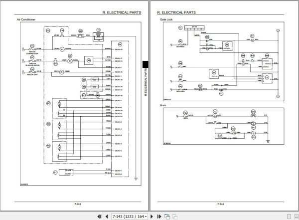
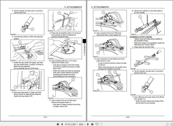
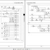
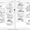


 Automotive - Heavy Equipment - Truck & Bus - Forklift - Crane