
24 ITEMSVIEW CART


Total: 940.00

Expert Support
Full Speed
100% Working
50 USD
Contents:
Excavadora
Seguridad
Seguridad, Información General Y Datos De Par De Apriete Estándar
Información General
Datos De Pares De Apriete Estándar Para Tornillos Y Tuercas
Especificaciones Y Ajustes De Pares De Aprietes Especiales
A. Descenso
Tabla De Equipos Principales
Estructura Y TeorÃa De Funcionamiento De Los Equipos Principales
Diagrama De Lumbreras
Funciones Básicas
Retiro E Instalación De La Oruga
Retiro E Instalación Del Rodillo
Retiro E Instalación De La Rueda Dentada Impulsora
Retiro E Instalación Del Rodillo De Recogida
Armado Y Desarmado Del Rodillo De Recogida
Retiro E Instalación Del Cilindro De Engrase
Armado Y Desarmado Del Amortiguador De Tensión
Retiro E Instalación De La Junta Central
Armado Y Desarmado De La Junta Central
Retiro E Instalación Del Motor De Propulsión
Armado Y Desarmado Del Motor De Propulsión (Natbesco)
Estándares De Mantenimiento
Procedimientos De Medición Y Ajuste De Presión
Procedimientos De Medición Del Volumen De Vaciado
Procedimiento De Purga De Aire
B. C. Unidad De Giro, Contrapeso
Tabla De Equipos Principales
Estructura Y TeorÃa De Funcionamiento De Los Equipos Principales
Diagrama De Lumbreras
Funciones Básicas
Retiro E Instalación De La Unidad De Giro
Armado Y Desarmado Del Motor De Giro
Armado Y Desarmado De La Unidad De Giro
Armado Y Desarmado De La Engranaje Reductor De Giro
Retiro E Instalación Del Contrapeso
Procedimientos De Medición Y Ajuste De Presión
Procedimientos De Medición Del Volumen De Vaciado
Procedimiento De Purga De Aire
H. Motor
Tabla De Equipos Principales
Funciones Básicas
Datos Principales
Función, Estructura Y Funcionamientos
SÃntoma
Inspección De Funcionamiento
Precauciones De Mantenimiento
Retiro E Instalación Del Conjunto De Motor
Retiro E Instalación Del Enfriador De Combustible, Enfriador Del Aire De Carga Del Motor, Radiador Y Enfriador De Aceite
Retiro E Instalación Del Conjunto De Turbocompresor
Inspección Del Filtro De Aire
Retiro E Instalación De La Válvula De Egr
Retiro E Instalación De La Cubierta Superior
Retiro E Instalación Del Silenciador
Retiro E Instalación De La Cubierta De Culata
Retiro E Instalación Del Bloque De Motor
Sistema De Lubricación
Sistema De Enfriamiento
Retiro E Instalación Del Múltiple De Escape
Retiro E Instalación Del Múltiple De Admisión
Retiro E Instalación Del Cigüeñal
Retiro E Instalación Del Pistón Y La Biela
Retiro E Instalación Del Ãrbol De Levas
Retiro E Instalación Del Volante
Retiro E Instalación Del Sello De Aceite Delantero Del Cigüeñal
Retiro E Instalación Del Sello De Aceite Trasero Del Cigüeñal
Retiro E Instalación De La Cadena De Distribución
Retiro E Instalación Del Tren De Engranajes De Distribución
Retiro E Instalación De La Caja De Engranajes De Distribución
Retiro E Instalación Del Eje De Balancines
Retiro E Inspección Del Sello De Aceite Del Vástago De La Válvula Y Del Resorte De La Válvula
Retiro E Instalación Del Depósito De Combustible
Retiro E Instalación De La Bomba De Suministro De Combustible
Retiro E Instalación Del Conjunto Del Múltiple De Inyección Común
Retiro E Instalación Del Inyector
Retiro E Instalación Del Filtro De Combustible
Retiro E Instalación De La Válvula De Descarga
Retiro E Instalación Del Arrancador
Retiro E Instalación Del Alternador
Sistema De Precalentamiento
GuÃa Para El Diagnóstico De Problemas
J. Equipos Hidráulicos (Bomba, Válvula Del Sistema De Funcionamiento)
Tabla De Equipos Principales
Funciones Básicas
Diagrama De Lumbreras
Dispositivo Hidráulico
Estructura Y TeorÃa De Funcionamiento De Los Equipos Principales
Válvula De Control
TeorÃa De Funcionamiento De La Válvula De Solenoide De 4 Tubos
Válvula Piloto Superior (Válvula De Control Remoto)
Válvula Piloto De Propulsión (Válvula De Control Remoto)
Válvula Amortiguadora
Operaciones De Purga De Presión
Retiro E Instalación Del Depósito De Aceite Hidráulico
Retiro E Instalación De La Bomba Hidráulica
Retiro E Instalación Del Acoplamiento De La Bomba
Retiro E Instalación De La Válvula De Control
Retiro E Instalación De Los Bloques Piloto
Retiro E Instalación De La Válvula De Control Remoto De Propulsión
Retiro E Instalación De La Válvula De Control Remoto De Funcionamiento
Retiro E Instalación De La Válvula De Solenoide De 4 Tubos
Retiro E Instalación De La Válvula Amortiguadora
Procedimientos De Armado Y Desarmado De La Unidad Principal De La Bomba Hidráulica
Estándares De Mantenimiento De La Unidad Principal De La Bomba
TeorÃa Del Funcionamiento Del Regulador
Procedimientos De Armado Y Desarmado De La Válvula De Control
Procedimientos De Armado Y Desarmado De La Válvula De Control Remoto De Funcionamiento
Procedimientos De Armado Y Desarmado De La Válvula De Control Remoto De Propulsión
Armado Y Desarmado De La Válvula Amortiguadora
Procedimientos De Medición Y Ajuste De Presión
Procedimientos De Medición Del Caudal De La Bomba Hidráulica
Procedimiento De Purga De Aire
Disposición De Equipos Hidráulicos
Vista General
N. Cabina
Retiro E Instalación Del Asiento Del Operador
Retiro E Instalación Del Conjunto De Cabina
Retiro E Instalación Del Limpiaparabrisas
Retiro E Instalación Del Vidrio Delantero De La Cabina
Procedimientos De Ajuste De Bloqueo De La Ventana
Par De Apriete
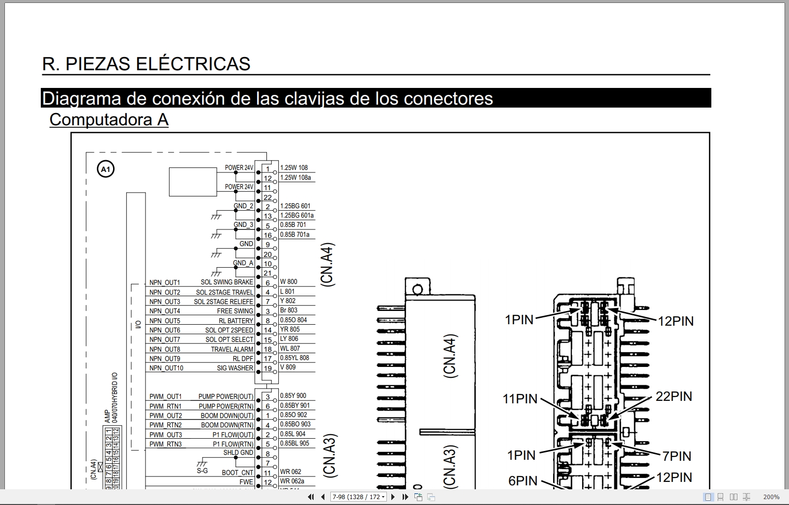
R. Piezas Eléctricas
Funciones Eléctricas Y Del Motor Y Apoyo De Mantenimiento
Funciones Básicas
Accesorios
Interruptor De Desconexión De BaterÃa
Restauración
Lista De Miliamperios
Seguridad
Service Support
Configuración
Monitor De Servicio
Explicación De La Computadora
Diagrama De Conexión De Las Clavijas De Los Conectores
Diagrama Del Circuito De Secuencia
Diagrama De Disposición De Los Equipos Eléctricos
Retiro E Instalación Del Controlador Del Limpiaparabrisas
Retiro E Instalación Del Motor Del Limpiaparabrisas
Retiro E Instalación Del Monitor
Retiro E Instalación De La Cámara Retrovisora
Retiro E Instalación De La Cámara Lateral (Derecha)
Procedimiento De Sustitución Del Ecm
Retiro E Instalación Del Ecm
Retiro E Instalación De La Computadora A
Retiro E Instalación De La Computadora B
Diagrama General Del Acondicionador De Aire
Armado Y Desarmado De La Unidad
Retiro E Instalación Del Compresor
Retiro E Instalación Del Condensador
Retiro E Instalación Del Secador Acumulador
Precauciones Para Los Procedimientos
V. Accesorios
Tabla De Equipos Principales
Estándares De Mantenimiento
Retiro E Instalación Del Cilindro Del Cucharón
Retiro E Instalación Del Cilindro Del Brazo
Retiro E Instalación Del Cilindro De La Pluma
Procedimientos De Funcionamiento Y Armado/Desarmado Del Cilindro Hidráulico (Realizados Por Kyb)
Diagrama De Lumbreras
Retiro E Instalación De La Hbcv
Procedimiento De Purga De Aire
Retiro E Instalación Del Cucharón
Retiro E Instalación Del Varillaje Del Cucharón
Retiro E Instalación Del Brazo
Retiro E Instalación De La Pluma
Z. Otros
Especificaciones
Dimensión Del Brazo
Peso De La Unidad Principal
Tabla De Tamaños Y Pares De Apriete De Pernos
Vista General
Diagrama De Rango De Funcionamiento
Fluidos Y Lubricantes
Lista De Códigos De Diagnóstico De Problemas En El Lateral De La Unidad Principal
Problema En El Lateral De La Unidad Principal
Lista De Herramientas Especiales
Contents:
Excavator
Safety
Safety, General Information, and Standard Torque Data
General Information
Standard Torque Data for Bolts and Nuts
Special Torque Specifications and Settings
A. Lowering
Main Equipment Table
Main Equipment Structure and Theory of Operation
Port Diagram
Basic Functions
Track Removal and Installation
Roller Removal and Installation
Drive Sprocket Removal and Installation
Pickup Roller Removal and Installation
Pickup Roller Assembly and Disassembly
Grease Cylinder Removal and Installation
Tension Damper Assembly and Disassembly
Center Joint Removal and Installation
Center Joint Assembly and Disassembly
Propulsion Motor Removal and Installation
Propulsion Motor Assembly and Disassembly (Natbesco)
Maintenance Standards
Procedures Pressure Measurement and Adjustment
Vacuum Volume Measurement Procedures
Air Bleeding Procedure
B. C. Swing Unit, Counterweight
Main Equipment Table
Structure and Theory of Operation of Main Equipment
Port Diagram
Basic Functions
Removal and Installation of the Swing Unit
Assembly and Disassembly of the Swing Motor
Assembly and Disassembly of the Swing Unit
Assembly and Disassembly of the Swing Reduction Gear
Removal and Installation of the Counterweight
Pressure Measurement and Adjustment Procedures
Vacuum Volume Measurement Procedures
Air Bleeding Procedure
H. Engine
Main Equipment Table
Basic Functions
Main Data
Function, Structure, and Operations
Symptom
Operational Inspection
Maintenance Precautions
Removal and Installation of the Engine Assembly
Removal and Installation of the Fuel Cooler, Engine Charge Air Cooler, Radiator, and Oil Cooler
Turbocharger Assembly Removal and Installation
Air Filter Inspection
EGR Valve Removal and Installation
Top Cover Removal and Installation
Muffler Removal and Installation
Cylinder Head Cover Removal and Installation
Engine Block Removal and Installation
Lubrication System
Cooling System
Exhaust Manifold Removal and Installation
Intake Manifold Removal and Installation
Crankshaft Removal and Installation
Piston and Connecting Rod Removal and Installation
Camshaft Removal and Installation
Flywheel Removal and Installation
Crankshaft Front Oil Seal Removal and Installation
Crankshaft Rear Oil Seal Removal and Installation
Timing Chain Removal and Installation
Timing Geartrain Removal and Installation Timing
Rocker Arm Shaft Removal and Installation
Valve Stem Oil Seal and Valve Spring Removal and Inspection
Fuel Tank Removal and Installation
Fuel Supply Pump Removal and Installation
Common Rail Injection Manifold Assembly Removal and Installation
Injector Removal and Installation
Fuel Filter Removal and Installation
Unloader Valve Removal and Installation
Starter Removal and Installation
Alternator Removal and Installation
Preheating System
Troubleshooting Guide
J. Hydraulic Equipment (Pump, Valve, Operating System)
Main Equipment Table
Basic Functions
Port Diagram
Hydraulic Device
Structure and Operating Theory of Main Equipment
Control Valve
4-Pipe Solenoid Valve Operating Theory
Overhead Pilot Valve (Remote Control Valve)
Propulsion Pilot Valve (Remote Control Valve)
Cushion Valve
Pressure Bleeding Operations
Removal and Installation of the Hydraulic Oil Reservoir
Removal and Installation of the Hydraulic Pump
Removal and Installation of the Pump Coupling
Removal and Installation of the Control Valve
Removal and Installation of the Pilot Blocks
Removal and Installation of the Propulsion Remote Control Valve
Removal and Installation of the Operating Remote Control Valve
Removal and Installation of the 4-Pipe Solenoid Valve
Removal and Installation of the Cushion Valve
Assembly and Disassembly Procedures for the Hydraulic Pump Main Unit
Maintenance Standards for the Pump Main Unit
Governor Theory of Operation
Assembly and Disassembly Procedures for the Control Valve
Assembly and Disassembly of the Remote Control Valve
Assembly and Disassembly Procedures for the Propulsion Remote Control Valve
Assembly and Disassembly of the Damping Valve
Pressure Measurement and Adjustment Procedures
Procedures Hydraulic Pump Flow Measurement
Air Bleeding Procedure
Hydraulic Equipment Layout
Overview
Cab
Operator’s Seat Removal and Installation
Cab Assembly Removal and Installation
Windshield Wiper Removal and Installation
Front Cab Glass Removal and Installation
Window Lock Adjustment Procedures
Tightening Torque
Electrical Parts
Electrical and Motor Functions and Maintenance Support
Basic Functions
Accessories
Battery Disconnect Switch
Reset
Milliamp List
Safety
Service Support
Configuration
Service Monitor
Computer Explanation
Connector Pin Connection Diagram
Sequence Circuit Diagram
Electrical Equipment Layout Diagram
Wiper Controller Removal and Installation
Wiper Motor Removal and Installation
Monitor Removal and Installation
Rearview Camera Removal and Installation
Side Camera Removal and Installation (Right)
ECM Replacement Procedure
ECM Removal and Installation
Computer A Removal and Installation
Computer B Removal and Installation
Air Conditioner General Diagram
Unit Assembly and Disassembly
Compressor Removal and Installation
Condenser Removal and Installation
Accumulator Dryer Removal and Installation
Procedure Precautions
V. Accessories
Main Equipment Table
Maintenance Standards
Bucket Cylinder Removal and Installation
Arm Cylinder Removal and Installation
Boom Cylinder Removal and Installation
Hydraulic Cylinder Operating and Assembly/Disassembly Procedures (Performed by KYB)
Port Diagram
HBCV Removal and Installation
Air Bleeding Procedure
Removal and Installation of Bucket
Bucket Linkage Removal and Installation
Stick Removal and Installation
Boom Removal and Installation
Z. Others
Specifications
Stick Dimensions
Main Unit Weight
Bolt Size and Torque Table
Overview
Operating Range Diagram
Fluids and Lubricants
List of Diagnostic Trouble Codes on the Side of the Main Unit
Problem on the Side of the Main Unit
List of Special Tools

REALEASE :
REALEASE :

REALEASE :
21.09.2021
REALEASE :
21.09.2021
REALEASE :
REALEASE :
REALEASE :
REALEASE :
REALEASE :
REALEASE :
REALEASE :
REALEASE :

REALEASE :
REALEASE :
REALEASE :
REALEASE :
 Automotive - Heavy Equipment - Truck & Bus - Forklift - Crane