
0 ITEMSVIEW CART


✓
Expert Support
✓
Full Speed
✓
100% Working
Link-Belt Excavator 145X4 DZ, 145X4 LC Service Manual WLSM4706-08LX-FR
Size: 99.47 MB
Format: PDF
Language: French
Brand: Link-Belt
Type of Machine: Excavator
Type of Manual: Service Manual, Electrical Schematic
Model: Link-Belt 145X4 DZ ; 145X4 LC Excavator
Part Number: WLSM4706-08LX-FR
Publication Date: 2019
Number of Pages: 2137 Pages
50 USD
- Description
Description
Contents:
Excavatrice
Sécurité
Sécurité, Informations Générales Et Couples De Serrage Standard
Informations Générales
Couples De Serrage Standard Des Vis Et Des Écrous
Protection Du Systéme Électrique / Électronique Pendant La Recharge Ou La Soudure
A. Inférieur
Tableau De L’équipement Principal
Structure Et Principe De Fonctionnement De L’équipement Principal
Schéma D’orifices
Fonctions De Base
Retrait Et Installation De La Chenille
Retrait Et Installation Du Galet
Retrait Et Installation De La Roue Dentée D’entraînement
Retrait Et Installation Du Galet Tendeur
Montage Et Démontage Du Galet Tendeur
Retrait Et Installation Du Vérin De Graissage
Montage Et Démontage Des Amortisseurs De Tension
Retrait Et Installation De L’articulation Centrale
Montage Et Démontage De L’articulation Centrale
Retrait Et Installation Du Moteur De Déplacement
Montage Et Démontage Du Moteur De Déplacement (Nabtesco)
Valeurs Standard De Maintenance
Procédures De Mesure Et De Réglage De La Pression
Procédures De Mesure Du Volume De Vidange
Procédure De Purge D’air
B. C. Unité De Pivotement, Contrepoids
Tableau De L’équipement Principal
Structure Et Principe De Fonctionnement De L’équipement Principal
Schéma D’orifices
Fonctions De Base
Retrait Et Installation De L’unité De Pivotement
Montage Et Démontage Du Moteur Et Du Réducteur De Rotation
Retrait Et Installation Du Contrepoids
Procédures De Mesure Et De Réglage De La Pression
Procédures De Mesure Du Volume De Vidange
Procédure De Purge D’air
H. Moteur
Tableau De L’équipement Principal
Fonctions De Base
Spécifications Principales
Fonction, Structure, Fonctionnement
Fonction, Structure, Fonctionnement (Scr)
Inspection Du Système De Commande Du Scr
Explication Du Fonctionnement Du Scr
Diagnostic Pour Chaque Symptôme
Diagnostic Pour Chaque Symptôme
Inspection Fonctionnelle
Retrait Et Installation Du Moteur
Retrait Et Installation Du Refroidisseur De Carburant, Refroidisseur D’air De Suralimentation Du Moteur, Radiateur Et Refroidisseur D’huile
Retrait Et Installation Du Turbocompresseur
Retrait Et Installation De La Soupape Egr (Le Cas Échéant)
Retrait Et Installation Du Refroidisseur Egr
Retrait Et Installation Du Capot Du Moteur
Retrait Et Installation Du Scr
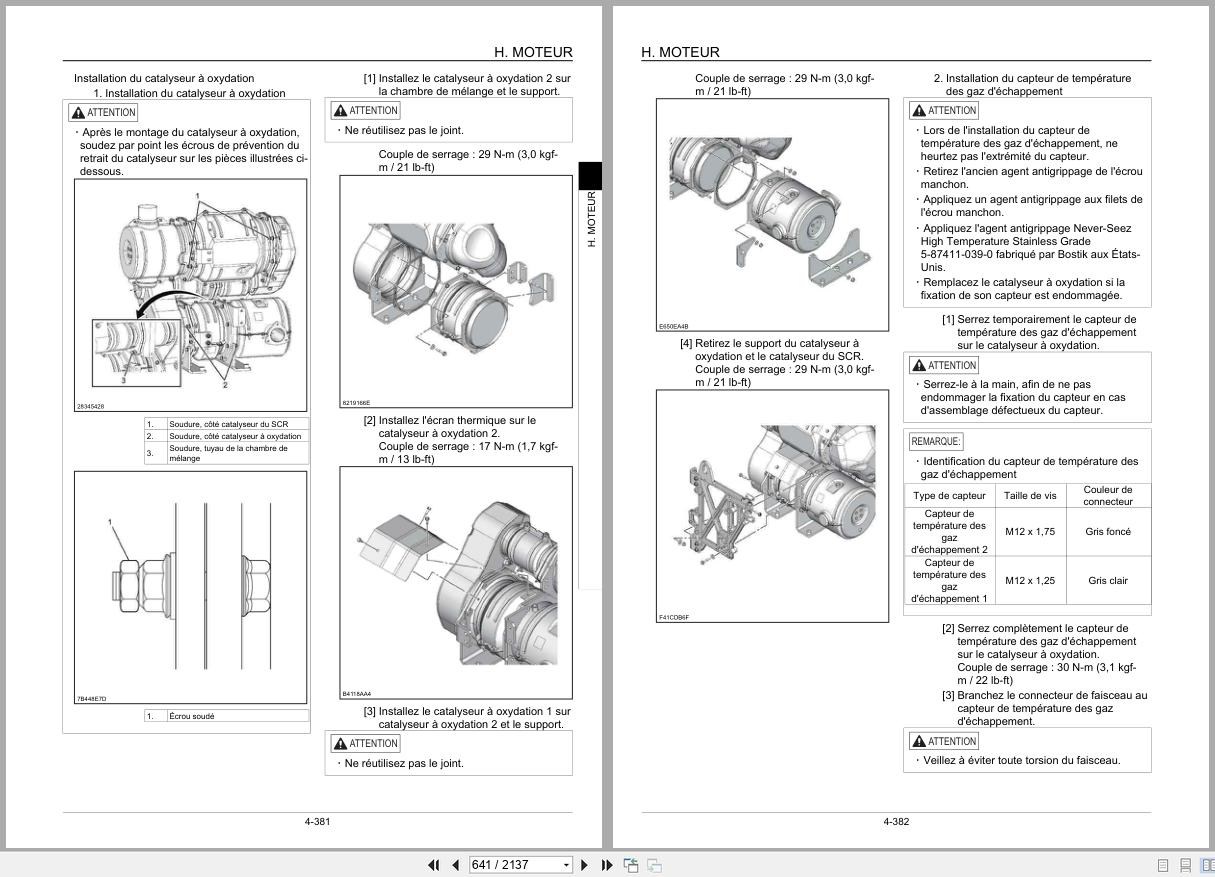
Retrait Et Installation Du Catalyseur Scr
Retrait Et Installation Du Couvercle De Culasse
Retrait Et Installation Du Bloc-Cylindres
Circuit De Lubrification
Circuit De Refroidissement
Système D’induction
Système D’échappement
Aux Système Des Appareils De Contrôle Des Émissions Aux.
Retrait Et Installation Du Collecteur D’échappement
Retrait Et Installation Du Réservoir De Carburant
Retrait Et Installation De La Pompe D’urée
Retrait Et Installation Du Réservoir À Solutions D’urée
Retrait Et Installation De La Pompe D’alimentation En Carburant
Retrait Et Installation De La Rampe Commune
Retrait Et Installation De L’injecteur
Retrait Et Installation Du Vilebrequin
Retrait Et Installation Du Piston Et De La Tringlerie
Retrait Et Installation De L’arbre À Cames
Retrait Et Installation Du Volant Moteur
Retrait Et Installation Du Joint D’huile Avant Du Vilebrequin
Retrait Et Installation Du Joint D’huile Arrière De Vilebrequin
Retrait Et Installation De La Chaîne De Distribution
Retrait Et Installation Du Train D’engrenages De Distribution
Retrait Et Installation Du Carter D’engrenages De Distribution
Retrait Et Installation Du Collecteur D’admission
Retrait Et Installation De L’axe De Culbuteurs
Retrait Et Inspection Du Joint D’huile De La Tige De Soupape Et Du Ressort De Soupape
Retrait Et Installation Du Papillon D’admission
Retrait Et Installation Du Démarreur
Retrait Et Installation De L’alternateur
Retrait Et Installation D’une Bougie De Préchauffage
Retrait Et Installation De La Vanne D’aspiration
Retrait Et Installation Du Filtre À Carburant
Retrait Et Installation Du Clapet De Décharge
Retrait Et Installation De L’élément De Filtre À Carburant
Retrait Et Installation Du Capteur De Température De Carburant
Retrait Et Installation Du Limiteur De Pression
Retrait Et Installation Du Capteur De Pression De Carburant
Retrait Et Installation Du Capteur De Pression Du Filtre À Carburant
Retrait Et Installation Du Capteur De Température Du Liquide De Refroidissement Moteur
Retrait Et Installation Du Capteur De Position Du Vilebrequin
Retrait Et Installation Du Capteur De Position De L’arbre À Cames
Retrait Et Installation Du Capteur De Pression D’huile
Retrait Et Installation Du Capteur De Suralimentation
Retrait Et Installation Du Capteur De Température De Suralimentation
Retrait Et Installation Du Solénoïde De Commande Du Turbocompresseur
Retrait Et Installation Du Capteur De Température Du Collecteur D’admission
Retrait Et Installation Des Capteurs De Débit Massique Et De Température D’air D’admission
Retrait Et Installation Du Capteur De Température De L’échangeur Thermique 1
Procédure D’échantillonnage
Retrait Et Installation Du Capteur De Température Des Gaz D’échappement
Retrait Et Installation Du Capteur De Température Des Gaz Réinjectés 1
Retrait Et Installation Du Capteur De Température Des Gaz Réinjectés 2
Retrait Et Installation Du Capteur De Nox
Retrait Et Installation Du Capteur De Température Des Gaz Réinjectés 3
Retrait Et Installation Du Capteur De Fed
Liste Des Codes D’anomalie Relatifs Au Moteur
Anomalie Côté Moteur
Valeurs De Référence De Données
J. Équipement Hydraulique (Pompe, Vanne De Système De Fonctionnement)
Tableau De L’équipement Principal
Fonctions De Base
Schéma D’orifices
Pompe Hydraulique
Distributeur
Principe De Fonctionnement De L’électrovanne À 4 Tiroirs Empilables
Distributeur Pilote De Superstructure (Distributeur À Distance)
Distributeur Pilote De Déplacement (Distributeur À Distance)
Vanne À Amortisseur
Sélecteur (Bidirectionnel)
Vanne De Direction (À 3 Voies)
Clapet De Décharge Électromagnétique
Retrait Et Installation Du Réservoir Hydraulique
Retrait Et Installation De La Pompe Hydraulique
Retrait Et Installation De L’accouplement De La Pompe
Retrait Et Installation Du Distributeur
Retrait Et Installation Du Distributeur À Distance De Déplacement
Retrait Et Installation Du Distributeur À Distance
Retrait Et Installation Du Solénoïde À 4 Tiroirs Empilables
Retrait Et Installation De La Vanne À Amortisseur
Dépose Et Installation De Vanne Réducteur À 4 Tiroirs
Procédures De Montage Et De Démontage De L’unité De Pompe Hydraulique Principale
Valeurs Standard De Maintenance De L’unité De Pompe Principale
Causes De Défaillances, Et Actions
Procédures De Montage Et De Démontage Du Distributeur
Procédures De Montage Et De Démontage Du Distributeur À Distance
Procédures De Montage Et De Démontage Du Distributeur À Distance De Déplacement
Montage Et Démontage De La Vanne À Amortisseur
Procédures De Mesure Et De Réglage De La Pression
Procédures De Mesure Du Débit De Pompe Hydraulique
Procédure De Purge D’air
Procédure D’échantillonnage
Disposition De L’équipement Hydraulique
Vue Générale
N. Cabine
Retrait Et Installation Du Siège De L’opérateur
Retrait Et Installation De La Cabine
Retrait Et Installation De L’essuie-Glace
Dépose Et Installation Du Parebrise De La Cabine
Procédure De Réglage Du Verrou De Fenêtre
Retrait Et Installation De La Main Courante Du Carter
Couple De Serrage
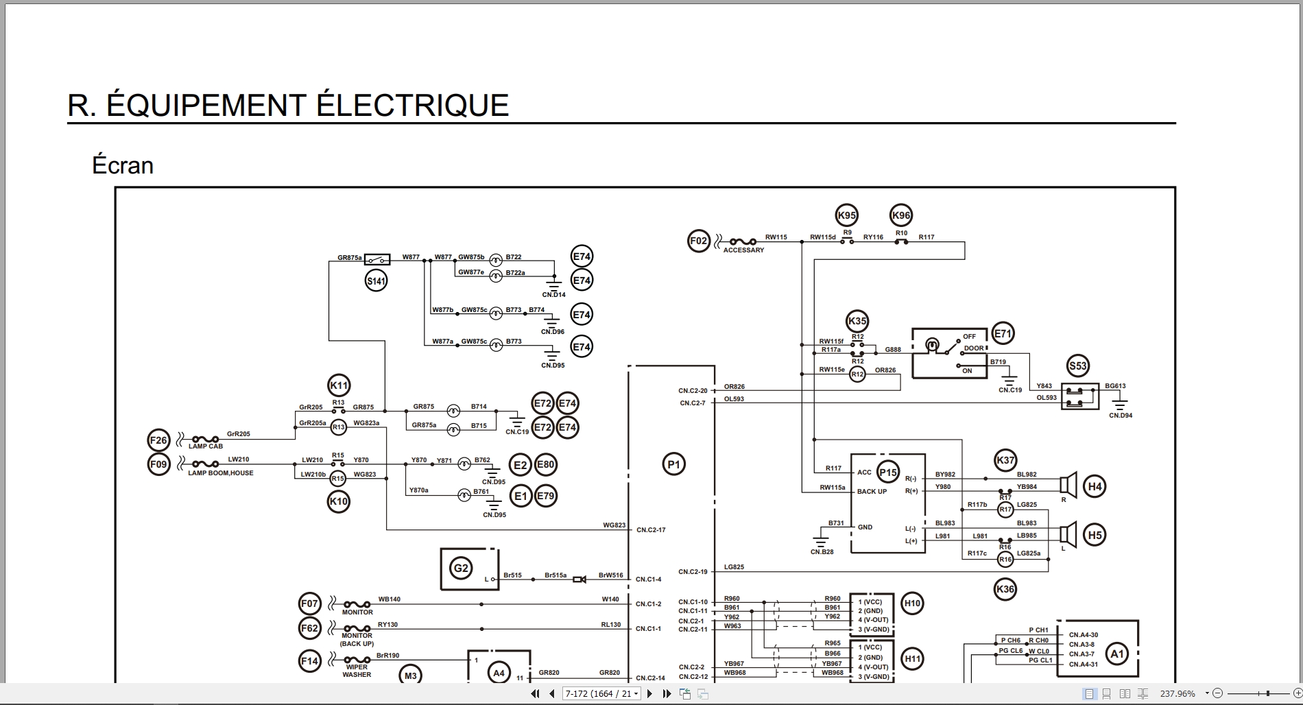
R. Équipement Électrique
Fonctions De Base
Support D’entretien
Brochage Des Connecteurs
Schéma Du Circuit De Séquence
Schéma De Disposition De L’équipement Électrique
Retrait Et Installation Du Système De Commande D’essuie-Glace
Retrait Et Installation Du Moteur D’essuie-Glace
Retrait Et Installation De L’ecm
Retrait Et Installation Du Système De Commande Principal
Retrait Et Installation De L’unité Dcu
Retrait Et Installation De L’écran
Retrait Et Installation De La Caméra De Recul
Dépose Et Installation De La Caméra Latérale (Droite)
Retrait Et Installation De La Caméra Latérale (Gauche)
Dépose Et Installation D’éclairage D’ambiance
Dépose Et Installation Du Contrôleur Waves
Voir “Comment Régler Le Waves”.
Schéma Général Du Climatiseur
Montage Et Démontage De L’unité
Retrait Et Installation Du Compresseur
Retrait Et Installation Du Condenseur
Retrait Et Installation Du Réservoir Déshydrateur
Précautions Concernant Le Travail
V. Accessoires
Tableau De L’équipement Principal
Valeurs Standard De Maintenance
Retrait Et Installation Du Vérin De Godet
Retrait Et Installation Du Vérin De Bras
Retrait Et Installation Du Vérin De Flèche
Retrait Et Installation Du Vérin De Lame
Procédures De Fonctionnement/Montage Et Démontage Du Vérin Hydraulique
Clapet Antiretour Contre L’éclatement Des Flexibles
Schéma D’orifices
Procédure De Purge D’air
Retrait Et Installation Du Hbcv
Retrait Et Installation Du Clapet Antiretour Contre L’éclatement Des Flexibles Du Bras
Retrait Et Installation Du Hbcv De La Flèche
Retrait Et Installation Du Godet
Retrait Et Installation De La Tringlerie De Godet
Retrait Et Installation Du Bras
Retrait Et Installation De La Flèche
Retrait Et Installation De La Lame
Z. Autre
Changement Du Type 6
Spécifications (145×4) (Spécifications Lc)
Spécifications (145×4) (Spécifications De Lame)
Dimensions De Bras
Poids De L’unité Principale
Tableau De Taille Et De Couple De Serrage Des Boulons
Vue Générale
Schéma De Plage De Fonctionnement
Tableau D’évaluation Des Performances D’une Machine Neuve
Liquides Et Lubrifiants
Liste Des Codes D’anomalie Concernant L’unité Principale
Anomalie Côté Unité Principale
Liste Des Outils Spéciaux
Couleurs De Peinture
Abréviation
Contents:
Excavator
Safety
Safety, General Information, and Standard Tightening Torques
General Information
Standard Tightening Torques for Screws and Nuts
Protection of the Electrical/Electronic System During Recharging or Welding
A. Lower
Main Equipment Table
Main Equipment Structure and Working Principle
Hole Diagram
Basic Functions
Removal and Installation of the Track
Removal and Installation of the Roller
Removal and Installation of the Drive Sprocket
Removal and Installation of the Idler Pulley
Assembly and Disassembly of the Idler Pulley
Removal and Installation of the Grease Cylinder
Assembly and Disassembly of the Tension Dampers
Removal and Installation of the Center Joint
Assembly and Disassembly of the Center Joint
Removal and Installation of the Travel Motor
Assembly and Disassembly of the Travel Motor (Nabtesco)
Standard Maintenance Values
Measurement and Testing Procedures Pressure Adjustment
Drain Volume Measurement Procedures
Air Bleeding Procedure
B. C. Swing Unit, Counterweight
Main Equipment Table
Structure and Operating Principle of the Main Equipment
Port Diagram
Basic Functions
Removal and Installation of the Swing Unit
Assembly and Disassembly of the Motor and Swing Reducer
Removal and Installation of the Counterweight
Pressure Measurement and Adjustment Procedures
Drain Volume Measurement Procedures
Air Bleeding Procedure
H. Engine
Main Equipment Table
Basic Functions
Main Specifications
Function, Structure, Operation
Function, Structure, Operation (SCR)
Inspection of the SCR Control System
Explanation of SCR Operation
Diagnosis for Each Symptom
Diagnosis for Each Symptom
Functional Inspection
Removal and Installation of the Engine
Removal and Installation of the Fuel Cooler, Engine Charge Air Cooler, Radiator, and Oil Cooler
Turbocharger Removal and Installation
EGR Valve Removal and Installation (If Equipped)
EGR Cooler Removal and Installation
Engine Cover Removal and Installation
SCR Removal and Installation
SCR Catalyst Removal and Installation
Cylinder Head Cover Removal and Installation
Cylinder Block Removal and Installation
Lubrication System
Cooling System
Induction System
Exhaust System
Aux Emission Control Devices System
Exhaust Manifold Removal and Installation
Fuel Tank Removal and Installation
Urea Pump Removal and Installation
Urea Solution Tank Removal and Installation
Fuel Feed Pump Removal and Installation
Common Rail Removal and Installation
Injector Removal and Installation
Crankshaft Removal and Installation
Piston and Linkage Removal and Installation
Camshaft Removal and Installation
Flywheel Removal and Installation
Crankshaft Front Oil Seal Removal and Installation
Crankshaft Rear Oil Seal Removal and Installation
Timing Chain Removal and Installation
Timing Gear Set Removal and Installation
Timing Gear Cover Removal and Installation
Intake Manifold Removal and Installation
Rocker Arm Shaft Removal and Installation
Valve Stem Oil Seal and Valve Spring Removal and Inspection
Removal and Installation of the Intake Throttle Valve
Removal and Installation of the Starter Motor
Removal and Installation of the Alternator
Removal and Installation of a Glow Plug
Removal and Installation of the Intake Valve
Removal and Installation of the Fuel Filter
Removal and Installation of the Wastegate
Removal and Installation of the Fuel Filter Element
Removal and Installation of the Fuel Temperature Sensor
Removal and Installation of the Pressure Relief Valve
Removal and Installation of the Fuel Pressure Sensor
Removal and Installation of the Fuel Filter Pressure Sensor
Removal and Installation of the Engine Coolant Temperature Sensor
Removal and Installation of the Crankshaft Position Sensor
Removal and Installation of the Camshaft Position Sensor
Removal and Installation of the Oil Pressure Sensor
Removal and Installation of the Boost Sensor
Removal and Installation of the Boost Temperature Sensor
Removal and Installation of the Turbocharger Control Solenoid
Removing and Installing the Intake Manifold Temperature Sensor
Removing and Installing the Mass Air Flow and Intake Air Temperature Sensors
Removing and Installing the Intake Manifold Temperature Sensor
Heat Exchanger Structure 1
Sampling Procedure
Exhaust Gas Temperature Sensor Removal and Installation
Recirculation Gas Temperature Sensor Removal and Installation 1
Recirculation Gas Temperature Sensor Removal and Installation 2
NOx Sensor Removal and Installation
Recirculation Gas Temperature Sensor Removal and Installation 3
EDF Sensor Removal and Installation
Engine-Related Trouble Code List
Engine-Side Fault
Data Reference Values
J. Hydraulic Equipment (Pump, Operating System Valve)
Main Equipment Table
Basic Functions
Port Diagram
Hydraulic Pump
Control Valve
Operating Principle of 4-Spool Stackable Solenoid Valve
Superstructure Pilot Valve (Remote Valve)
Displacement Pilot Valve (Remote Valve)
Damper Valve
Selector Valve (Bidirectional)
Direction Valve (Two-Way) 3-Way
Solemagnetic Relief Valve
Hydraulic Reservoir Removal and Installation
Hydraulic Pump Removal and Installation
Pump Coupling Removal and Installation
Directional Valve Removal and Installation
Remote Travel Valve Removal and Installation
Remote Valve Removal and Installation
Stackable 4-Spool Solenoid Removal and Installation
Damper Valve Removal and Installation
4-Spool Reducer Valve Removal and Installation
Main Hydraulic Pump Unit Removal and Disassembly Procedures
Main Pump Unit Maintenance Standards
Causes of Failure and Actions
Directional Valve Removal and Disassembly Procedures
Remote Valve Removal and Disassembly Procedures
Damper Valve Removal and Installation
Pressure Measurement and Adjustment Procedures
Hydraulic Pump Flow Measurement Procedures
Air Bleeding Procedure
Sampling Procedure
Hydraulic Equipment Layout
Overview
Cab No.
Operator Seat Removal and Installation
Cab Removal and Installation
Windshield Wiper Removal and Installation
Cab Windshield Removal and Installation
Window Lock Adjustment Procedure
Housing Handrail Removal and Installation
Tightening Torque
Electrical Equipment
Basic Functions
Maintenance Support
Connector Pinouts
Sequence Circuit Diagram
Electrical Equipment Layout Diagram
Wiper Control System Removal and Installation
Wiper Motor Removal and Installation
ECM Removal and Installation
Main Control System Removal and Installation
DCU Removal and Installation
Display Removal and Installation
Rearview Camera Removal and Installation
Camera Removal and Installation Side (Right)
Removing and Installing the Side (Left) Camera
Removing and Installing the Ambient Lighting
Removing and Installing the Waves Controller
See ​​”How to Set Up the Waves.”
General Diagram of the Air Conditioner
Unit Assembly and Disassembly
Compressor Removal and Installation
Condenser Removal and Installation
Receiver Drier Removal and Installation
Work Precautions
V. Attachments
Main Equipment Table
Standard Maintenance Values
Bucket Cylinder Removal and Installation
Arm Cylinder Removal and Installation
Boom Cylinder Removal and Installation
Blade Cylinder Removal and Installation
Hydraulic Cylinder Operating Procedures/Assembly and Disassembly
Hose Burst Check Valve
Port Diagram
Air Bleeding Procedure
HBVC Removal and Installation
Arm Hose Burst Check Valve Removal and Installation
Boom HBVC Removal and Installation
Bucket Removal and Installation
Bucket Linkage Removal and Installation
Arm Removal and Installation
Hydraulic Cylinder Removal and Installation Arrow
Blade Removal and Installation
Z. Other
Type 6 Changeover
Specifications (145×4) (Lc Specifications)
Specifications (145×4) (Blade Specifications)
Arm Dimensions
Main Unit Weight
Bolt Size and Tightening Torque Chart
General View
Operating Range Diagram
New Machine Performance Evaluation Chart
Fluids and Lubricants
Main Unit Fault Code List
Main Unit Side Fault
Special Tools List
Paint Colors
Abbreviation
Related Products
-
Link-Belt Rubber Tiered Material Handler 360X2 Shop Manual
30 USDSize: 39.00 MBFormat: PDFLanguage: EnglishBrand: Link-BeltType of Machine: Material HandlerType of Manual: Shop Manual, Hydraulic And Electrical SchematicModel: Link-Belt 360X2 Material HandlerEngine: Isuzu 6HK1XYSS Diesel EngineNumber of Pages: 755 Pages
REALEASE :
REALEASE :
-
Link-Belt Wheel Loader L125 Service Manual Electrical Schematic
40 USDSize: 97.03 MBFormat: PDFLanguage: EnglishBrand: Link-BeltType of Machine: Wheel LoaderType of Manual: Service Manual, Electrical SchematicModel: Link-Belt L125 Wheel LoaderEngine: Cummins 6BTA5.9 EngineList of Files:L120WL L125WL Electrical Schematic.pdf (37 Pages)L125 Service Manual 1123.pdf (656 Pages)
REALEASE :
REALEASE :
-
Link-Belt Wheel Loader L130 Service Manual Electrical Schematic
40 USDSize: 87.01 MBFormat: PDFLanguage: EnglishBrand: Link-BeltType of Machine: Wheel LoaderType of Manual: Service Manual, Electrical SchematicModel: Link-Belt L130 Wheel LoaderEngine: Cummins 6BTA5.9 EngineList of Files:L130 Service Manual 1121.pdf (652 Pages)L130 WL Electrical Schematic.pdf (35 Pages)
REALEASE :
REALEASE :
-
Link-Belt Scrap Grapple LSG All Models Safety Operator Manual
15 USDSize: 12.77 MBFormat: PDFLanguage: EnglishBrand: Link-BeltType of Machine: Scrap GrappleType of Manual: Safety And Operator ManualModel: Link-Belt Scrap Grapple LSG All ModelsNumber of Pages: 49 Pages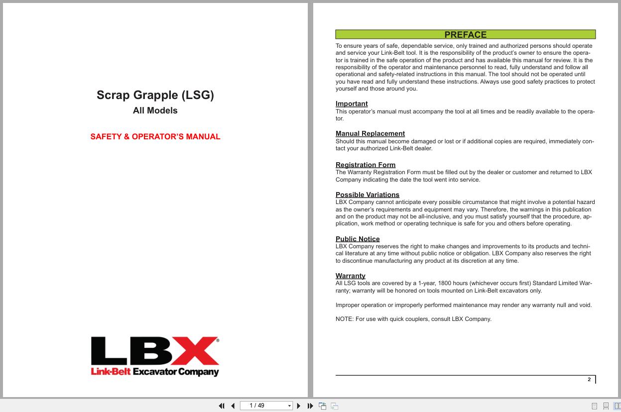
REALEASE :
REALEASE :
-
Link-Belt Wheel Loader L120 Service Manual Electrical Schematic
40 USDSize: 98.22 MBFormat: PDFLanguage: EnglishBrand: Link-BeltType of Machine: Wheel LoaderType of Manual: Service Manual, Electrical SchematicModel: Link-Belt L120 Wheel LoaderEngine: Cummins 4BTA3.9 EngineList of Files:L120 Service Manual 1122.pdf (660 Pages)L120WL L125WL Electrical Schematic.pdf (37 Pages)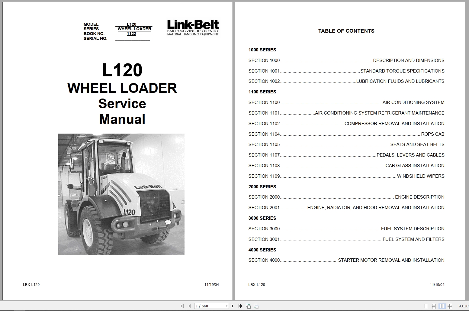
REALEASE :
REALEASE :
-
Link-Belt Scrap Grapple Standard and Heavy-Duty Parts Manual
15 USDSize: 7.09 MBFormat: PDFLanguage: EnglishBrand: Link-BeltType of Machine: Scrap Grapple Standard and Heavy-DutyType of Manual: Parts ManualModel: Link-Belt Scrap Grapple Standard and Heavy-DutyNumber of Pages: 43 Pages
REALEASE :
REALEASE :
-
Linkbelt Excavator, Wheel Loader, Articulated Truck 8.9 GB DVD Shop Manual, Part Manual, Schematic Diagram
Original price was: 200.140Current price is: 140. USDLinkbelt Excavator, Wheel Loader, Articulated Truck 8.9 GB DVD Shop Manual, Part Manual, Schematic DiagramSize: 8.9 GbLanguage: EnglishBrand: LinkbeltType of machine: Linkbelt Excavator, Wheel Loader, Articulated TruckFormat: PDF, IMGType: Shop Manual, Part Manual, Electrical Schematic, Hydraulic SchematicWindow: All Window 32 & 64 bitAmount of DVD: 1 DVD rarHigh-speed Link DownloadHot-30%
REALEASE :
21.09.2021
REALEASE :
21.09.2021
-
Link-Belt Shear Shield LXS Field Installation Manual
10 USDSize: 4.56 MBFormat: PDFLanguage: EnglishBrand: Link-BeltType of Machine: Shear ShieldType of Manual: Field Installation ManualModel: Link-Belt Shear Shield LXSNumber of Pages: 24 Pages
REALEASE :
REALEASE :