
4 ITEMSVIEW CART


Total: 480.00

Expert Support
Full Speed
100% Working
50 USD
Contents:
Excavator
Safety
Safety, General Information And Standard Torque Data
General Information
Standard Torque Data For Cap Screws And Nuts
A. Lower
Main Equipment Table (300×3)
Main Equipment Structure And Operation Explanation
Port Diagram
Basic Functions
Removal And Installation Of Track
Removal And Installation Of Roller
Removal And Installation Of Drive Sprocket
Removal And Installation Of Take-Up Roller
Assembly And Disassembly Of Take-Up Roller
Removal And Installation Of Grease Cylinder
Assembly And Disassembly Of Grease Cylinder
Removal And Installation Of Center Joint
Assembly And Disassembly Of Center Joint
Removal And Installation Of Travel Motor
Assembly And Disassembly Of Travel Motor
Maintenance Standards
Pressure Measurement And Adjustment Procedures
Drain Volume Measurement Procedures
Air Bleed Procedure
B. C. Swing Unit, Counterweight
Main Equipment Table (300×3)
Main Equipment Structure And Operation Explanation
Port Diagram
Basic Functions
Removal And Installation Of Swing Unit
Assembly And Disassembly Of Swing Motor
Assembly And Disassembly Of Swing Unit
Assembly And Disassembly Of Swing Reduction Gear
Removal And Installation Of Counterweight
Pressure Measurement And Adjustment Procedures
Drain Volume Measurement Procedures
Air Bleed Procedure
H. Engine
Main Equipment Table (300×3)
Basic Functions
Main Data
Function, Structure, And Operations
Symptom
Functional Inspection
Cautions For Maintenance
Removal And Installation Of Engine Assembly
Removal And Installation Of Fuel Cooler, Engine Intercooler, Radiator, And Oil Cooler
Removal And Installation Of Turbo Charger
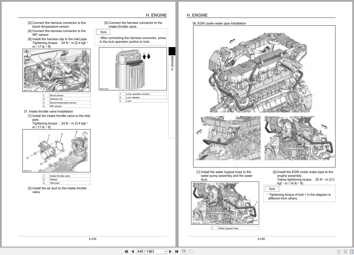
Removal And Installation Of Egr Cooler And Egr Valve
Removal And Installation Of Engine Hood
Removal And Installation Of Dpd (Muffler)
Removal And Installation Of Cylinder Head Cover
Removal And Installation Of Cylinder Block
Lubrication System
Cooling System
Removal And Installation Of Exhaust Manifold
Disassembly, Removal And Installation Of Dpd Assembly
Removal And Installation Of Fuel Tank
Removal And Installation Of Fuel Supply Pump
Removal And Installation Of Common Rail Assembly
Removal And Installation Of Injector
Removal And Installation Of Starter Motor
Removal And Installation Of Alternator
Preheating System
Introduction To The Trouble Diagnosis
J. Hydraulic Equipment (Pump, Operation System Valve)
Main Equipment Table (300×3)
Basic Functions
Port Diagram
Hydraulic Device
Main Equipment Structure And Operation Explanation
Control Valve
5 Stack Solenoid Valve Operation Explanation
Upper Pilot Valve (Remote Control Valve)
Travel Pilot Valve (Remote Control Valve)
Cushion Valve
Pressure Bleeding Operations
Removal And Installation Of Hydraulic Oil Tank
Removal And Installation Of Hydraulic Pump
Removal And Installation Of Pump Coupling
Removal And Installation Of Control Valve
Removal And Installation Of Pilot Blocs
Removal And Installation Of Travel Remote Control Valve
Removal And Installation Of Operation Remote Control Valve
Removal And Installation Of 5 Stack Solenoid
Removal And Installation Of Cushion Valve
Procedures For Assembly And Disassembly Of Hydraulic Pump Main Unit
Pump Main Unit Maintenance Standards
Procedures For Assembly And Disassembly Of Control Valve
Procedures For Assembly And Disassembly Of Operation Remote Control Valve
Procedures For Assembly And Disassembly Of Travel Remote Control Valve
Assembly And Disassembly Of Cushion Valve
Pressure Measurement And Adjustment Procedures
Hydraulic Pump Flow Measurement Procedures
Air Bleed Procedure
Hydraulic Equipment Layout
Overall View
J. Explanation Of Hydraulic Circuit And Operations (Standard)
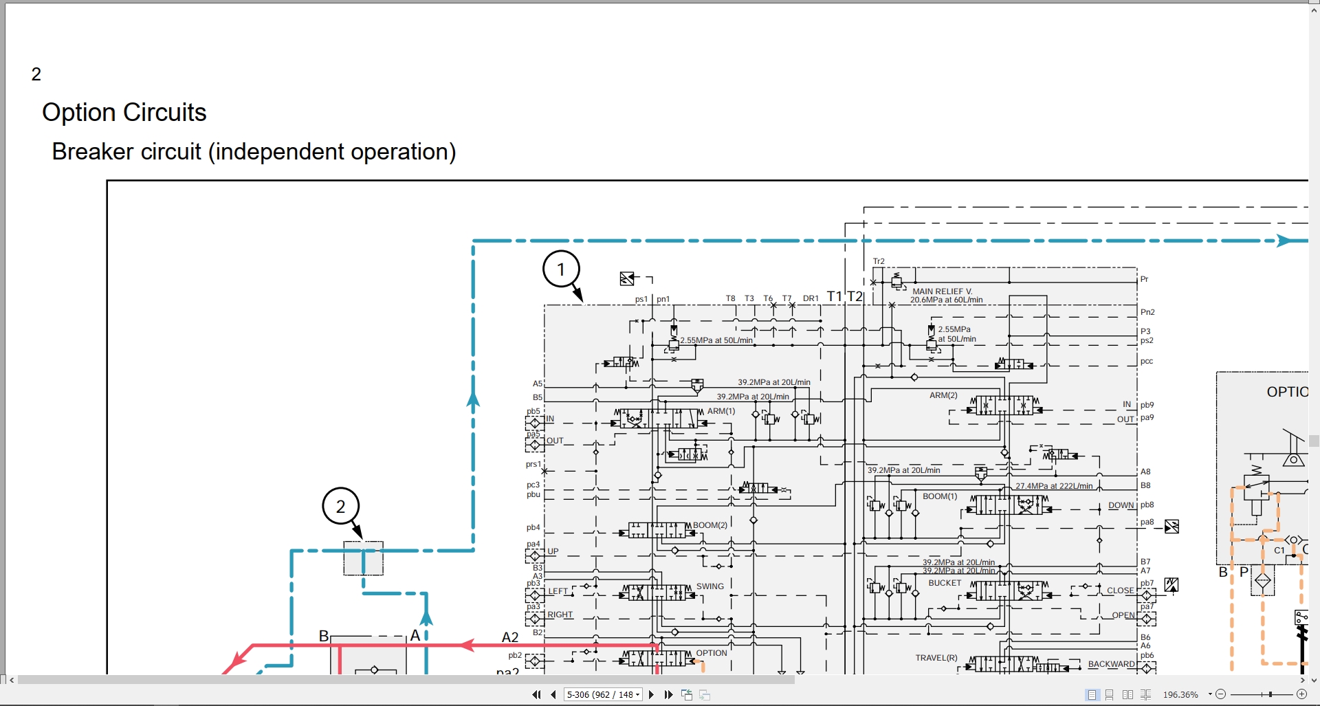
J. Explanation Of Hydraulic Circuit And Operations (Option)
N. Cab
Removal And Installation Of Operator’s Seat
Removal And Installation Of Cab Assembly
Removal And Installation Of Wiper
Removal And Installation Of Cab Front Glass
Removal And Installation Of Right-Side Window Glass
Removal And Installation Of Door (Upper) Sash Glass
Window Lock Adjustment Procedures
Tightening Torque
R. Electrical Parts
Electrical And Engine Functions And Service Support
Basic Functions
Accessories
Battery Disconnect Switch
Reset
Milli-Amp List
Safety
Service Support
Setting
Service Monitor
Computer Explanation
Connection Connector Pin Layout
Sequence Circuit Diagram
Electrical Equipment Layout Diagram
Removal And Installation Of Wiper Controller
Removal And Installation Of Wiper Motor
Removal And Installation Of Monitor
Ecm Replacement Procedure
Removal And Installation Of Ecm
Removal And Installation Of Computer A
Removal And Installation Of Computer B
Air Conditioner Overall Diagram
Assembly And Disassembly Of Unit
Removal And Installation Of Compressor
Removal And Installation Of Condenser
Removal And Installation Of Receiver Dryer
Work Precautions
R. Electrical Connector Wiring Diagram
R. Electrical Parts And Wiring Assembly Diagram
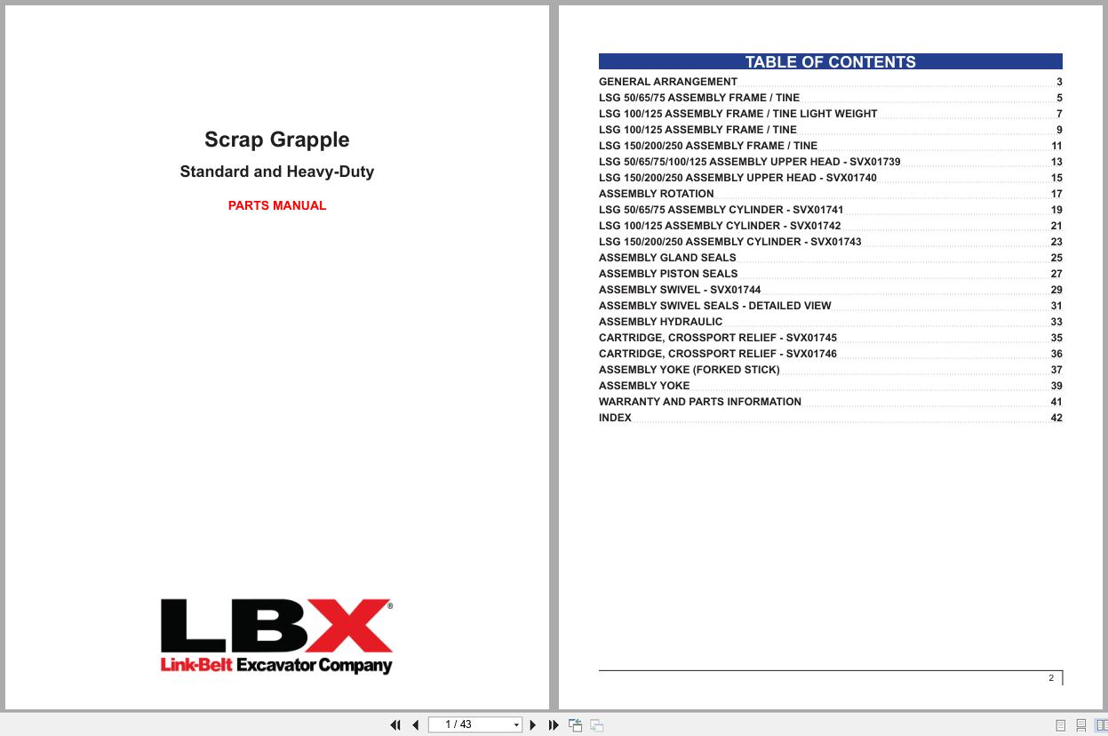
V. Attachments
Main Equipment Table (300×3)
Maintenance Standards
Removal And Installation Of Bucket Cylinder
Removal And Installation Of Arm Cylinder
Removal And Installation Of Boom Cylinder
Procedures For Operation/Assembly And Disassembly Of Hydraulic Cylinder
Port Diagram
Removal And Installation Of Hbcv
Air Bleed Procedure
Removal And Installation Of Bucket
Removal And Installation Of Bucket Link
Removal And Installation Of Arm
Removal And Installation Of Boom
Z. Other
Specifications
Arm Dimension
Main Unit Weight
Bolt Size And Torque Table
Overall View
Work Range Diagram
New Machine Performance Judgment Table
Fluids And Lubricants
Main Unit-Side Diagnostic Trouble Code List
Main Unit-Side Trouble
List Of Special Tools
REALEASE :
REALEASE :

REALEASE :
REALEASE :

REALEASE :
21.09.2021
REALEASE :
21.09.2021
REALEASE :
REALEASE :
REALEASE :
REALEASE :
REALEASE :
REALEASE :
REALEASE :
REALEASE :

REALEASE :
REALEASE :
 Automotive - Heavy Equipment - Truck & Bus - Forklift - Crane