
0 ITEMSVIEW CART


✓
Expert Support
✓
Full Speed
✓
100% Working
Link-Belt Excavator 300X3E Service Manual WLSM3006-00LL-ES 2020 ES
Size: 154.69 MB
Format: PDF
Language: Spanish
Brand: Link-Belt
Type of Machine: Excavator
Type of Manual: Service Manual, Electrical Schematic
Model: Link-Belt 300X3E Excavator
Engine: Isuzu GH-6HK1X Engine
Part Number: WLSM3006-00LL-ES
Publication Date: 2020
Number of Pages: 1664 Pages
50 USD
- Description
Description
Contents:
Seguridad
Seguridad, Información General Y Datos De Par De Apriete Estándar
Información General
Datos De Pares De Apriete Estándar Para Tornillos Y Tuercas
A. Descenso
Tabla De Equipos Principales
Estructura Y TeorÃa De Funcionamiento De Los Equipos Principales
Diagrama De Lumbreras
Funciones Básicas
Retiro E Instalación De La Oruga
Retiro E Instalación Del Rodillo
Retiro E Instalación De La Rueda Dentada Impulsora
Retiro E Instalación Del Rodillo De Recogida
Armado Y Desarmado Del Rodillo De Recogida
Retiro E Instalación Del Cilindro De Engrase
Armado Y Desarmado Del Cilindro De Engrase
Retiro E Instalación De La Junta Central
Armado Y Desarmado De La Junta Central
Retiro E Instalación Del Motor De Propulsión
Armado Y Desarmado Del Motor De Propulsión
Estándares De Mantenimiento
Procedimientos De Medición Y Ajuste De Presión
Procedimientos De Medición Del Volumen De Vaciado
Procedimiento De Purga De Aire
B. C. Unidad De Giro, Contrapeso
Tabla De Equipos Principales
Estructura Y TeorÃa De Funcionamiento De Los Equipos Principales
Diagrama De Lumbreras
Funciones Básicas
Retiro E Instalación De La Unidad De Giro
Armado Y Desarmado Del Motor De Giro
Armado Y Desarmado De La Unidad De Giro
Armado Y Desarmado De La Engranaje Reductor De Giro
Retiro E Instalación Del Contrapeso
Procedimientos De Medición Y Ajuste De Presión
Procedimientos De Medición Del Volumen De Vaciado
Procedimiento De Purga De Aire
H. Motor
Tabla De Equipos Principales
Funciones Básicas
Datos Principales
Función, Estructura Y Funcionamientos
SÃntoma
Inspección De Funcionamiento
Precauciones Durante El Mantenimiento
Retiro E Instalación Del Conjunto De Motor
Retiro E Instalación Del Enfriador De Combustible, Enfriador Del Aire De Carga Del Motor, Radiador Y Enfriador De Aceite
Retiro E Instalación Del Conjunto De Turbocompresor
Inspección Del Filtro De Aire
Retiro E Instalación Del Enfriador De Egr Y De La Válvula De Egr
Retiro E Instalación Del Capó Del Motor
Retiro E Instalación Del Silenciador
Retiro E Instalación De La Cubierta De Culata
Retiro E Instalación Del Piñón Loco
Retiro E Instalación De La Cubierta De Entrada
Retiro E Instalación Del Bloque De Motor
Sistema De Lubricación
Sistema De Enfriamiento
Retiro E Instalación Del Múltiple De Escape
Retiro E Instalación Del Cigüeñal
Retiro E Instalación Del Pistón
Retiro E Instalación Del Ãrbol De Levas
Retiro E Instalación Del Volante
Retiro E Instalación Del Sello De Aceite Delantero Del Cigüeñal
Retiro E Instalación Del Sello De Aceite Trasero Del Cigüeñal
Retiro E Instalación Del Eje De Balancines
Retiro E Instalación Del Resorte De Válvula
Retiro E Instalación Del Sello De Aceite Del Vástago De La Válvula
Retiro E Instalación De La Cubierta Delantera
Retiro E Instalación Del Depósito De Combustible
Retiro E Instalación De La Bomba De Suministro De Combustible
Retiro E Instalación Del Conjunto Del Múltiple De Inyección Común
Retiro E Instalación Del Inyector
Retiro E Instalación Del Filtro De Combustible
Retiro E Instalación De La Válvula De Descarga
Retiro E Instalación Del Filtro De Combustible
Retiro E Instalación Del Arrancador
Retiro E Instalación Del Alternador
Sistema De Precalentamiento
GuÃa Para El Diagnóstico De Problemas
J. Equipos Hidráulicos (Bomba, Válvula Del Sistema De Funcionamiento)
Tabla De Equipos Principales
Funciones Básicas
Diagrama De Lumbreras
Dispositivo Hidráulico
Estructura Y TeorÃa De Funcionamiento De Los Equipos Principales
Válvula De Control
TeorÃa De Funcionamiento De La Válvula De Solenoide De 5 Tubos
Válvula Proporcional De 3 Tubos (Para Piloto)
Electroválvula De 2 Tubos
Válvula Piloto Superior (Válvula De Control Remoto)
Válvula Piloto De Propulsión (Válvula De Control Remoto)
Válvula Piloto Opcional (Válvula De Control Remoto)
Válvula Amortiguadora
Válvula Proporcional De 3 Tubos (Para Piloto)
Operaciones De Purga De Presión
Retiro E Instalación Del Tanque Hidráulico
Retiro E Instalación De La Bomba Hidráulica
Retiro E Instalación Del Acoplamiento De La Bomba
Retiro E Instalación De La Válvula De Control
Retiro E Instalación De Los Bloques Piloto
Retiro E Instalación De La Válvula De Control Remoto De Propulsión
Retiro E Instalación De La Válvula De Control Remoto De Funcionamiento
Retiro E Instalación De La Válvula De Control Remoto Opcional
Retiro E Instalación Del Solenoide De 5 Tubos
Retiro E Instalación De La Válvula Amortiguadora
Procedimientos De Armado Y Desarmado De La Unidad Principal De La Bomba Hidráulica
Estándares De Mantenimiento De La Unidad Principal De La Bomba
Procedimientos De Armado Y Desarmado De La Válvula De Control
Procedimientos De Armado Y Desarmado De La Válvula De Control Remoto De Funcionamiento
Procedimientos De Armado Y Desarmado De La Válvula De Control Remoto Opcional
Procedimientos De Armado Y Desarmado De La Válvula De Control Remoto De Propulsión
Armado Y Desarmado De La Válvula Amortiguadora
Procedimientos De Medición Y Ajuste De Presión
Procedimientos De Medición Del Caudal De La Bomba Hidráulica
Procedimiento De Purga De Aire
Disposición De Equipos Hidráulicos
Vista General
N. Cabina
Retiro E Instalación Del Asiento Del Operador
Retiro E Instalación Del Conjunto De Cabina
Retiro E Instalación Del Limpiaparabrisas
Retiro E Instalación Del Vidrio Delantero De La Cabina
Retiro E Instalación Del Vidrio De La Ventana Del Lado Derecho
Extracción Y Colocación Del Vidrio Del Marco De La Puerta (Superior)
Procedimientos De Ajuste De Bloqueo De La Ventana
Par De Apriete
R. Piezas Eléctricas
Funciones Eléctricas Y Del Motor Y Apoyo De Mantenimiento
Funciones Básicas
Accesorios
Interruptor De Desconexión De BaterÃa
Restauración
Lista De Miliamperios
Seguridad
Service Support
Configuración
Monitor De Servicio
Explicación De La Computadora
Diagrama De Conexión De Las Clavijas De Los Conectores
Diagrama Del Circuito De Secuencia
Diagrama De Disposición De Los Equipos Eléctricos
Retiro E Instalación Del Controlador Del Limpiaparabrisas
Retiro E Instalación Del Motor Del Limpiaparabrisas
Retiro E Instalación Del Monitor
Retiro E Instalación De La Cámara Retrovisora
Retiro E Instalación De La Cámara Lateral (Derecha)
Procedimiento De Sustitución Del Ecm
Retiro E Instalación Del Ecm
Retiro E Instalación De La Computadora A
Retiro E Instalación De La Computadora B
Diagrama General Del Acondicionador De Aire
Armado Y Desarmado De La Unidad
Retiro E Instalación Del Compresor
Retiro E Instalación Del Condensador
Retiro E Instalación Del Secador Acumulador
Precauciones Para Los Procedimientos
V. Accesorios
Tabla De Equipos Principales
Estándares De Mantenimiento
Retiro E Instalación Del Cilindro Del Cucharón
Retiro E Instalación Del Cilindro Del Brazo
Retiro E Instalación Del Cilindro De La Pluma
Procedimientos De Funcionamiento Y Armado/Desarmado Del Cilindro Hidráulico (Realizados Por Kyb)
Diagrama De Lumbreras
Retiro E Instalación De La Hbcv
Procedimiento De Purga De Aire
Retiro E Instalación Del Cucharón
Retiro E Instalación Del Varillaje Del Cucharón
Retiro E Instalación Del Brazo
Retiro E Instalación De La Pluma
Z. Otros
Especificaciones
Dimensión Del Brazo
Peso De La Unidad Principal
Tabla De Tamaños Y Pares De Apriete De Pernos
Vista General
Diagrama De Rango De Funcionamiento
Tabla De Valoración De Rendimiento De La Máquina Nueva
Fluidos Y Lubricantes
Lista De Códigos De Diagnóstico De Problemas En El Lateral De La Unidad Principal
Problema En El Lateral De La Unidad Principal
Lista De Herramientas Especiales
Contents:
Security
Safety, General Information and Standard Torque Data
General Information
Standard Tightening Torque Data for Screws and Nuts
A. Descent
Main Equipment Table
Structure and Theory of Operation of Main Equipment
Louvre Diagram
Basic Functions
Track Removal and Installation
Roller Removal and Installation
Drive Sprocket Removal and Installation
Pickup Roller Removal and Installation
Assembling and Disassembling the Pickup Roller
Grease Cylinder Removal and Installation
Assembly and Disassembly of the Grease Cylinder
Removal and Installation of the Central Board
Assembly and Disassembly of the Central Board
Propulsion Motor Removal and Installation
Assembling and Disassembling the Propulsion Motor
Maintenance Standards
Pressure Measurement and Adjustment Procedures
Void Volume Measurement Procedures
Air Purge Procedure
B. C. Swing Unit, Counterweight
Main Equipment Table
Structure and Theory of Operation of Main Equipment
Louvre Diagram
Basic Functions
Removal and Installation of the Swing Unit
Assembling and Disassembling the Swing Motor
Assembling and Disassembling the Turning Unit
Assembling and Disassembling the Swing Reduction Gear
Counterweight Removal and Installation
Pressure Measurement and Adjustment Procedures
Void Volume Measurement Procedures
Air Purge Procedure
H. Engine
Main Equipment Table
Basic Functions
Main Data
Function, Structure and Operations
Symptom
Operation Inspection
Precautions During Maintenance
Engine Assembly Removal and Installation
Removal and Installation of Fuel Cooler, Engine Charge Air Cooler, Radiator and Oil Cooler
Turbocharger Assembly Removal and Installation
Air Filter Inspection
Egr Cooler And Egr Valve Removal And Installation
Engine Hood Removal and Installation
Muffler Removal and Installation
Cylinder Head Cover Removal and Installation
Idler Pinion Removal And Installation
Entry Cover Removal and Installation
Engine Block Removal and Installation
Lubrication System
Cooling System
Exhaust Manifold Removal And Installation
Crankshaft Removal And Installation
Piston Removal And Installation
Camshaft Removal and Installation
Steering Wheel Removal and Installation
Crankshaft Front Oil Seal Removal And Installation
Crankshaft Rear Oil Seal Removal And Installation
Rocker Shaft Removal and Installation
Valve Spring Removal and Installation
Valve Stem Oil Seal Removal and Installation
Front Cover Removal and Installation
Fuel Tank Removal and Installation
Removal and Installation of the Fuel Supply Pump
Removal and Installation of the Common Injection Manifold Assembly
Injector Removal and Installation
Fuel Filter Removal and Installation
Discharge Valve Removal and Installation
Fuel Filter Removal and Installation
Starter Removal and Installation
Alternator Removal and Installation
Preheating System
Guide to Diagnosing Problems
J. Hydraulic Equipment (Pump, Valve Operating System)
Main Equipment Table
Basic Functions
Louvre Diagram
Hydraulic Device
Structure and Theory of Operation of Main Equipment
Control valve
5 Pipe Solenoid Valve Working Theory
3-Pipe Proportional Valve (For Pilot)
2-Pipe Solenoid Valve
Upper Pilot Valve (Remote Control Valve)
Propulsion Pilot Valve (Remote Control Valve)
Optional Pilot Valve (Remote Control Valve)
Damper Valve
3-Pipe Proportional Valve (For Pilot)
Pressure Bleed Operations
Removal and Installation of the Hydraulic Tank
Removal and Installation of the Hydraulic Pump
Pump Coupling Removal and Installation
Control Valve Removal and Installation
Removal and Installation of Pilot Blocks
Propulsion Remote Control Valve Removal and Installation
Removal and Installation of Remote Operating Control Valve
Removal and Installation of Optional Remote Control Valve
5 Pipe Solenoid Removal And Installation
Damper Valve Removal and Installation
Procedures for Assembling and Disassembling the Main Unit of the Hydraulic Pump
Pump Main Unit Maintenance Standards
Control Valve Assembly and Disassembly Procedures
Operating Remote Control Valve Assembly and Disassembly Procedures
Optional Remote Control Valve Assembly and Disassembly Procedures
Assembly and Disassembly Procedures Propulsion Remote Control Valve
Assembling and Disassembling the Damper Valve
Pressure Measurement and Adjustment Procedures
Hydraulic Pump Flow Measurement Procedures
Air Purge Procedure
Hydraulic Equipment Arrangement
Overview
N. Cabin
Operator Seat Removal and Installation
Cabin Assembly Removal and Installation
Windshield Wiper Removal and Installation
Cabin Front Glass Removal and Installation
Removal and Installation of Right Side Window Glass
Removing and Replacing the Door Frame Glass (Upper)
Window Lock Adjustment Procedures
Tightening Torque
R. Electrical Parts
Electrical and Engine Functions and Maintenance Support
Basic Functions
Accessories
Battery Disconnect Switch
Restoration
Milliampere List
Security
Service Support
Configuration
Service Monitor
Computer Explained
Connector Pin Connection Diagram
Sequence Circuit Diagram
Electrical Equipment Arrangement Diagram
Wiper Controller Removal and Installation
Windshield Wiper Motor Removal And Installation
Monitor Removal and Installation
Rearview Camera Removal and Installation
Side Camera Removal and Installation (Right)
Ecm Replacement Procedure
Ecm Removal And Installation
Removal and Installation of Computer A
Removal and Installation of Computer B
General Diagram Of The Air Conditioner
Assembling and Disassembling the Unit
Compressor Removal and Installation
Condenser Removal and Installation
Accumulator Dryer Removal and Installation
Precautions for Procedures
V. Accessories
Main Equipment Table
Maintenance Standards
Bucket Cylinder Removal And Installation
Arm Cylinder Removal and Installation
Boom Cylinder Removal and Installation
Operating Procedures and Assembly/Disassembly of the Hydraulic Cylinder (Performed by Kyb)
Louvre Diagram
Removal and Installation of the Hbcv
Air Purge Procedure
Bucket Removal And Installation
Bucket Linkage Removal And Installation
Arm Removal and Installation
Boom Removal and Installation
Z. Others
Specs
Arm Dimension
Main Unit Weight
Bolt Size and Tightening Torque Chart
Overview
Operating Range Diagram
New Machine Performance Rating Table
Fluids and Lubricants
List of Diagnostic Trouble Codes on the Side of the Main Unit
Problem On The Side Of The Main Unit
List of Special Tools
Related Products
-
Link-Belt Wheel Loader L120 Service Manual Electrical Schematic
40 USDSize: 98.22 MBFormat: PDFLanguage: EnglishBrand: Link-BeltType of Machine: Wheel LoaderType of Manual: Service Manual, Electrical SchematicModel: Link-Belt L120 Wheel LoaderEngine: Cummins 4BTA3.9 EngineList of Files:L120 Service Manual 1122.pdf (660 Pages)L120WL L125WL Electrical Schematic.pdf (37 Pages)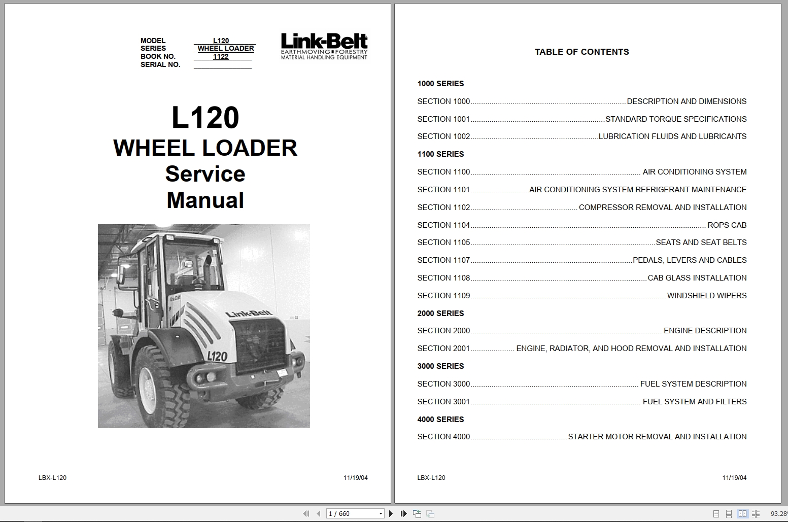
REALEASE :
REALEASE :
-
Link-Belt Shear Shield LXS Field Installation Manual
10 USDSize: 4.56 MBFormat: PDFLanguage: EnglishBrand: Link-BeltType of Machine: Shear ShieldType of Manual: Field Installation ManualModel: Link-Belt Shear Shield LXSNumber of Pages: 24 Pages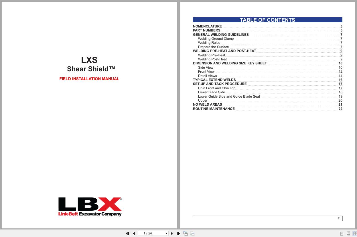
REALEASE :
REALEASE :
-
Linkbelt Excavator, Wheel Loader, Articulated Truck 8.9 GB DVD Shop Manual, Part Manual, Schematic Diagram
Original price was: 200.140Current price is: 140. USDLinkbelt Excavator, Wheel Loader, Articulated Truck 8.9 GB DVD Shop Manual, Part Manual, Schematic DiagramSize: 8.9 GbLanguage: EnglishBrand: LinkbeltType of machine: Linkbelt Excavator, Wheel Loader, Articulated TruckFormat: PDF, IMGType: Shop Manual, Part Manual, Electrical Schematic, Hydraulic SchematicWindow: All Window 32 & 64 bitAmount of DVD: 1 DVD rarHigh-speed Link DownloadHot-30%
REALEASE :
21.09.2021
REALEASE :
21.09.2021
-
Link-Belt Rubber Tiered Material Handler 360X2 Shop Manual
30 USDSize: 39.00 MBFormat: PDFLanguage: EnglishBrand: Link-BeltType of Machine: Material HandlerType of Manual: Shop Manual, Hydraulic And Electrical SchematicModel: Link-Belt 360X2 Material HandlerEngine: Isuzu 6HK1XYSS Diesel EngineNumber of Pages: 755 Pages
REALEASE :
REALEASE :
-
Link-Belt Wheel Loader L130 Service Manual Electrical Schematic
40 USDSize: 87.01 MBFormat: PDFLanguage: EnglishBrand: Link-BeltType of Machine: Wheel LoaderType of Manual: Service Manual, Electrical SchematicModel: Link-Belt L130 Wheel LoaderEngine: Cummins 6BTA5.9 EngineList of Files:L130 Service Manual 1121.pdf (652 Pages)L130 WL Electrical Schematic.pdf (35 Pages)
REALEASE :
REALEASE :
-
Link-Belt Scrap Grapple Standard and Heavy-Duty Parts Manual
15 USDSize: 7.09 MBFormat: PDFLanguage: EnglishBrand: Link-BeltType of Machine: Scrap Grapple Standard and Heavy-DutyType of Manual: Parts ManualModel: Link-Belt Scrap Grapple Standard and Heavy-DutyNumber of Pages: 43 Pages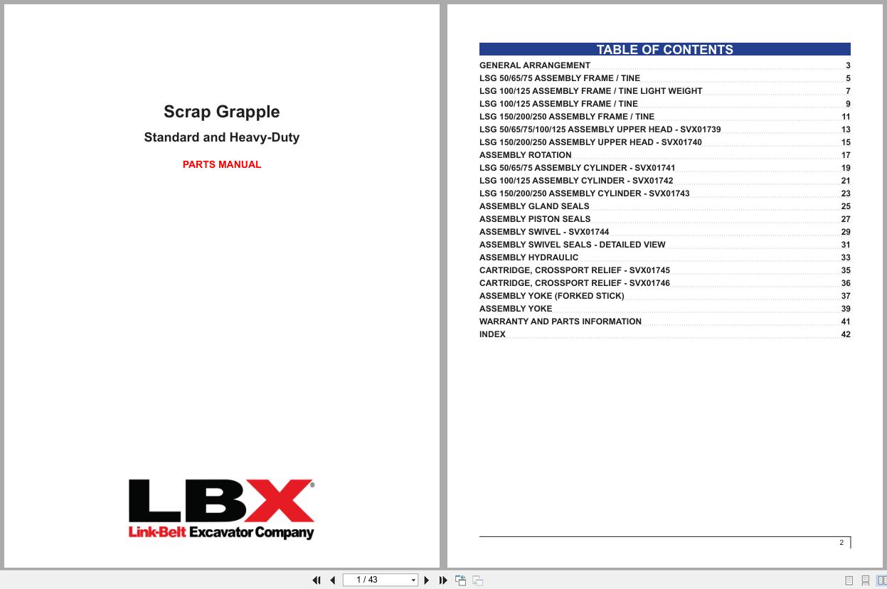
REALEASE :
REALEASE :
-
Link-Belt Wheel Loader L125 Service Manual Electrical Schematic
40 USDSize: 97.03 MBFormat: PDFLanguage: EnglishBrand: Link-BeltType of Machine: Wheel LoaderType of Manual: Service Manual, Electrical SchematicModel: Link-Belt L125 Wheel LoaderEngine: Cummins 6BTA5.9 EngineList of Files:L120WL L125WL Electrical Schematic.pdf (37 Pages)L125 Service Manual 1123.pdf (656 Pages)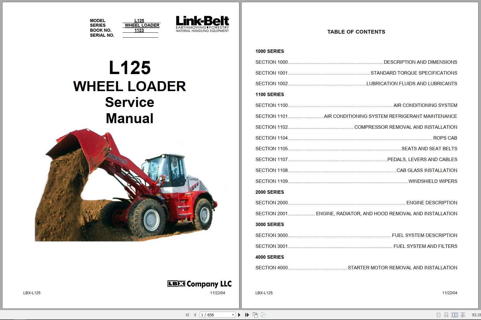
REALEASE :
REALEASE :
-
Link-Belt Scrap Grapple LSG All Models Safety Operator Manual
15 USDSize: 12.77 MBFormat: PDFLanguage: EnglishBrand: Link-BeltType of Machine: Scrap GrappleType of Manual: Safety And Operator ManualModel: Link-Belt Scrap Grapple LSG All ModelsNumber of Pages: 49 Pages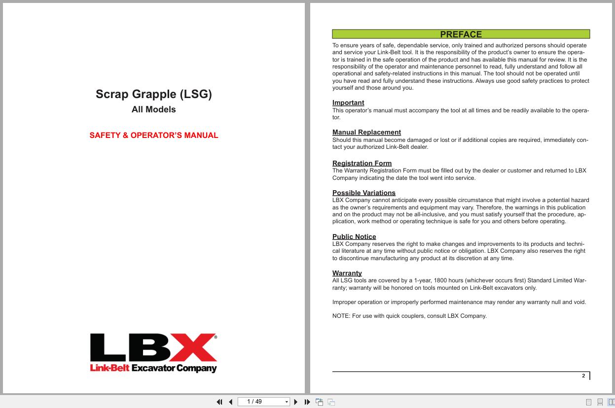
REALEASE :
REALEASE :