

Expert Support
Full Speed
100% Working
Mercedes Benz E63S AMG Brakes, Traction Control, Engine Repair Manuals and Wiring Diagrams
Original price was: 70.50Current price is: 50. USD
- Description
Description
Contents:
Repair Manual – Brakes and Traction Control – Apply brake paste to brake caliper and brake caliper support.pdf
Repair Manual – Brakes and Traction Control – Bleed brake system.pdf
Repair Manual – Brakes and Traction Control – Brake system inspect fluid level.pdf
Repair Manual – Brakes and Traction Control – Carrying out bleeding operation.pdf
Repair Manual – Brakes and Traction Control – Connect disconnect testing unit at brake booster.pdf
Repair Manual – Brakes and Traction Control – Detach mount connector.pdf
Repair Manual – Brakes and Traction Control – Flare brake line.pdf
Repair Manual – Brakes and Traction Control – Remove install brake booster vacuum line.pdf
Repair Manual – Brakes and Traction Control – Remove install brake booster.pdf
Repair Manual – Brakes and Traction Control – Remove install brake lines.pdf
Repair Manual – Brakes and Traction Control – Remove install electric parking brake actuator motor.pdf
Repair Manual – Brakes and Traction Control – Remove install electric parking brake switch.pdf
Repair Manual – Brakes and Traction Control – Remove install ETS ASR ESP(R) hydraulic unit.pdf
Repair Manual – Brakes and Traction Control – Remove Install Front Axle Brake Caliper [AR42.10P0070LW].pdf
Repair Manual – Brakes and Traction Control – Remove Install Front Axle Brake Caliper [AR42.10P0070LWB].pdf
Repair Manual – Brakes and Traction Control – Remove Install Front Axle Brake Caliper [AR42.10P0070LWC].pdf
Repair Manual – Brakes and Traction Control – Remove Install Front Axle Brake Caliper [AR42.10P0070LWD].pdf
Repair Manual – Brakes and Traction Control – Remove install front axle brake caliper.pdf
Repair Manual – Brakes and Traction Control – Remove install left front or right rpm sensor.pdf
Repair Manual – Brakes and Traction Control – Remove install left or right rear axle speed sensor.pdf
Repair Manual – Brakes and Traction Control – Remove install master brake cylinder.pdf
Repair Manual – Brakes and Traction Control – Remove install park pawl capacitor.pdf
Repair Manual – Brakes and Traction Control – Remove install pedal assembly.pdf
Repair Manual – Brakes and Traction Control – Remove install PRESAFE(R) Pulse radar sensor in front bumper.pdf
Repair Manual – Brakes and Traction Control – Remove Install RearAxle Brake Caliper [AR42.10P0080LW].pdf
Repair Manual – Brakes and Traction Control – Remove install short and longrange radar sensor.pdf
Repair Manual – Brakes and Traction Control – Remove install vacuum pump.pdf
Repair Manual – Brakes and Traction Control – Removing and installing brake fluid reservoir.pdf
Repair Manual – Brakes and Traction Control – Replace brake fluid.pdf
Repair Manual – Brakes and Traction Control – Replace brake hoses.pdf
Repair Manual – Brakes and Traction Control – Service Information Brake caliper with MercedesBenz brand cover.pdf
Repair Manual – Cooling – Check lowtemperature circuit coolant level.pdf
Repair Manual – Cooling – Check main circuit coolant level.pdf
Repair Manual – Cooling – Drain fill lowtemperature circuit coolant.pdf
Repair Manual – Cooling – Drain pour in coolant.pdf
Repair Manual – Cooling – Open close coupling.pdf
Repair Manual – Cooling – Open, close coolant line coupling.pdf
Repair Manual – Cooling – Remove and install heat exchanger.pdf
Repair Manual – Cooling – Remove and install multifunction sensor.pdf
Repair Manual – Cooling – Remove install additional cooler for engine in right wheel arch.pdf
Repair Manual – Cooling – Remove install additional engine radiator.pdf
Repair Manual – Cooling – Remove install circulation pumps for lowtemperature circuit.pdf
Repair Manual – Cooling – Remove install coolant circuit feed line of turbochargers.pdf
Repair Manual – Cooling – Remove install coolant circuit return line of turbochargers.pdf
Repair Manual – Cooling – Remove install coolant circuit vent line of right turbocharger.pdf
Repair Manual – Cooling – Remove install coolant pump.pdf
Repair Manual – Cooling – Remove install coolant temperature sensor.pdf
Repair Manual – Cooling – Remove install coolant thermostat heating element.pdf
Repair Manual – Cooling – Remove install coolant thermostat.pdf
Repair Manual – Cooling – Remove install expansion reservoir.pdf
Repair Manual – Cooling – Remove install fan unit.pdf
Repair Manual – Cooling – Remove install lower radiator shutters.pdf
Repair Manual – Cooling – Remove install lowtemperature circuit additional radiator.pdf
Repair Manual – Cooling – Remove install radiator.pdf
Repair Manual – Cooling – Remove install shutoff valve.pdf
Repair Manual – Cooling – Remove install upper radiator shutters.pdf
Repair Manual – Cooling – Replace lowtemperature circuit coolant.pdf
Repair Manual – Cooling – Replace main circuit coolant.pdf
Repair Manual – Engine – Assign crankshaft bearing shells.pdf
Repair Manual – Engine – Assign piston to the cylinder bore.pdf
Repair Manual – Engine – Basic function of engine oil pressure and temperature sensor.pdf
Repair Manual – Engine – Check crankshaft in removed state.pdf
Repair Manual – Engine – Check engine oil level using onboard oil dipstick.pdf
Repair Manual – Engine – Check engine oil level with instrument cluster.pdf
Repair Manual – Engine – Connect disconnect compression pressure test equipment.pdf
Repair Manual – Engine – Detach attach holder for camshafts.pdf
Repair Manual – Engine – Detach attach special tool for fixing camshaft in place.pdf
Repair Manual – Engine – Determine crankshaft bearing axial play.pdf
Repair Manual – Engine – Engine oil and oil filter change.pdf
Repair Manual – Engine – Firing order.pdf
Repair Manual – Engine – Measure piston ring end gap.pdf
Repair Manual – Engine – Measure vertical clearance of piston rings.pdf
Repair Manual – Engine – Mount connecting rod bearing.pdf
Repair Manual – Engine – Notes on assessing wear on connecting rod bearings and connecting rod journals.pdf
Repair Manual – Engine – Notes on the assessment of pistons and piston rings.pdf
Repair Manual – Engine – Oil pan bottom section tightening procedure.pdf
Repair Manual – Engine – Pry off oil pan.pdf
Repair Manual – Engine – Reduce fuel pressure through service valve.pdf
Repair Manual – Engine – Relieve fuel pressure.pdf
Repair Manual – Engine – Remove corrosion from crankshaft.pdf
Repair Manual – Engine – Remove install belt pulley vibration damper.pdf
Repair Manual – Engine – Remove install bottom part of oil pan.pdf
Repair Manual – Engine – Remove install camshafts of left cylinder bank.pdf
Repair Manual – Engine – Remove install camshafts of right cylinder bank.pdf
Repair Manual – Engine – Remove install crankshaft.pdf
Repair Manual – Engine – Remove install engine cover.pdf
Repair Manual – Engine – Remove install engine mount acceleration sensor.pdf
Repair Manual – Engine – Remove install engine oil cooler.pdf
Repair Manual – Engine – Remove install engine oil fill level sensor.pdf
Repair Manual – Engine – Remove install filler neck for engine oil.pdf
Repair Manual – Engine – Remove install front cover on left cylinder head.pdf
Repair Manual – Engine – Remove install front cover on right cylinder head.pdf
Repair Manual – Engine – Remove install front engine mount.pdf
Repair Manual – Engine – Remove install guide pulley for polyV belt of alternator.pdf
Repair Manual – Engine – Remove install guide pulley for refrigerant compressor polyVbelt.pdf
Repair Manual – Engine – Remove install heat exchanger.pdf
Repair Manual – Engine – Remove install hydraulic valve clearance compensating elements.pdf
Repair Manual – Engine – Remove install left charge air distributor.pdf
Repair Manual – Engine – Remove install left cylinder head.pdf
Repair Manual – Engine – Remove install left front engine support.pdf
Repair Manual – Engine – Remove install left secondary chain drive chain tensioner.pdf
Repair Manual – Engine – Remove install lift solenoid of left exhaust camshaft at front.pdf
Repair Manual – Engine – Remove install lift solenoid of left exhaust camshaft at rear.pdf
Repair Manual – Engine – Remove install lift solenoid of left intake camshaft at front.pdf
Repair Manual – Engine – Remove install lift solenoid of left intake camshaft at rear.pdf
Repair Manual – Engine – Remove install lift solenoid of right exhaust camshaft at front.pdf
Repair Manual – Engine – Remove install lift solenoid of right exhaust camshaft at rear.pdf
Repair Manual – Engine – Remove install lift solenoid of right intake camshaft at front.pdf
Repair Manual – Engine – Remove install lift solenoid of right intake camshaft at rear.pdf
Repair Manual – Engine – Remove install oil circuit feed line of turbochargers.pdf
Repair Manual – Engine – Remove install oil circuit return line of left turbocharger.pdf
Repair Manual – Engine – Remove install oil circuit return line of right turbocharger.pdf
Repair Manual – Engine – Remove install oil pan.pdf
Repair Manual – Engine – Remove install oil pressure control valve on oil pump.pdf
Repair Manual – Engine – Remove install piston rings.pdf
Repair Manual – Engine – Remove install piston.pdf
Repair Manual – Engine – Remove install poly Vbelt of alternator.pdf
Repair Manual – Engine – Remove install primary chain drive chain tensioner.pdf
Repair Manual – Engine – Remove install primary chain drive timing chain.pdf
Repair Manual – Engine – Remove install rear engine mount.pdf
Repair Manual – Engine – Remove install rear engine support.pdf
Repair Manual – Engine – Remove install refrigerant compressor polyVbelt.pdf
Repair Manual – Engine – Remove install right charge air distributor.pdf
Repair Manual – Engine – Remove install right cylinder head.pdf
Repair Manual – Engine – Remove install right front engine support.pdf
Repair Manual – Engine – Remove install right rear engine suspension lug.pdf
Repair Manual – Engine – Remove install right secondary chain drive chain tensioner.pdf
Repair Manual – Engine – Remove install secondary chain drive timing chains.pdf
Repair Manual – Engine – Remove install solenoids of camshafts in left cylinder head.pdf
Repair Manual – Engine – Remove install solenoids of camshafts in right cylinder head.pdf
Repair Manual – Engine – Remove install tensioning device for polyV belt of alternator.pdf
Repair Manual – Engine – Remove install tensioning device for polyV belt of refrigerant compressor.pdf
Repair Manual – Engine – Remove install valve springs.pdf
Repair Manual – Engine – Remove install valves.pdf
Repair Manual – Engine – Replace air filter element.pdf
Repair Manual – Engine – Replace front radial shaft sealing ring.pdf
Repair Manual – Engine – Replace fuel filter.pdf
Repair Manual – Engine – Replace rear radial shaft sealing ring.pdf
Repair Manual – Engine – Replace spark plugs.pdf
Repair Manual – Engine – Replace valve stem seals .pdf
Repair Manual – Engine – Replace valve stem seals.pdf
Repair Manual – Engine – Service Information Cleaning of carbonized intake valves.pdf
Repair Manual – Engine – Service Information Engine cover.pdf
Repair Manual – Engine – Service Information Oil specification for engine oil changes.pdf
Repair Manual – Engine – Service Information Spark plug connector grease.pdf
Repair Manual – Engine – Set basic position of camshafts.pdf
Repair Manual – Engine – Tighten connecting rod bolts.pdf
Repair Manual – Engine – Tightening procedure for crankshaft bearing caps.pdf
Repair Manual – Engine – Tightening procedure for cylinder head bolts.pdf
Repair Manual – Exhaust – Exhaust system temperature sensor, basic function.pdf
Repair Manual – Exhaust – Remove install catalytic converters.pdf
Repair Manual – Exhaust – Remove install exhaust manifold heat shield.pdf
Repair Manual – Exhaust – Remove install left exhaust manifold.pdf
Repair Manual – Exhaust – Remove install left rear muffler.pdf
Repair Manual – Exhaust – Remove install right exhaust manifold.pdf
Repair Manual – Exhaust – Remove install right rear muffler.pdf
Repair Manual – Exhaust – Temperature sensor upstream of exhaust gas turbocharger, basic function.pdf
Wiring Diagams – Brakes and Traction Control – Abbreviations of signal and circuit designations for wiring diagrams.pdf
Wiring Diagams – Brakes and Traction Control – Use of wiring diagrams.pdf
Wiring Diagams – Brakes and Traction Control – Wiring diagram brake wear indicator.pdf
Wiring Diagams – Cooling System – Wiring diagram for coolant level switch.pdf
Wiring Diagams – Emission Control – Electrical function schematic for exhaust treatment.pdf
Wiring Diagams – Emission Control – Use of electrical function schematics.pdf
Wiring Diagams – Power Managment – Abbreviations of signal and circuit designations for wiring diagrams.pdf
Wiring Diagams – Power Managment – Electrical function diagram for ignition OFF.pdf
Wiring Diagams – Power Managment – Electrical function diagram for injection control.pdf
Wiring Diagams – Power Managment – Electrical function schematic for camshaft adjustment.pdf
Wiring Diagams – Power Managment – Electrical function schematic for charging.pdf
Wiring Diagams – Power Managment – Electrical function schematic for cylinder shutoff.pdf
Wiring Diagams – Power Managment – Electrical function schematic for deceleration fuel shutoff.pdf
Wiring Diagams – Power Managment – Electrical function schematic for engine limphome mode.pdf
Wiring Diagams – Power Managment – Electrical function schematic for engine management, ECO start stop function.pdf
Wiring Diagams – Power Managment – Electrical function schematic for exhaust treatment.pdf
Wiring Diagams – Power Managment – Electrical function schematic for fuel supply.pdf
Wiring Diagams – Power Managment – Electrical function schematic for ignition system.pdf
Wiring Diagams – Power Managment – Electrical function schematic for knock control.pdf
Wiring Diagams – Power Managment – Electrical function schematic for lambda control.pdf
Wiring Diagams – Power Managment – Electrical function schematic for rpm control.pdf
Wiring Diagams – Power Managment – Electrical function schematic for safety fuel shutoff.pdf
Wiring Diagams – Power Managment – Electrical function schematic for smooth running control.pdf
Wiring Diagams – Power Managment – Electrical function schematic for start phase, poststart phase and warmup enrichment.pdf
Wiring Diagams – Power Managment – Electrical function schematic for starting.pdf
Wiring Diagams – Power Managment – Electrical function schematic for thermal management.pdf
Wiring Diagams – Power Managment – Electrical function schematic for torque coordination.pdf
Wiring Diagams – Power Managment – Electrical function schematic, alternator interface.pdf
Wiring Diagams – Power Managment – Electrical function schematic, ignition ON.pdf
Wiring Diagams – Power Managment – Electrical function schematic, synchronization of the injection and firing order.pdf
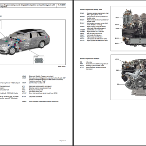
Wiring Diagams – Power Managment – Overview of system components for gasoline injection and ignition system with direct injection.pdf
Wiring Diagams – Power Managment – Wiring diagram for drive unit control unit.pdf
Wiring Diagams – Power Managment – Wiring diagram for drivetrain control unit [PE54.21P214197DDB].pdf
Wiring Diagams – Power Managment – Wiring diagram for drivetrain control unit.pdf
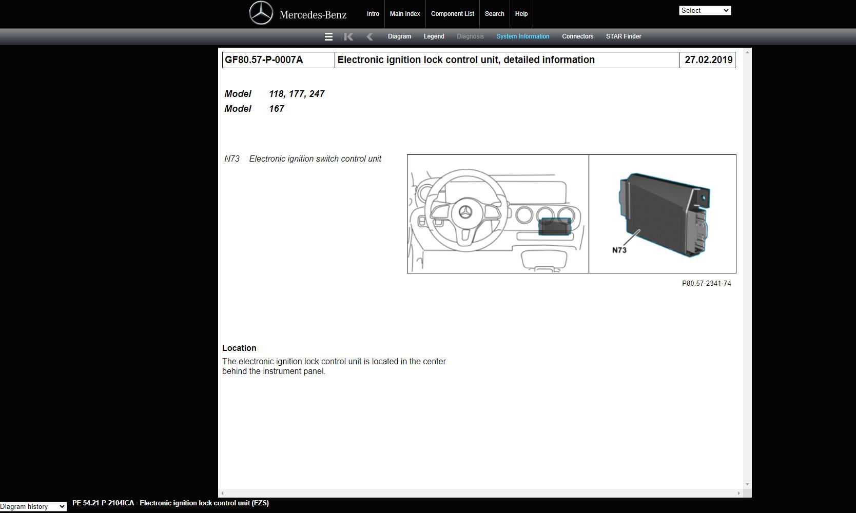
Wiring Diagams – Power Managment – Wiring diagram for electronic ignition lock control unit (EZS) [PE54.21P210497DBA].pdf
Wiring Diagams – Power Managment – Wiring diagram for electronic ignition lock control unit (EZS) [PE54.21P210497DDA].pdf
Wiring Diagams – Power Managment – Wiring diagram for gasoline direct injection system control unit [PE07.08P210197DBE].pdf
Wiring Diagams – Power Managment – Wiring Diagram for Gasoline Direct Injection System Control Unit [PE07.08P2101DBF].pdf
Wiring Diagams – Power Managment – Wiring Diagram for Gasoline Direct Injection System Control Unit [PE07.08P2101DDC].pdf
Wiring Diagams – Power Managment – Wiring Diagram for Gasoline Direct Injection System Control Unit [PE07.08P2101DDD].pdf
Related Products
-
Mercedes-Benz Full Set Manual DVD
Original price was: 33.20Current price is: 20. USD -
Mercedes-Benz Engine Truck Service Repair Manual Wiring Diagram DVD
Original price was: 50.20Current price is: 20. USD -
Mercedes Truck All Models Full Manuals DVD
Original price was: 100.45Current price is: 45. USD -
Mercedes Benz Truck Sprinter 3500XD Crew (907.653) V6-3.0L DSL Turbo (642.899) Diagrams Electrical, Service and Repair Manual 2020
Original price was: 200.100Current price is: 100. USD -
Mercedes Benz GLC350e 2020 Electrical Wiring Diagrams
50 USD -
Mercedes Benz Component Location Starfinder WEB ETM 2023
Original price was: 150.75Current price is: 75. USD -
Mercedes Benz 3.99GB Old Model Collection Manuals PDF
Original price was: 50.25Current price is: 25. USD -
Mercedes Computer Based Training – Global Technical Training Information DVD
Original price was: 200.50Current price is: 50. USD