Expert Support
Full Speed
100% Working
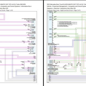
Mercedes Benz GLA250 2022 4MATIC Electrical Wiring Diagrams
Original price was: 70.50Current price is: 50. USD
- Description
Description
Contents:
Air Conditioning – Automatic AC Circuit (Heating and Air Conditioning).pdf
Anti-Lock Brakes (Antilock Brakes Traction Control Systems).pdf
Body Computer (Body Control Module).pdf
Computer Data Lines – Data Link Connector Circuit (Information Bus).pdf
Computer Data Lines – HighLow Bus Circuit (Information Bus).pdf
Cooling Fans (Radiator Cooling Fan).pdf
Cruise Control (Cruise Control).pdf
Defogger (Rear Defogger).pdf
Electronic Power Steering – Electronic Power Steering Circuit (Power Steering).pdf
Electronic Power Steering – Power Steering Column Circuit (Power Steering).pdf
Electronic Suspension (Suspension Control ( Automatic – Electronic )).pdf
Engine Controls (Powertrain Management).pdf
Exterior Lights – Backup Lamps Circuit (Lighting and Horns).pdf
Exterior Lights – Exterior Lamps Circuit (W LED Headlamps) (Lighting and Horns).pdf
Exterior Lights – Exterior Lamps Circuit (WO LED Headlamps) (Lighting and Horns).pdf
Exterior Lights – Trailer Light Circuit (Lighting and Horns).pdf
Ground Distribution (Power and Ground Distribution).pdf
Headlights – W Dynamic LED Headlamps (Headlamp).pdf
Headlights – W Static LED Headlamps (Headlamp).pdf
Headlights – WO LED Headlamps (Headlamp).pdf
Heated Steering Wheel Circuit (Steering Wheel).pdf
Horns (Horn).pdf
Instrument Cluster – Collision Avoidance Circuit (Instrument Panel, Gauges and Warning Indicators).pdf
Instrument Cluster – Instrument Cluster Circuit (Instrument Panel, Gauges and Warning Indicators).pdf
Instrument Cluster – Overhead Console Circuit (Instrument Panel, Gauges and Warning Indicators).pdf
Interior Lights – Courtesy Lamps Circuit (Lighting and Horns).pdf
Interior Lights – Instrument Illumination Circuit (Lighting and Horns).pdf
Memory Systems – Driver’s Memory Seat Circuit (Memory Positioning Systems).pdf
Memory Systems – Memory Mirrors Circuit (Memory Positioning Systems).pdf
Memory Systems – Passenger’s Memory Seat Circuit (Memory Positioning Systems).pdf
Mirrors (Mirrors).pdf
Navigation – Augmented Reality Camera Circuit (Navigation System).pdf
Navigation – Blind Spot Information System Circuit (Navigation System).pdf
Navigation – COMAND Actuation Circuit (Navigation System).pdf
Navigation – Multifunction Camera Circuit (Navigation System).pdf
Navigation – Parktronic Circuit (Navigation System).pdf
Navigation – Rear Camera Circuit (Navigation System).pdf
Power Distribution (Power and Ground Distribution).pdf
Seats – Front Multicontour Seat Circuit (Seats).pdf
Seats – Front Ventilation & Heated Seat Circuit (W Memory) (Seats).pdf
Seats – Front Ventilation & Heated Seat Circuit (WO Memory) (Seats).pdf
Seats – Lumbar Circuit (Seats).pdf
Shift Interlock (Transmission and Drivetrain).pdf
Sound Systems – COMAND Actuation Circuit (Radio, Stereo, and Compact Disc).pdf
Sound Systems – Sound Amplifier Circuit (Radio, Stereo, and Compact Disc).pdf
Starting Charging – Charging Circuit (Starting and Charging).pdf
Starting Charging – Starting Circuit (Starting and Charging).pdf
Transmissions – AT Circuit (Transmission and Drivetrain).pdf
Transmissions – AWD Circuit (Transmission and Drivetrain).pdf
Trunk, Tailgate, Fuel Doors – Trunk Pull-Down Circuit (Doors, Hood and Trunk).pdf
Warning Systems – Seat Belt Warning Circuit (Instrument Panel, Gauges and Warning Indicators).pdf
Warning Systems – Tire Pressure Monitoring Circuit (Instrument Panel, Gauges and Warning Indicators).pdf
WiperWasher (Wiper and Washer Systems).pdf
Connectors – Body Computer – Front SAM Control Module Circuit (Body Control Module).pdf
Connectors – Location of electrical connectors – Center console.pdf
Connectors – Location of electrical connectors – Engine compartment.pdf
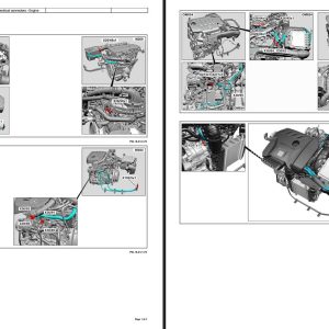
Connectors – Location of electrical connectors – Engine.pdf
Connectors – Location of electrical connectors – Front bumper.pdf
Connectors – Location of electrical connectors – Instrument panel.pdf
Connectors – Location of electrical connectors – Left front door.pdf
Connectors – Location of electrical connectors – Left front wheel well.pdf
Connectors – Location of electrical connectors – Left rear door.pdf
Connectors – Location of electrical connectors – Left vehicle interior.pdf
Connectors – Location of electrical connectors – Rear bench seatrear seats.pdf
Connectors – Location of electrical connectors – Rear bumper.pdf
Connectors – Location of electrical connectors – Rear end.pdf
Connectors – Location of electrical connectors – Right front door.pdf
Connectors – Location of electrical connectors – Right front wheel well.pdf
Connectors – Location of electrical connectors – Right rear door.pdf
Connectors – Location of electrical connectors – Right vehicle interior.pdf
Connectors – Location of electrical connectors – Roof.pdf
Connectors – Location of electrical connectors – Trunk lidtailgate.pdf
Connectors – Location of electrical connectors – Trunkload compartment.pdf
Connectors – Location of electrical connectors – Underbody.pdf
Related Products
-
Mercedes Benz GLC350e 2020 Electrical Wiring Diagrams
50 USD -
Mercedes Truck All Models Full Manuals DVD
Original price was: 100.45Current price is: 45. USD -
Mercedes-Benz Engine Truck Service Repair Manual Wiring Diagram DVD
Original price was: 50.20Current price is: 20. USD -
Mercedes Benz 3.99GB Old Model Collection Manuals PDF
Original price was: 50.25Current price is: 25. USD -
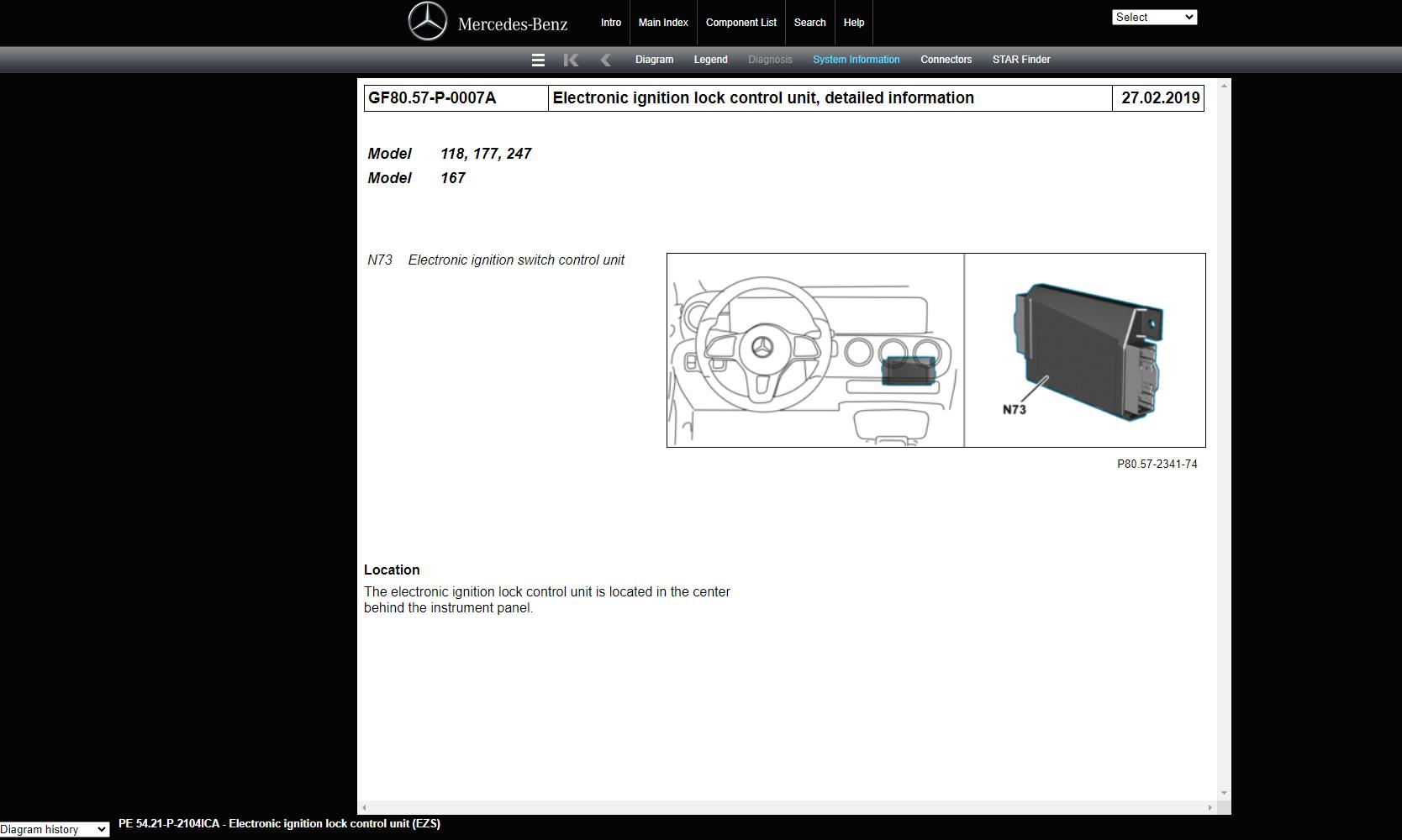
Mercedes Benz Component Location Starfinder WEB ETM 2023
Original price was: 150.75Current price is: 75. USD -
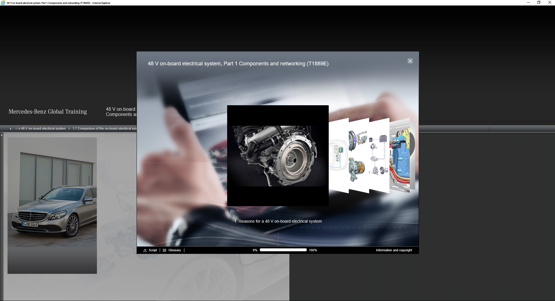
Mercedes Computer Based Training – Global Technical Training Information DVD
Original price was: 200.50Current price is: 50. USD -
Mercedes-Benz Full Set Manual DVD
Original price was: 33.20Current price is: 20. USD -
Mercedes Benz Truck Sprinter 3500XD Crew (907.653) V6-3.0L DSL Turbo (642.899) Diagrams Electrical, Service and Repair Manual 2020
Original price was: 200.100Current price is: 100. USD