
0 ITEMSVIEW CART


✓
Expert Support
✓
Full Speed
✓
100% Working
New Holland Excavator E80MSR Workshop Manual 60413421
Size: 53.60 MB
Format: PDF
Language: English
Brand: New Holland
Type of Machine: Excavator
Type of Manual: Workshop Manual, Electrical Schematic, Hydraulic Schematic
Model: New Holland E80MSR Excavator
Part Number: 60413421
Number of Pages: 940 Pages
30 USD
- Description
Description
Contents:
1. Outline
1.1 General Precautions For Repairs
1.2 International Unit Conversion System (Based On Marks’ Standard Handbook For Mechanical Engineers)
2. Specifications
2.1 Name Of Components
2.2 Machine Dimensions
2.3 Weight Of Components
2.4 Transportation Dimension And Weight
2.5 Specifications And Performance
2.6 Type Of Crawler
2.7 Type Of Bucket
2.8 Combinations Of Attachment
2.9 Engine Specification
3. Attachment Dimensions
3.1 Boom
3.2 Arm
3.3 Bucket
3.4 Dozer
3.5 Swing
11. Tools
11.1 Torque Specifications For Capscrews & Nuts
11.2 Screw And Tool Sizes
11.3 Torque Specifications For Joints And Hoses
11.4 Torque Specifications For Sleeve Type Tube Fittings
11.5 Plugs
11.6 Special Spanners For Tubes
11.7 Special Tools
11.8 Application Of Screw Locking And Sealing Compounds
11.9 Suction Stopper
11.10 Counterweight Lifting Jig
11.11 Upper Frame Lifting Jig
11.12 Engine Mounting Pedestal
11.13 Track Spring Set Jig
12. Standard Maintenance Time Schedule
12.1 Standard Maintenance Time Schedule For Excavator
12.2 Standard Working Time Table For The Maintenance Of Engine
13. Maintenance Standard And Test Procedure
13.1 How To Use Maintenance Standard And Precautions
13.2 Performance Inspection Standard Table
13.3 Measurement Of Engine Speed
13.4 Measurement Of Hydraulic Pressure
13.5 Measuring Travel Performances
13.6 Measuring Slewing Performances
13.7 Measuring Attachment Operating Performances
13.8 Measuring Performances Of Slewing Bearing
13.9 Mechatro Controller “A” Adjustment
21. Mechatro Control System
21.1 Summary Of Mechatro Control System
21.2 Boom Raise Conflux Mechatro Control System
21.3 Slewing Cut Valve Control Mechatro Control System
21.4 Arm In / Out Conflux Mechatro Control System
21.5 Travel Straight Mechatro Control System
21.6 Travel Boost Control System
21.7 Mechatro Control
22. Hydraulic System
22.1 Summary
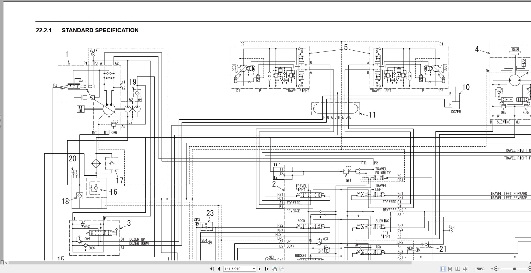
22.2 Hydraulic Circuits And Component Models
22.3 Neutral Circuit
22.4 Travel Circuit
22.5 Bucket Circuit
22.6 Boom Circuit
22.7 Slewing Circuit
22.8 Arm Circuit
22.9 Boom Swing Circuit
22.10 Nibbler & Breaker Circuit
22.11 Combined Circuit (Multiple Circuit)
22.12 Dozer Circuit
22.13 Travel And Dozer Circuit
22.14 Control Lines
22.15 Upper & Lower Hyd. Lines
22.16 Att Hyd. Lines
23. Electrical System
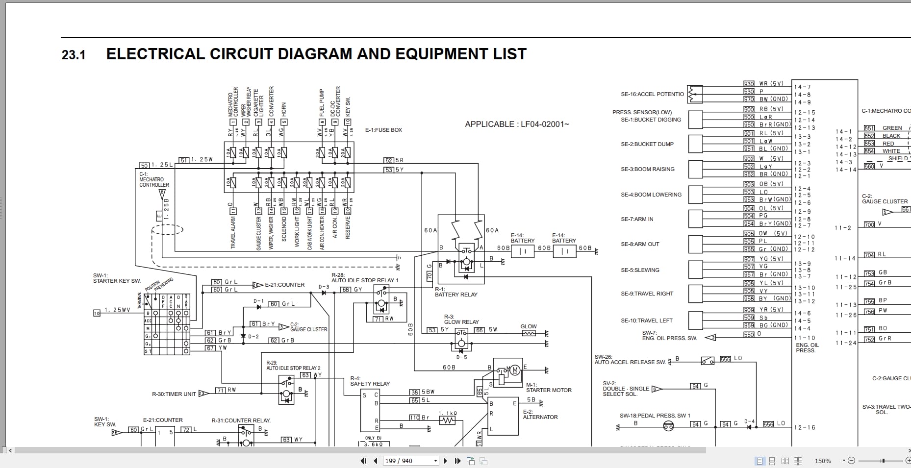
23.1 Electrical Circuit Diagram And Equipment List
23.2 Harness
24. Components System
24.1 Hydraulic Components
24.2 Electric Equipment
25. Air-Conditioner System
25.1 Construction And Piping
25.2 Construction Of Main Components
25.3 Function
25.4 Disassembly And Assembly
25.5 Charging Refrigerant
25.6 Electric Circuit
25.7 Troubleshooting
31. General Disassembly And Assembly
31.1 General Disassembly And Assembly
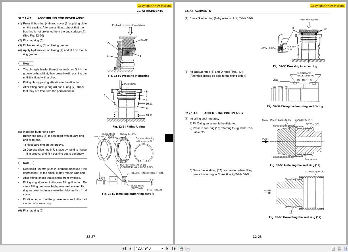
32. Attachments
32.1 Removing And Installing
32.2 Disassembling And Assembling
33. Upper Slewing Body
33.1 Removing And Installing
33.2 Disassembling And Assembling
34. Travel System
34.1 Removing And Installing
34.2 Disassembling And Assembling
41. Troubleshooting (Mechatro Control)
41.1 Outline
41.2 Table Of Actuator For Troubleshooting : Mechatro Control
41.3 Troubleshooting Summarized : Mechatro Control
41.4 Check Point For Mechatro System
42. Troubleshooting (Hydraulic System)
42.1 Trouble Diagnosis : Hydraulic
42.2 Troubleshooting
43. Troubleshooting (Electric)
43.1 Trouble Diagnosis Table : Electric
43.2 Controller Error Code Display
43.3 Service Diagnosis
44. Troubleshooting (Engine)
44.1 Trouble Diagnosis : Engine
44.2 Troubleshooting
51. Engine
Related Products
-
New Holland Construction Service Manual 3.9GB PDF DVD Updated [11.2020]
Original price was: 300.250Current price is: 250. USDNew Holland Construction Service Manual 3.9GB PDF DVD Updated [11.2020]Size: 3.9 GB PackTotal: 84 ManualsLanguage: EnglishBrand: New HollandType of machine: New Holland ConstructionType of document: Service ManualNew Model updated 01.2019-11.2020Windows: All Window 32 & 64bitFormat Document: pdfAmount of DVD: 1 DVDHigh speed link downloadHot-17%
REALEASE :
17.11.2020
REALEASE :
17.11.2020
-
New Holland Construction Equipment Excavator Service Manuals DVD
Original price was: 178.120Current price is: 120. USDNew Holland Construction Equipment Excavator Service Manuals DVDSize: 5.72GbLanguage: EnglishBrand: New HollandType of Machine: Construction Equipment ExcavatorType of Document: Service ManualWindows: All Window 32 & 64bitFormat Document: pdfHigh Speed Link DownloadAmount of DVD: 1 DVDJust download and use no need installNote: Read clear descryption and contents firstHot-33%
REALEASE :
08.06.2019
REALEASE :
08.06.2019
-
New Holland AG AGRICULTURE Updated 04.2020 170GB Service Manual PDF
Original price was: 1,000.340Current price is: 340. USDNew Holland AG AGRICULTURE Service Manual PDF Updated 04.2020 170GBSize: 170GbLanguage: EnglishBrand: New Holland AGRICULTUREType of machine: New Holland NAFTA AGRICULTUREType of document: Service ManualNew Model updatedWindows: All Window 32 & 64bitFormat document: pdfAmount of DVD: 1 DVDTotal file: 1750 file pdf only Service ManualUpdated [04.2020]High Speed Link DownloadHot-66%
REALEASE :
04.05.2020
REALEASE :
04.05.2020
-
New Holland Construction Equipment Telehandlers Service Manuals
Original price was: 122.100Current price is: 100. USDNew Holland Construction Equipment Telehandlers Service ManualsSize: 3.3GbLanguage: EnglishBrand: New HollandType of Machine: Construction Equipment TelehandlersType of Document: Service ManualWindows: All Window 32 & 64bitFormat Document: pdfHigh Speed Link DownloadJust download and use no need installNote: Read clear descryption and contents firstHot-18%
REALEASE :
08.06.2019
REALEASE :
08.06.2019
-
New Holland AG Agricultural Tractor 2022 PDF Service Manual
USDNew Holland AG Agricultural Tractor 2022 PDF Service ManualLanguage: English, German, Multi-Language…Brand: Kobelco Heavy EquipmentType of machine: Kobelco Heavy Equipment MachineryType of document: Service ManualWindows: All Windows 32 & 64bit, MAC OSFormat document: PDF1. You can see some models clear in this list2. If you need to exchange so contact us3. If you need one model so contact usWrite us detail here: We have full all modelItem Number:…………………….Description:…………………….Language:…………………….Type:…………………….Model:…………………….CONTACT US FOR PAYMENT:Skype: AutoepcserviceWhatsapp: https://wa.me/message/LXJU2U6GMOV4E1Email: admin@autoepcservice.com or autoepcservice@gmail.comWorking Days/Hours: [Mon-Sat]/[8:00AM-20:00PM]WeChat ID: AUTOEPCSERVICEFanpage: https://www.facebook.com/Autoepcsoftware/REALEASE :
13.04.2022
-
New Holland Construction Equipment Dozer Service Manuals
Original price was: 122.100Current price is: 100. USDNew Holland Construction Equipment Dozer Service ManualsSize: 1.89GbLanguage: EnglishBrand: New HollandType of Machine: Construction Equipment DozerType of Document: Service ManualWindows: All Window 32 & 64bitFormat Document: pdfHigh Speed Link DownloadJust download and use no need installNote: Read clear descryption and contents firstHot-18%
REALEASE :
08.06.2019
REALEASE :
08.06.2019
-
New Holland CE Construction 2022 PDF Service Manual
USDNew Holland CE Construction 2022 PDF Service ManualLanguage: English, German, Multi-Language…Brand: Kobelco Heavy EquipmentType of machine: Kobelco Heavy Equipment MachineryType of document: Service ManualWindows: All Windows 32 & 64bit, MAC OSFormat document: PDF1. You can see some models clear in this list2. If you need to exchange so contact us3. If you need one model so contact usWrite us detail here: We have full all modelItem Number:…………………….Description:…………………….Language:…………………….Type:…………………….Model:…………………….CONTACT US FOR PAYMENT:Skype: AutoepcserviceWhatsapp: https://wa.me/message/LXJU2U6GMOV4E1Email: admin@autoepcservice.com or autoepcservice@gmail.comWorking Days/Hours: [Mon-Sat]/[8:00AM-20:00PM]WeChat ID: AUTOEPCSERVICEFanpage: https://www.facebook.com/Autoepcsoftware/REALEASE :
13.04.2022
-
New Holland Construction Equipment Backhoe Loader Service Manuals
Original price was: 110.100Current price is: 100. USDNew Holland Construction Equipment Backhoe Loader Service ManualsSize: 3.04GbLanguage: EnglishBrand: New HollandType of Machine: Construction Equipment Backhoe LoaderType of Document: Service ManualWindows: All Window 32 & 64bitFormat Document: pdfHigh Speed Link DownloadAmount of DVD: 1 DVDJust download and use no need installNote: Read clear descryption and contents firstHot-9%
REALEASE :
08.06.2019
REALEASE :
08.06.2019

