
9 ITEMSVIEW CART


Total: 525.00
Expert Support
Full Speed
100% Working
30 USD
Contents:
Section 01 – Safety Precautions
1 General Safety Instructions
2 Use Instruction
Section 02 – Controls And Instruments
1 Switches And Push-Buttons
2 Controls And Pedals
3 Multi-Function Display
Section 03 – Technical Specifications
1 Main Components
2 Dimensions – Operating Weights
3 Digging Performance
4 Lifting Capacities
5 Hydraulic System
6 Rotation
7 Travel
71 Tyres
8 Brakes
9 Steering
10 Electrical System
11 Buckets
12 Tightening Torques
13 Centralized Lubrication Pump (Optional)
14 Fuel System
15 Engine
16 Supply Summarizing Chart
Section 04 – Upper Structure
1 Main Components
2 Slewing Bearing
3 Rotation Gearmotor
31 Disassembly And Assembly
4 Multi-Cooler
41 Technical Specifications
5 Hydraulic Pumps
6 Muffler
7 Hydraulic Oil Tank
8 Air Filter
9 Counterweight
10 Fuel System
11 Cab And Operator’s Seat
111 Cab At Variable Height (Mh 66 Industry – Mh 86 Industry)
12 Centralized Lubrication Pump
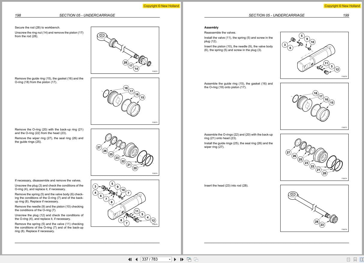
Section 05 – Undercarriage
1 Undercarriage Components
2 Rear Rigid Axle
21 Technical Specifications
22 Disassembly And Assembly
23 Disassembly And Assembly
24 Troubleshooting
25 Special Tools
3 Travel Motor
31 Technical Specifications
32 Disassembly And Assembly
33 Disassembly And Assembly
4 Cardan Shaft
41 Disassembly And Assembly
5 Front Steering Axle
51 Technical Specifications
52 Disassembly And Assembly
53 Disassembly And Assembly
54 Troubleshooting
55 Special Tools
6 Wheels And Tyres
7 Blade
71 Blade Cylinder
8 Axle Floating Locking Cylinders
81 Technical Specifications
82 Disassembly And Assembly
83 Air Bleeding
84 Disassembly And Assembly
85 Troubleshooting
9 Stabilizers
91 Stabilizer Cylinders
92 Troubleshooting
10 Left Ladder
11 Right Ladder And Tool Storage Box
12 Rotary Control Valve And Electric Rotor
121 Technical Specifications
122 Disassembly And Assembly
123 Disassembly And Assembly
124 Electric Rotor
Section 06 – Front Attachment
1 Types Of Front Attachment
2 Hydraulic Cylinders
21 Boom Cylinder
22 Dipper Cylinder (Mh 66 – Mh 86)
23 Dipper Cylinder (Mh 66 Industry – Mh 86 Industry)
24 Special Tools
3 Buckets Mh 66 – Mh 86
4 Mh 66 – Mh 86 Quick Coupler
5 Clamshell Bucket
Section 07 – Steering System
1 Operation
2 Power Steering
21 Disassembly And Assembly
3 Priority Valve
4 Troubleshooting
Section 08 – Brake System
1 Operation
2 Service Brake
3 Parking Brake
4 Pedal Brake Valve
5 Accumulators
6 Troubleshooting
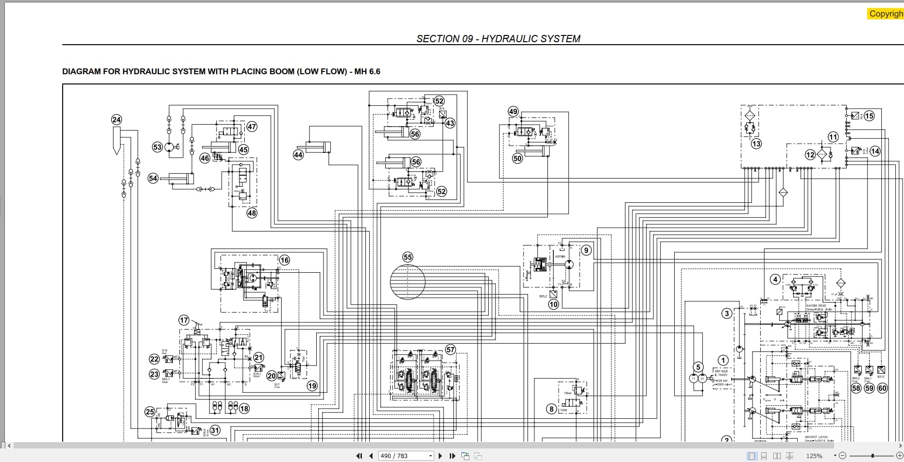
Section 09 – Hydraulic System
1 Hydraulic System
2 Hydraulic System Diagrams
21 Hydraulic System Diagrams – Upper Structure
22 Hydraulic System Diagrams – Undercarriage
23 Hydraulic System Diagrams Blade And/Or Stabilizers
3 Hydraulic Pumps
4 Upper Structure Control Valve
5 Undercarriage Control Valve
6 Pilot Control Assy
7 Rotation System
8 Travel
9 Stabilization Hydraulic System
10 Boom Hydraulic System
11 Hydraulic System
12 Hydraulic System Of Dipper
13 Hydraulic System Of Placing Boom
14 Hydraulic System With Combination Of Different Functions
(Boom, Placing Boom, Dipper And Bucket)
15 Hydraulic System Of Hammer (With Placing Boom)
16 Hydraulic System Of Hammer And Shears (With Placing Boom)
17 Hydraulic System Of Shears (With Placing Boom)
18 Hydraulic System Of Hammer (With Monoboom)
19 Hydraulic System Of Hammer And Shears (With Monoboom)
20 Hydraulic System Of Shears (With Monoboom)
21 Troubleshooting
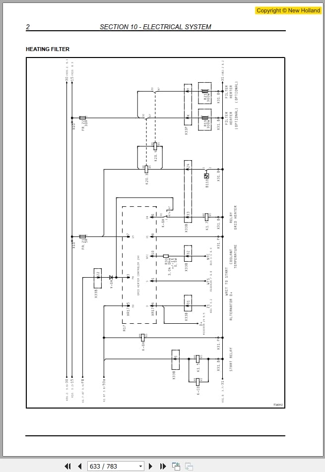
Section 10 – Electrical System
1 Electrical Diagrams
11 Mh 66 – Mh 86
12 Mh 66 Industry – Mh 86 Industry
2 Fuses
3 Batteries
4 Bulbs
5 Troubleshooting
Section 11 – Electronics
1 Main Components
11 Electrical Power Supply Diagram
2 Components Of Line 1
3 Components Of Line 2
31 Travel Pedal
32 Attachment Pedal (Placing Boom And Hammer)
33 Electro-Hydraulic System
34 Power Control System
4 Engine Speed Actuator
5 Coolant Temperature Detection
6 Charge Air Temperature Detection
7 Hydraulic Oil Temperature Detection
8 Proportional Valve – Fan Motor
9 Proportional Valves – Control Block
Section 12 – Calibration
1 Necessary Operations Before Calibration
2 Display: Calibration Menu
3 Calibrations With The Engine Running
31 Vdo Calibration
32 Power Calibration
33 Main Valve Calibration (Control Valve)
34 Travel Calibration
35 Pump Delivery Calibration
36 Rotation Pump Calibration
37 Auxiliary Pressure Calibration
4 Calibrations With The Engine Stopped
41 Calibrations, All Solenoid Valves, Main Pump, Rotation Pump,
Auxiliary Pressure
42 Main Valve Calibration (Control Valve)

REALEASE :
17.11.2020
REALEASE :
17.11.2020

REALEASE :
08.06.2019
REALEASE :
08.06.2019

REALEASE :
08.06.2019
REALEASE :
08.06.2019
REALEASE :
13.04.2022

REALEASE :
04.05.2020
REALEASE :
04.05.2020
REALEASE :
13.04.2022

REALEASE :
08.06.2019
REALEASE :
08.06.2019

REALEASE :
08.06.2019
REALEASE :
08.06.2019
 Automotive - Heavy Equipment - Truck & Bus - Forklift - Crane
