
2 ITEMSVIEW CART


Total: 195.00

Expert Support
Full Speed
100% Working
30 USD
Contents:
Section 01 – Safety Precautions
1. Introduction
1.1 Designated Use
2. General Safety Instructions
3. Use Instruction
3.1 Level Of Vibrations Transmitted To The Operator
3.2 Noise Levels
3.3 Travelling On Public Roads
Section 02 – Controls And Instruments
1. Switches And Push-Buttons
2. Controls And Pedals
3. Multi-Function Display
Section 03 – Technical Specifications
1. Main Components
1.1 2-Piece Boom Attachment (We190)
1.2 2-Piece Boom Attachment (We210 – We230)
1.3 Monoboom Attachment (We190 – We210 – We230)
1.4 Handling Attachment (We210 Industrial – We230 Industrial)
2. Dimensions – Operating Weights
2.1 We190 Models
2.2 We210 Models
2.3 We230 Models
2.4 We210 Industrial Models
2.5 We230 Industrial Models
3. Digging Performance
3.1 We190 Models
3.2 We210 Models
3.3 We230 Models
3.4 We210 Industrial Models
3.5 We230 Industrial Models
4. Lifting Capacities
4.1 We190 Models
4.2 We210 Models
4.3 We230 Models
4.4 We210 Industrial Models
4.5 We230 Industrial Models
5. Hydraulic System
5.1 Pumps
6. Slewing
6.1 Slewing Gearbox
7. Travel
7.1 Tyres
8. Brakes
9. Steering
10. Electrical System
11. Buckets
11.1 Buckets – We190
11.2 Buckets – We210
11.3 Buckets – We230
12. Tightening Torques
13. Fuel System
14. Engine
15. Supply Summarizing Chart
Section 04 – Upper Structure
1. Main Components
2. Slewing Bearing
3. Slewing Gearbox
3.1 Technical Specifications
3.2 Removal And Installation
3.3 Disassembly And Assembly
3.4 Special Tools
3.5 Troubleshooting
4. Multi-Cooler
4.1 Technical Specifications
4.2 Removal And Installation Expansion Tank
4.3 Coolant Level, Top-Up And Change
4.4 Removal And Installation Of Fan And Hydraulic Motor
5. Hydraulic Pumps
6. Muffler
7. Hydraulic Oil Tank
7.1 Oil Return Filter
7.2 Level Check And Top-Up
7.3 Oil Change And Cleaning
7.4 Bleeding Valve
8. Air Filter
9. Counterweight
9.1 Counterweight Disassembly
10. Fuel System
10.1 Fuel Tank
10.2 Fuel Filters
11. Cab And Operator’s Seat
11.1 Cab Assembly
11.2 Cab At Variable Height (We210 Industrial – We230 Industrial)
12. Centralized Lubrication
12.1 Safety Instructions
12.2 Operation
12.3 Maintenance
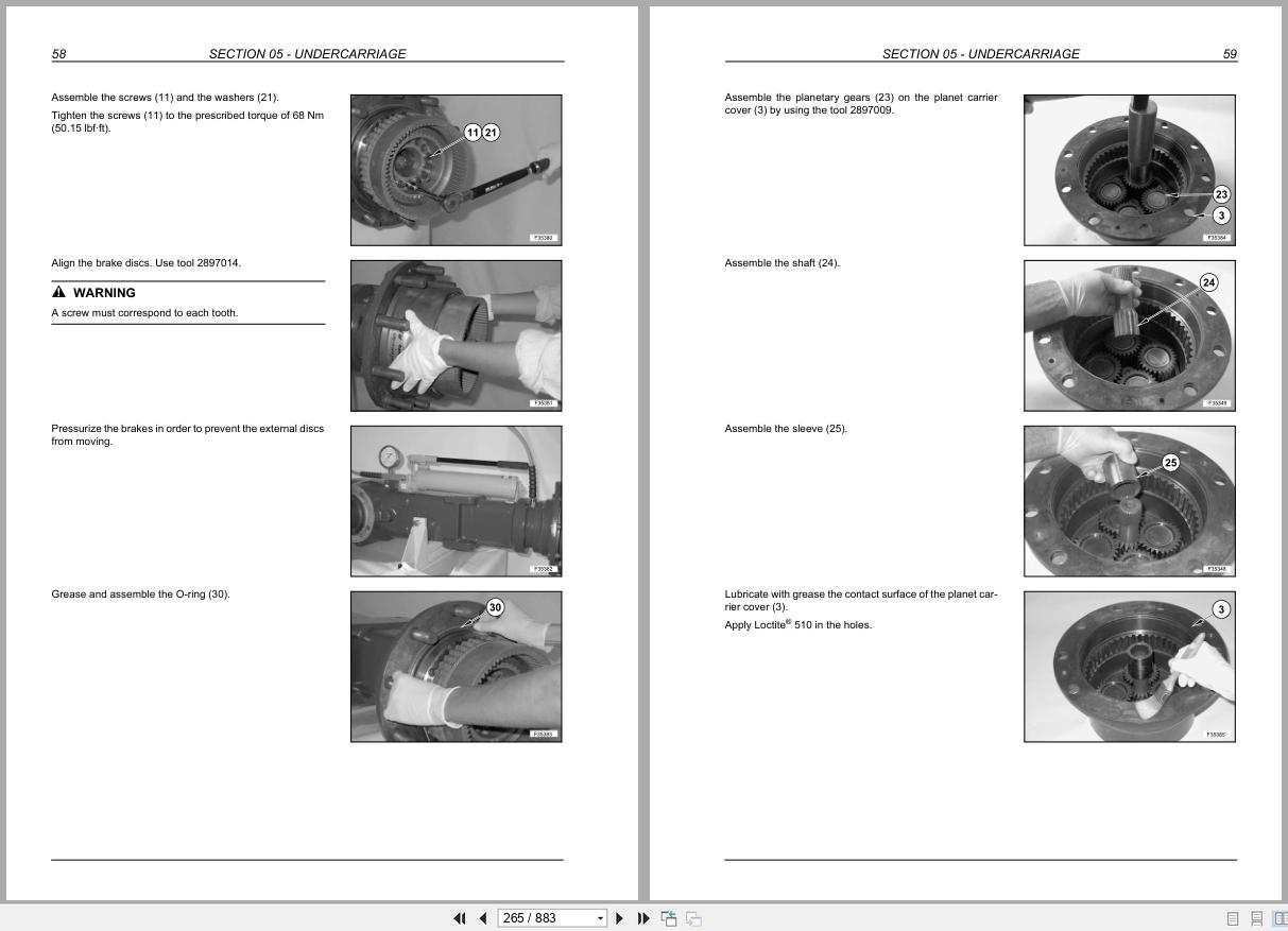
Section 05 – Undercarriage
1. Undercarriage Components
2. Rear Rigid Axle
2.1 Technical Specifications
2.2 Disassembly
2.3 Disassembly And Assembly
2.4 Troubleshooting
2.5 Special Tools
3. Travel Motor
3.1 Technical Specifications
3.2 Disassembly And Assembly
3.3 Disassembly And Assembly
4. Cardan Shaft
4.1 Disassembly And Assembly
5. Front Steering Axle
5.1 Technical Specifications
5.2 Disassembly And Assembly
5.3 Disassembly And Assembly
5.4 Troubleshooting
5.5 Special Tools
6. Wheels And Tyres
6.1 Tyres
7. Blade
7.1 Blade Cylinder
8. Axle Floating Locking Cylinders
8.1 Technical Specifications
8.2 Disassembly And Assembly
8.3 Air Bleeding
8.4 Disassembly And Assembly
8.5 Troubleshooting
9. Stabilizers
9.1 Stabilizer Cylinders
9.2 Troubleshooting
10. Left Ladder
11. Right Ladder And Tool Storage Box
12. Rotary Control Valve And Electric Rotor
12.1 Technical Specifications
12.2 Disassembly And Assembly
12.3 Rotary Control Valve Overall
12.4 Electric Rotor
Section 06 – Front Attachment
1. Types Of Front Attachment
2. Hydraulic Cylinders
2.1 Boom Cylinder
2.2 Dipper Cylinder (We190 – We210 – We230)
2.3 Dipper Cylinder (We210 Industrial – We230 Industrial)
2.4 Bucket Cylinder
2.5 Boom Adjusting Cylinder
2.6 Special Tools
3. Buckets
3.1 Buckets – We190
3.2 Buckets – We210
3.3 Buckets – We230
3.4 Bucket Teeth – Change
Section 07 – Steering System
4. Operation
5. Power Steering
5.1 Technical Specifications
5.2 Operation
5.3 Disassembly And Assembly
6. Priority Valve
7. Troubleshooting
Section 08 – Brake System
1. Operation
2. Service Brake
3. Parking Brake
4. Pedal Brake Valve
5. Accumulators
5.1 Maintenance
6. Troubleshooting
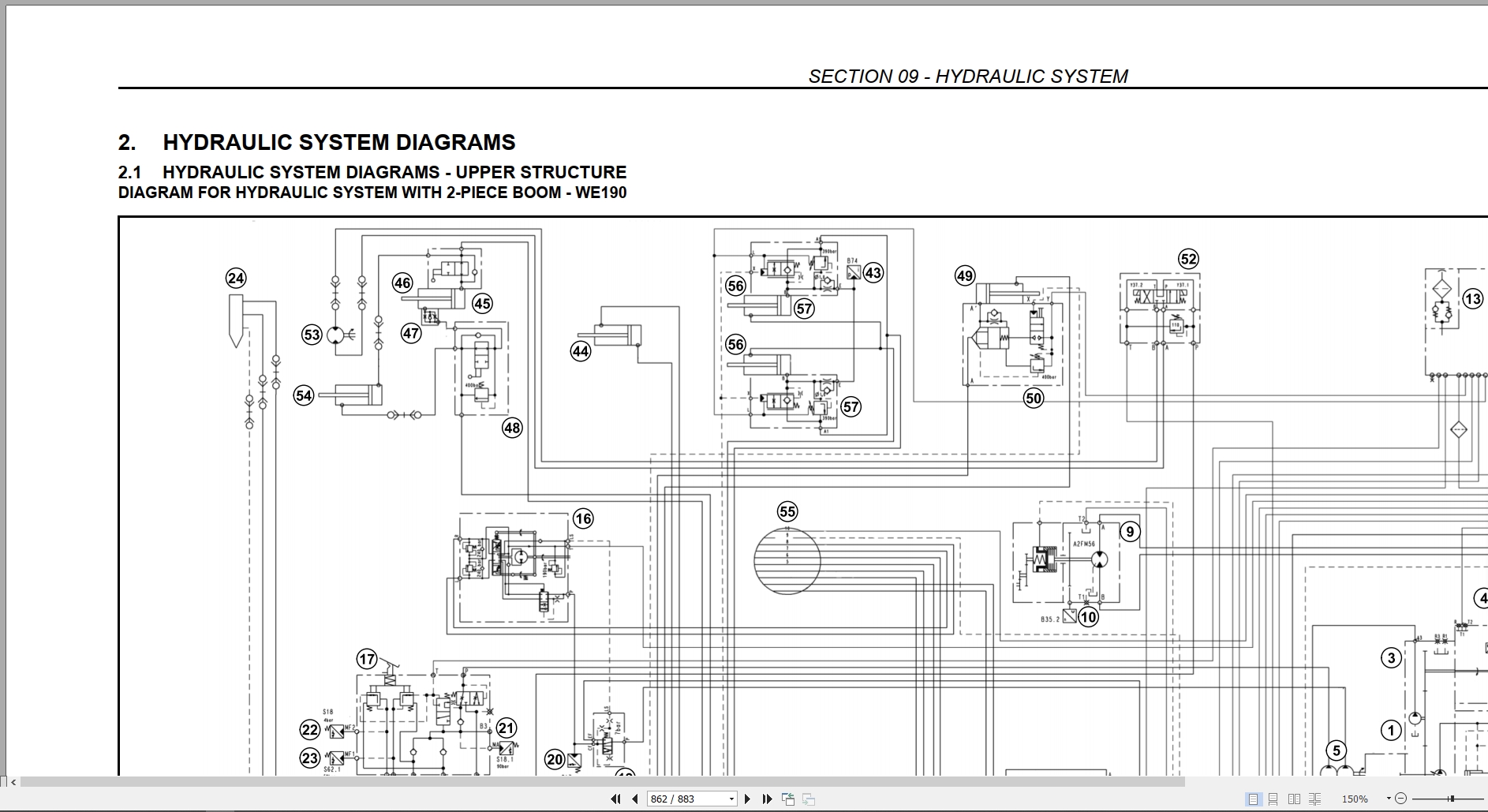
Section 09 – Hydraulic System
1. Hydraulic System
2. Hydraulic System Diagrams
2.1 Hydraulic System Diagrams – Upper Structure
2.2 Hydraulic System Diagrams – Undercarriage
2.3 Hydraulic System Diagrams Blade And/Or Stabilizers
3. Hydraulic Pumps
3.1 Variable-Flow Rate Twin Pump
3.2 Rotation Pump
3.3 Gear Pump
4. Upper Structure Control Valve
5. Undercarriage Control Valve
6. Pilot Control Assy
6.1 Pilot Control Assy Solenoid Valves
7. Rotation System
7.1 Slewing Gearbox
8. Travel
8.1 Travel Motor
9. Stabilization Hydraulic System
10. Boom Hydraulic System
11. Hydraulic System Of Bucket
12. Hydraulic System Of Dipper
13. Hydraulic System Of 2-Piece Boom
14. Hydraulic System With Combination Of Different Functions (Boom, 2-Piece Boom,
Dipper And Bucket)
15. Hydraulic System Of Hammer (With 2-Piece Boom)
16. Hydraulic System Of Hammer And Shears (With 2-Piece Boom)
17. Hydraulic System Of Shears (With 2-Piece Boom)
18. Hydraulic System Of Hammer (With Monoboom)
19. Hydraulic System Of Hammer And Shears (With Monoboom)
20. Hydraulic System Of Shears (With Monoboom)
21. Troubleshooting
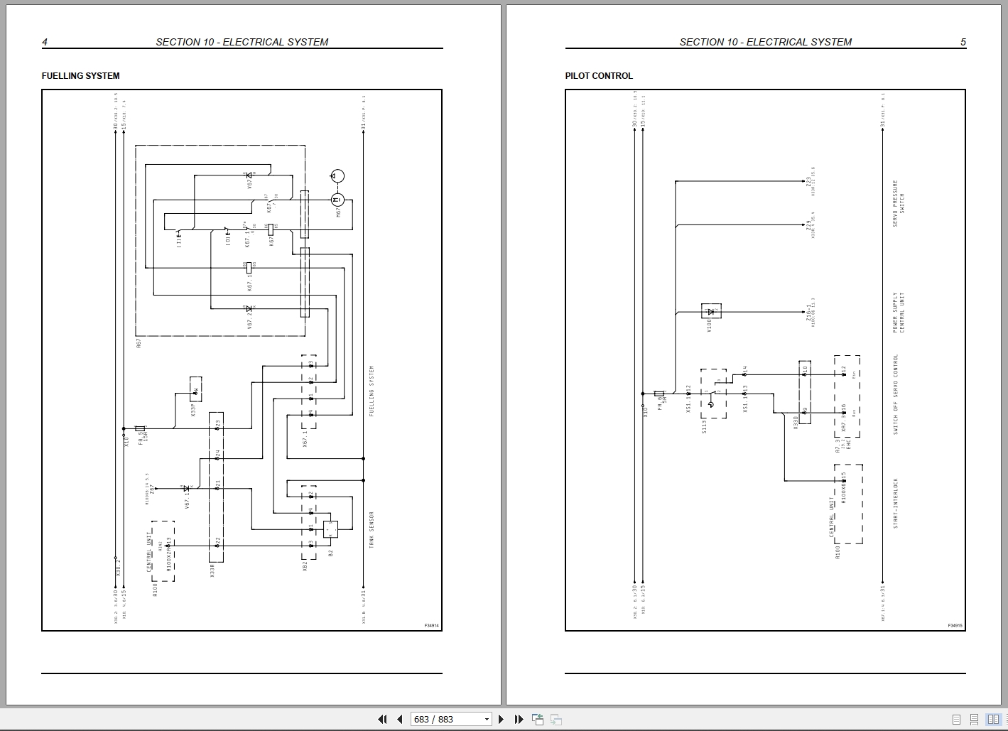
Section 10 – Electrical System
1. Electrical Diagrams
1.1 Electrical Diagrams (We190 – We210 – We230)
1.2 Electrical Diagrams (We210 Industrial – We230 Industrial)
2. Fuses
2.1 Fuses – Replacement
2.2 Batteries – Replacement
2.3 Clamps Check
2.4 Charge
3. Bulbs
3.1 Cab Light
3.2 Front Work Lights
3.3 Boom Work Light
3.4 Travel Light
3.5 Turn Signal Lights
3.6 Rear Floodlamps
4. Troubleshooting
Section 11 – Electronics
1. Main Components
2. Components Of Line 1
2.1 Multi-Function Display
2.2 Central Unit
2.3 Key-Pad Modules
2.4 Power Control System
2.5 Diagnostics Socket
2.6 Electro-Hydraulic Controller
3. Components Of Line Can 2
3.1 Operation
3.2 Central Unit
3.3 Hydraulic Control Levers
3.4 Travel Pedal
3.5 Attachment Pedal (For Hammer And Adjusting Cylinder)
(We190 – We210 – We230, No Industrial Models)
3.6 Power Control System
4. Engine Speed Actuator
4.1 Engine Speed Sensing
5. Coolant Temperature Detection
6. Charge Air Temperature Detection
7. Hydraulic Oil Temperature Detection
8. Proportional Valve – Fan Motor
9. Proportional Valves – Control Block
10. Pilot Control Block
Section 12 – Calibration
1. Necessary Operations Before Calibration
1.1 Calibration Of The Main Pump
1.2 Calibration Of The Rotation Pump
2. Display: Calibration Menu
3. Calibrations With The Engine Running
3.1 Vdo Calibration
3.2 Power Calibration
3.3 Main Valve Calibration (Control Valve)
3.4 Travel Calibration
3.5 Pump Delivery Calibration
3.6 Slewing Pump Calibration
3.7 Auxiliary Pressure Calibration
4. Calibrations With The Engine Stopped
4.1 Calibrations, All Solenoid Valves, Main Pump, Rotation Pump,
Auxiliary Pressure
4.2 Main Valve Calibration (Control Valve)
Section 13 – Fault Codes
1. Error Indication On The Display
2. Central Unit And Engine
2.1 Fault Codes
3. Pcs Unit (Power Control System)
3.1 Fault Codes
4. Hydraulics
4.1 Safety-Related System Diagnostic Faults
4.2 Common Faults
4.3 Can Interface
4.4 Display Indicators
4.5 Key Pads
4.6 Common Digital Inputs
4.7 Hydraulic Control Lever / Pedals
4.8 Pilot Pressure Supply
4.9 Main Pumps
4.10 Attachment Sensors
4.11 Slewing System
4.12 Pilot Valves On Main Valve
4.13 Additional Valves And Sensors
4.14 Automatic Calibration Faults

REALEASE :
04.05.2020
REALEASE :
04.05.2020
REALEASE :
13.04.2022

REALEASE :
08.06.2019
REALEASE :
08.06.2019

REALEASE :
08.06.2019
REALEASE :
08.06.2019

REALEASE :
08.06.2019
REALEASE :
08.06.2019

REALEASE :
17.11.2020
REALEASE :
17.11.2020

REALEASE :
08.06.2019
REALEASE :
08.06.2019
REALEASE :
13.04.2022
 Automotive - Heavy Equipment - Truck & Bus - Forklift - Crane
