
3 ITEMSVIEW CART


Total: 220.00
Expert Support
Full Speed
100% Working
20 USD
Contents:
Preface
Table of Contents
List of Figures
List of Tables
P&H® Mining Equipment Offices
Safe Operating Practices
Definitions of Warnings
Introduction
1.1 Scope
1.2 General Information
1.3 Serial Number Location
1.4 General Safety Precautions
1.5 Lockout and Tagout Procedures
1.6 Sign Maintenance
1.7 Reader Comment Form
1.8 Material Safety Data Sheets (MSDS)
1.9 Warranty
1.10 Mining Shovel Description
1.10.1 Electrical Systems
1.10.2 Hoist System
1.10.3 Crowd System
1.10.4 Swing System
1.10.5 Propel System
1.10.6 Brake Systems
1.11 Mining Shovel Terminology
1.12 Tabulated Data
1.12.1 Operating Specifications
1.12.2 Torque Values
1.12.3 Metric Conversions
1.13 Supernuts™
1.13.1 General
1.14 Tensioning With Supernuts™
1.14.1 SuperNuts™ Removal Procedure (Service under 250˚F)
House Assembly
2.1 General
2.2 House Assembly
2.2.1 Description
2.2.2 Hatch Cover Removal
2.2.3 Hatch Cover Installation
2.2.4 Canopy and House Section Removal
2.2.5 Canopy and House Section Installation
2.3 House Ventilation And Filtration System
2.3.1 Description
2.3.2 Inspection
2.3.3 Filter Cell Cleaning
2.3.4 Adjustments
Swing System
3.1 General
3.2 Description
3.3 Swing Motor And Blower (100J5948F2)
3.3.1 Description
3.3.2 Inspection and Repair
3.3.3 Swing Motor
3.3.4 Swing Motor Blower
3.4 Swing Transmission (100J5949F4)
3.4.1 General
3.4.2 Description
3.4.3 Inspection
3.4.4 Removal
3.4.5 Installation
3.5 Swing Shaft (100J5950F1)
3.5.1 Description
3.5.2 Inspection and Repair
3.5.3 Removal
3.5.4 Disassembly
3.5.5 Cleaning, Inspection, and Repair
3.5.6 Assembly
3.5.7 Installation
3.5.8 Swing Shaft Bearing Capsule Replacement
3.6 Swing Brake
3.7 Swing Roller Circle System
3.7.1 Roller Circle Assembly (R17563F1, R31980F1)
3.7.2 Swing Roller Circle Inspection
3.7.3 Swing System Lubrication Inspection
3.8 Swing Gear (R6216D1)
3.8.1 Description
3.8.2 Inspection and Repair
3.8.3 Tooth Repair
3.9 Swing Ring Gear Installation
3.10 Center Gudgeon Assembly (R17731)
3.10.1 Gudgeon Nut Adjustment
3.11 Key Interlock System
3.11.1 General
3.12 High Voltage Isolation
3.13 Exiting High Voltage Areas
3.14 Padlocks
3.14.1 General Padlock Placement
3.15 High Voltage Collector
3.16 Low Voltage Collector
3.17 Upper Main High Voltage Cabinet
3.17.1 Entrance Procedure
3.18 Installation Of Collector Guard Access Doors
3.18.1 General
3.18.2 Tools and Materials Required
3.18.3 Cutting Openings and Installing Covers
Hoist System
4.1 Description
4.2 Remote Hoist Controller (Optional)
4.2.1 Overview
4.2.2 Procedure
4.3 Hoist Ropes
4.3.1 Inspection
4.3.2 Hoist Rope Reeving
4.4 Hoist Motor And Blower (916J174F3)
4.4.1 Description
4.4.2 Hoist Motor Removal
4.4.3 Hoist Motor Installation
4.4.4 Motor Blower Assembly (R12599D1F1)
4.4.4.1 Description
4.4.4.2 Removal
4.4.4.3 Repair
4.4.4.4 Installation
4.5 Hoist Disc Brake
4.6 Hoist Gearcase (914J364F2)
4.6.1 General
4.6.2 Description
4.6.3 Hoist Gearcase Mounting
4.6.4 Inspection And Repair
4.6.5 Hoist Gearcase Disassembly
4.6.5.1 General
4.6.5.2 Preliminary Preparation
4.6.5.3 Gearcase Cover Removal
4.6.5.4 Intermediate Shaft Assembly Removal
4.6.5.5 First Reduction (Input) Shaft Removal
4.6.5.6 Hoist Drum Shaft Removal
4.6.6 Hoist Gearcase Assembly
4.6.6.1 General
4.6.6.2 Preliminary Preparation
4.6.6.3 First Reduction (Input) Shaft Installation
4.6.6.4 Hoist Drum Seals
4.6.6.5 Hoist Drum Shaft Installation
4.6.6.6 Intermediate Hoist Shaft Installation
4.6.6.7 Hoist Side Stand Shimming
4.6.6.8 Hoist Gearcase Cover Installation
4.6.7 Post Assembly Procedures
4.7 First Reduction (Input) Shaft Assembly (910J664F2)
4.7.1 Description
4.7.2 Inspection
4.7.3 First Reduction (Input) Shaft Disassembly
4.7.4 Inspection and Repair
4.7.5 First Reduction (Input) Shaft Assembly
4.8 Intermediate Hoist Shaft (R1927F1, F4)
4.8.1 Description
4.8.2 Inspection
4.8.3 Hoist Intermediate Shaft Disassembly
4.8.4 Repair
4.8.5 Hoist Intermediate Shaft Assembly
4.9 Hoist Drum Shaft (910J640F6)
4.9.1 Description
4.9.2 Inspection and Repair
4.9.3 Hoist Drum Shaft Disassembly
4.9.4 Hoist Drum Shaft Repair
4.9.4.1 Repair Hoist Drum Lagging Grooves
4.9.4.2 Replacing Removable Hoist Drum Lagging
4.9.5 Hoist Drum Shaft Assembly
Attachment Components
5.1 General
5.2 Description
5.3 Boom Suspension Cables
5.3.1 Description
5.3.2 Inspection
5.3.3 Replacement Criteria
5.3.4 Repair
5.4 Gantry (911J390F5)
5.4.1 Description
5.4.2 Inspection
5.4.3 Repair
5.5 Boom Assembly (100J6527)
5.5.1 Description
5.5.2 Inspection and Repair
5.6 Boom Point Assembly (919N23F2)
5.6.1 Description
5.6.2 Service And Repair
5.6.3 Removal
5.6.4 Disassembly
5.6.5 Assembly
5.6.6 Installation
5.7 Boom Limit Assembly
5.7.1 Description
5.7.2 Boom Jacking
5.7.3 Boom Limit Switch (100J6493F4)
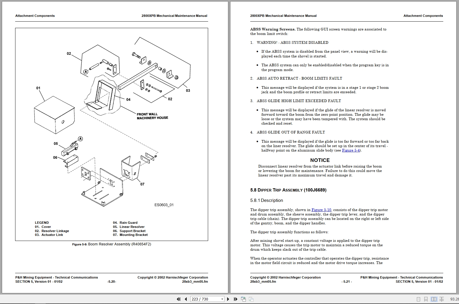
5.7.4 Boom Resolver Assembly (R40654F2)
5.8 Dipper Trip Assembly (100J6689)
5.8.1 Description
5.8.2 Inspection and Repair
5.9 Dipper Trip Motor And Drum Assembly (923J79F2)
5.9.1 Description
5.9.2 Removal
5.9.3 Disassembly
5.9.4 Inspection
5.9.5 Repair
5.9.6 Assembly
5.9.7 Installation
Crowd System
6.1 General
6.2 Description
6.3 Crowd Drive Assembly (100J4494F4)
6.3.1 Description
6.3.2 Preliminary Procedures
6.3.3 Crowd Motor Inspection
6.3.4 Crowd Motor Repair
6.3.5 Crowd Motor Removal
6.3.6 Crowd Motor Installation
6.3.7 Crowd Belt Case
6.3.8 Crowd Motor Sheave
6.3.9 Power Band™ Belt Adjustment
6.3.10 Power Band™ Replacement
6.3.10.1 Preliminary Procedures
6.3.10.2 Replacement
6.4 Crowd Gearcase Assembly
6.4.1 General
6.4.2 Crowd Gearcase Inspection
6.4.3 Crowd Gearcase Repairs
6.4.4 Crowd Gearcase Disassembly
6.4.4.1 General
6.4.4.2 Preliminary Procedures
6.4.4.3 Dipper Handle Removal
6.4.4.4 Saddle Block Removal
6.4.4.5 Crowd Gearcase Cover Removal
6.4.4.6 First Reduction Shaft Removal
6.4.4.7 Second Reduction Shaft Removal
6.4.4.8 Shipper Shaft Removal
6.4.5 Crowd Gearcase Assembly
6.4.5.1 General
6.4.5.2 Shipper Shaft Installation
6.4.5.3 First Reduction Shaft Installation
6.4.5.4 Second Reduction Shaft Installation
6.4.5.5 Crowd Gearcase Cover Installation
6.4.6 Dipper Handle Installation
6.4.7 Shipper Shaft Axial Clearance Adjustments
6.4.7.1 General
6.4.7.2 Inspection
6.4.7.3 Shipper Shaft Axial Clearance Adjustment
6.4.8 Vertical Saddle Block Slide Plate Adjustment
6.4.9 Lateral Saddle Block Slide Plate Adjustment
6.4.10 Contingent Lateral Saddle Block Slide Plate Adjustment
6.5 First Reduction Shaft (910J553F2)
6.5.1 Description
6.5.2 First Reduction Shaft Removal
6.5.3 First Reduction Shaft Disassembly
6.5.4 First Reduction Shaft Inspection
6.5.5 First Reduction Shaft Repair
6.5.6 First Reduction Shaft Assembly
6.5.7 First Reduction Shaft Installation
6.6 Second Reduction Shaft (910J344F3)
6.6.1 Description
6.6.2 Second Reduction Shaft Removal
6.6.3 Second Reduction Shaft Disassembly
6.6.4 Second Reduction Shaft Inspection
6.6.5 Second Reduction Shaft Repair
6.6.6 Second Reduction Shaft Assembly
6.6.7 Second Reduction Shaft Installation
6.7 Shipper Shaft Assembly (R11770)
6.7.1 Description
6.7.2 Shipper Shaft Removal and Disassembly
6.7.3 Shipper Shaft Inspection
6.7.4 Shipper Shaft Repair
6.7.5 Shipper Shaft Gear Shimming
6.7.6 Shipper Shaft Assembly and Installation
6.8 Dipper Handles (R11750)
6.8.1 General
6.8.2 Description
6.8.3 Visual Inspection
6.8.4 Weld Inspection
6.8.5 Dimensional Inspection
6.8.6 Dipper Handle Spacer Installation
6.8.7 Repairing Dipper Handle Cracks
6.8.8 Dipper Handle Rack Replacement
6.8.9 Welding Rack Sections
6.8.10 Installing Rack Sections
6.8.10.1 Dimensions To Maintain
6.8.11 Rack Installation Procedure – Manganese Racks
6.8.12 Rack Installation – Alloy Racks
6.9 Rack Section Replacement
6.10 Crowd Disc Brake
6.11 Crowd Limit Switch Sensor (979J247F1)
6.11.1 Description
6.11.2 Variable Transformer (Resolver) Replacement
6.11.3 Limit Switch Sensor Removal
6.11.4 Limit Switch Sensor Installation
Propel System
7.1 General
7.2 Description
7.3 Propel Motor
7.3.1 General
7.3.2 Description
7.3.3 Inspection
7.3.4 Repair
7.3.5 Propel Motor Removal
7.3.6 Propel Motor Installation
7.3.7 Propel Motor Alignment
7.3.7.1 General
7.3.7.2 Horizontal Angularity Alignment
7.3.7.3 Horizontal Offset Alignment
7.3.7.4 Vertical Parallelism Alignment
7.3.7.5 Vertical Offset Alignment
7.3.7.6 Final Alignment Procedures
7.3.7.7 Facial Gap Adjustment
7.4 Propel Brake (15R15D7)
7.5 Propel Motor Blower
7.5.1 Removal
7.5.2 Repair
7.5.3 Installation
7.6 Propel Transmission (100J5800F2)
7.6.1 Description
7.6.2 Removal
7.6.3 Repair
7.6.4 Installation
7.6.4.1 General
7.6.4.2 Installation Procedure
7.7 Crawler Component Maintenance
7.7.1 Introduction
7.7.2 Pitch Mismatch and Track Tension Inspection
7.7.2.1 General
7.7.2.2 Inspection Procedure
7.7.3 Pitch Mismatch Solutions
7.7.4 Results of Appropriate Repairs
7.7.5 Additional Track Repair Options
7.8 Crawler Track Assembly
7.8.1 Description
7.8.2 Inspection
7.8.3 Track Removal
7.8.4 Repairing Crawler Shoes
7.8.4.1 Crawler Belt Installation
7.8.4.2 Crawler Track Adjustment
7.9 Lower Roller Assembly (R19768F1, F2)
7.9.1 Description
7.9.2 Inspection
7.9.3 Removal and Disassembly
7.9.4 Repairs
7.9.5 Installation and Assembly
7.10 Front Idler Rollers (910J653F1)
7.10.1 Description
7.10.2 Inspection
7.10.3 Removal and Disassembly
7.10.4 Repair
7.10.5 Assembly and Installation
7.11 Rear Idler Assembly (913N63F1)
7.11.1 General
7.11.2 Description
7.11.3 Inspection
7.11.4 Removal and Disassembly
7.11.5 Repair
7.11.6 Assembly and Installation
7.12 Crawler Drive Shaft (910J665F1, F2)
7.12.1 Description
7.12.2 Inspection
7.12.3 Removal and Disassembly
7.12.4 Repair
7.12.5 Assembly and Installation
7.13 Tensioning Crawler Side Frame Studs
7.13.1 Side Frame Rod Bolt Tensioning Values – Various Methods
7.13.2 Side Frame Rod Bolt Tensioning with Hydraulic Kit (R17981F3, F4)
7.13.2.1 General
7.13.2.2 Procedure for Tensioning Side Frame Rod Bolts
Air System
8.1 Description
8.1.1 General
8.1.2 Upper Air System and Controls (100J6250F2)
8.1.3 Redundant Brake Solenoid Systems
8.1.4 Causes of Redundant Crossover System Failures
8.1.5 Valve Failure Test Procedure
8.1.6 Preventive Maintenance
8.1.7 Immediate Causes of Valve Failures
8.1.8 Underlying Causes of Valve Failures
8.1.9 Lower Air Control Panel
8.2 Lube Air Pump Control Panel
8.3 Quick Release Valve (36Z240D11, D12)
8.3.1 Description
8.3.2 Maintenance and Repair
8.4 Solenoid Valves
8.4.1 General
8.4.2 Solenoid Brake Valves
8.4.3 Solenoid Valve Maintenance
8.5 Receiver Drain System
8.5.1 Description
8.6 Air System Pressure Switches
8.6.1 Air Receiver Pressure Switch
8.6.2 Brake System Pressure Switches
8.7 Air Regulators
8.7.1 General
8.7.2 Air Regulator – Upper Brakes and Lubrication
8.7.3 Air Regulator/Filter – Solenoid Spool Assist
8.7.4 Adjustment
8.7.5 Disassembly
8.7.6 Inspection
8.7.7 Assembly
8.7.8 Troubleshooting
8.8 Air Lubricator (46Z405)
8.8.1 Maintenance
8.8.2 Repair
8.9 Air Lubricator (46Q38D9)
8.9.1 Description
8.9.2 Lubricator Adjustment
8.10 Air Filters
8.10.1 Air System And Boarding Stairway (46Z355D4 and 46Q39D9)
8.10.2 Air Filter – Brake Valve Pilot (46Z515)
8.11 Deicer
8.12 Air System Dryers
8.13 Boarding Stairway Air System
8.13.1 Description
8.13.2 Boarding Stairway Components
8.13.3 Air Filter
8.13.4 Air Lubricator
8.13.5 Air Pressure Regulator
8.14 Boarding Stairway Air Cylinder (38Q136)
8.14.1 Description
8.14.2 Removal
8.14.3 Disassembly
8.14.4 Inspection
8.14.5 Assembly
8.14.6 Installation
8.15 Filter Vibrator Kit (R11233F1)
Maintenance Welding
9.1 General
9.2 Introduction
9.3 Weld Inspection
9.3.1 Regular Inspection
9.3.2 Unscheduled Inspection
9.3.3 Preparation for Inspection
9.3.3.1 Surface Cleaning
9.3.3.2 Access Doors and Holes
9.3.3.3 Scaffolding and Bracket Attachment
9.4 Weld Repairs
9.4.1 Type of Weld Repair
9.4.2 Base Metal Assessment
9.4.3 Weld Repair Assessment
9.5 Welding Process
9.5.1 Weld Process Selection
9.5.2 Weld Process Factors
9.5.2.1 Base Metal Type
9.5.2.2 Joint Design and Thickness
9.5.2.3 Welding Position
9.5.2.4 Environmental Conditions
9.5.2.5 Availability of Equipment
9.5.2.6 Weld Process Summary
9.6 Weld Filler Metals and Electrodes
9.6.1 Filler Metal Selection
9.6.2 Filler Metal and Electrode Classifications
9.6.3 Electrode Handling and Storage
9.7 Weld Preparation
9.7.1 Types of Weld Defects
9.7.2 Weld Preparation Steps
9.8 Weld Repair Steps
9.9 Welding Precautions For Austenitic Manganese Steel (P&H 7)
9.9.1 Weld Defect Repair
9.10 Weld Heating (Other Than Austenitic Manganese Steel)
9.10.1 Weld Preheat Guidelines
9.10.2 Post Weld Heat Treatment (PWHT)
9.11 Weld Repair – Final Cleaning and Finish
9.12 Splicing Requirements
9.12.1 One-Inch Plates and Under
9.12.2 Plates Over One Inch
9.12.3 Control of Distortion and Shrinkage
9.12.3.1 Angular Distortion
9.12.3.2 Transverse Shrinkage
9.12.4 Complete Penetration of Groove Weld
9.13 Welding Guidelines
9.13.1 Scope
9.13.2 Purpose
9.13.3 Weld Definitions
9.13.4 Bead and Fillet Weld Guidelines
9.13.4.1 Convexity of Fillet Welds
9.13.4.2 Concavity of Fillet Welds
9.13.5 Butt Weld Guidelines
9.13.5.1 Undercut and Wash
9.13.5.2 Overlap
9.13.5.3 Porosity
9.13.5.4 Slag Inclusions
9.13.5.5 Lack of Fusion
9.13.5.6 Crater Cracks
9.13.5.7 Craters
9.13.5.8 Standards for Weld Grinding
9.13.5.9 Weld Symbol Definitions
Lubrication System
10.1 Description
10.2 Electric Motor Lubrication
10.2.1 General
10.2.2 Lubrication
10.2.3 Lubrication Intervals
10.2.4 Lubrication Procedures
10.3 Grease Selection
10.4 Installing Replacement Motor
10.5 Lubrication After Extended Storage
10.6 Automatic Lubrication System
10.6.1 Description of Controls
10.6.2 Operating in Cold Conditions
10.6.3 Lube Room Control Panels
10.6.3.1 General
10.6.3.2 Push-buttons
10.6.3.3 Alarms
10.6.4 Control Cabinet
10.6.5 Control Cabinet Touchscreen
10.6.5.1 General
10.6.5.2 Checking Or Changing Preset Times
10.7 Automatic Lubrication System Troubleshooting
10.8 Inspection
10.9 System Operation
10.10 System Start-up
10.11 Lubrication Pumps
10.11.0.1 Description
10.11.0.2 Repair
10.11.0.3 Installation
10.12 Farval Components
10.12.1 Measuring Valves
10.12.1.1 General
10.12.1.2 Description
10.12.1.3 Measuring Valve Operation – Type DD Valve Configured For Dual Discharge
10.12.1.4 Measuring Valve Operation – Type DD Valve Configured For Single Discharge And Type DM V…
10.12.1.5 Measuring Valve Adjustment
10.12.1.6 Measuring Valve Removal
10.12.1.7 Type DM Measuring Valve Disassembly
10.12.1.8 Measuring Valve Inspection And Repair
10.12.1.9 Type DM Measuring Valve Assembly
10.12.1.10 Type DD Measuring Valve Disassembly
10.12.1.11 Measuring Valve Inspection And Repair
10.12.1.12 Type DD Measuring Valve Assembly
10.12.1.13 Measuring Valve Installation
10.12.2 Reversing Valves
10.12.2.1 Reversing Valve Operation
10.12.2.2 Reversing Valve Adjustment
10.13 Lincoln Components
10.13.1 General
10.13.2 Description
10.13.3 Injectors
10.13.3.1 Description
10.13.3.2 Injector Operation – SL-1 And SL-11
10.13.3.3 Injector Operation – SL-32
10.13.3.4 Injector Adjustment – SL-1 And SL-11
10.13.3.5 SL-32 Injector Adjustment
10.13.3.6 SL-1 Injector Removal
10.13.3.7 SL-1 Injector Disassembly
10.13.3.8 SL-1 Injector Repair
10.13.3.9 SL-1 Injector Assembly
10.13.3.10 SL-1 Injector Installation
10.13.3.11 SL-11 Injector Removal
10.13.3.12 SL-11 Injector Disassembly
10.13.3.13 SL-11 Injector Repair
10.13.3.14 SL-11 Injector Assembly
10.13.3.15 SL-11 Injector Installation
10.13.3.16 SL-32 Injector Removal
10.13.3.17 SL-32 Injector Disassembly
10.13.3.18 SL-32 Injector Repair
10.13.3.19 SL-32 Injector Assembly And Installation
10.13.4 Vent Valve Assemblies
10.13.4.1 General
10.13.4.2 Description
10.13.4.3 Vent Valve Assembly Operation
10.13.4.4 Vent Valve Removal
10.13.4.5 Vent Valve Disassembly
10.13.4.6 Vent Valve Repair
10.13.4.7 Vent Valve Assembly
10.13.4.8 Vent Valve Installation
10.13.4.9 Elbow Union Removal And Disassembly
10.13.4.10 Elbow Union Repair
10.13.4.11 Elbow Union Assembly And Installation
10.13.5 Spray Valves (R5808F3, F6)
10.13.5.1 Description
10.13.5.2 Removal
10.13.5.3 Repair
10.13.6 Pressure Switches
10.13.6.1 Description
10.13.6.2 Adjustment
10.14 Replacing Lubrication Components
10.14.1 General
10.14.2 Description
10.14.2.1 Removal
10.14.2.2 Installation
10.14.3 Bleeding Air From Supply Lines
10.14.3.1 Bleeding Air From Supply Lines – System
10.14.3.2 Bleeding Air From Supply Lines – Component Replacement
10.14.3.3 Bleeding Air From Feeder Lines
10.15 Hoist Gearcase Lubrication System (100J6526F2)
10.15.1 Description
10.15.2 Maintenance
10.15.2.1 General
10.15.2.2 Inspection
10.16 Swing Gearcase Lubrication (R10044F1, F2)
10.16.1 Description
10.16.2 Maintenance
10.16.2.1 General
10.16.2.2 Inspection
10.17 Crowd Gearcase Lubrication System (R47958F1)
10.17.1 Description
10.17.2 Maintenance
10.17.2.1 General
10.17.2.2 Inspection
10.17.3 Oil Filters (46U110D1, D2)
10.17.3.1 Description
10.17.3.2 Disassembly
10.17.3.3 Maintenance
10.17.3.4 Assembly
10.17.4 Oil Strainer (46Q108)
10.17.4.1 Servicing
10.17.5 Lubrication Pump (37Z331D2)
10.17.5.1 General
10.17.5.2 Description
10.17.5.3 Removal
10.17.5.4 Replacing The Shaft Seal
10.17.5.5 Disassembly
10.17.5.6 Inspection And Repair
10.17.5.7 Assembly
10.17.5.8 Installation
10.18 Hoist And Crowd Lube Pump Flexible Coupling (18Z3706D2, D3)
10.18.1 Description
10.18.2 Alignment
10.19 Swing Lube Pump Flexible Coupling (18Z3706D4)
10.19.1 Description
10.19.2 Alignment
10.20 Gear Reducer (53Z801)
10.20.1 Description
10.20.2 Maintenance
10.20.3 Removal
10.20.4 Disassembly
10.20.5 Inspection and Repair
10.20.6 Assembly
10.21 Gearcase Capacities
10.22 Lubrication Specifications
10.22.1 General
10.22.2 P&H Material Specifications
10.22.3 P&H Material Specification 472 – Multi-Purpose Grease: Extreme Pressure (EP)
10.22.4 P&H Material Specification 464 – Open Gear Lubricant
10.22.5 P&H Material Specification 451 – Heavy Duty Motor Oil
10.22.6 P&H Material Specification 497 – Multi-Purpose Gear Oil – Single Viscosity; Extreme Press…
10.22.7 P&H Material Specification 520 – Multi-Service Mining Lubricant
10.22.8 Grease Versus Open Gear Lube
10.22.9 Selection of Gearcase Oils
10.22.10 ISO Grades Of Oil
Disc Brakes
11.1 General
11.2 Disc Brake Operation
11.2.1 General
11.2.2 Brake Hold Mode
11.2.2.1 Causes of Brake Hold Mode
11.2.2.2 Brake Hold Mode Override
11.2.3 Hoist Brake(s)
11.2.4 Crowd Brake
11.2.5 Propel Brake
11.2.6 Swing Brake
11.3 Releasing Disc Brakes For Maintenance
11.3.1 Description
11.3.2 Preliminary Procedures for Releasing Brakes
11.3.3 Releasing Hoist, Crowd, or Swing Brakes for Maintenance
11.3.3.1 Releasing Hoist, Crowd, or Swing Brakes Using the Operator’s Controls
11.3.3.2 Releasing Hoist, Crowd, or Swing Brakes With an External Air Supply
11.3.4 Releasing Propel Brakes for Maintenance
11.3.5 Disc Brakes That Can Not Be Released
11.4 Inspecting Disc Brakes
11.4.1 Tools and Equipment Required
11.4.2 Preventive Maintenance (PM) Inspection Every 250 Hours
11.4.2.1 General
11.4.2.2 Visual Inspection
11.4.2.3 Mechanical Inspection
11.5 Other Inspections
11.6 Disc Brake Data
11.6.1 Swing Brake (15R14D1)
11.6.2 Crowd Brake (15R13D3)
11.6.3 Propel Brake (15R15D7)
11.6.4 Hoist Brake (R27275D1)
11.6.5 Weights
11.7 Removing Air Gap Split Shims
11.7.1 Tools and Equipment Required
11.7.2 Description
11.7.3 Removing Air Gap Split Shims Procedure
11.8 Removing Disc Brakes – Normal Conditions
11.8.1 Tools and Equipment Required
11.8.2 Removing Disc Brakes Procedure (Normal)
11.9 Removing Disc Brakes – Special Conditions
11.9.1 Tools and Equipment Required
11.9.2 Description
11.10 Installing Disc Brakes
11.10.1 Tools and Equipment Required
11.10.2 Installing Disc Brakes Procedure
11.10.3 Shimming the Swing Brake
11.11 Removing And Replacing O-ring and Felt Seals
11.11.1 General
11.11.2 Tools and Equipment Required
11.11.3 Inspection for O-ring Leakage
11.11.4 Removing and Replacing O-rings
11.11.4.1 Remove And Replace O-rings On The Shovel As Follows:
Air Compressors
A.1 Description
A.2 Rotary Screw Compressor (R36961) Sullair Type Es-8
A.2.1 Air Control Description
A.2.1.1 Compressor Modulation
A.2.1.2 Compressor Unloading
A.2.1.3 Compressor Programmed Set Points
A.2.1.4 Dual Compressor Operation
A.2.1.5 Touchpad Operation
A.2.1.6 Status Displays
A.3 Rotary Screw Compressor – Quincy Rotary Screw
A.3.1 Air Control Description
A.4 Quincy Reciprocating (Piston Type) Air Compressor
A.4.1 General
A.4.2 Lubrication
A.4.3 Oil Pressure Adjustment
A.4.4 Adjusting Belt Tension
Air Dryers
B.1 Introduction
B.2 Air Dryer (R37969F1/F2)
B.2.1 General
B.2.2 Operation
B.2.3 Maintenance
B.3 Desiccant Air Dryer System (100J6572)
B.3.1 General
B.3.2 Description
B.3.3 Air Dryer Input
B.3.4 Air Dryer (46Q121)
B.3.5 Air Dryer Cycles
B.3.6 Air Dryer Output
B.3.7 Air Filter – Dryer After Filter (46Z469)
B.3.8 Air Filter – Oil Removal (46Z406)
SnubRite® Hydraulic Snubber
C.1 Introduction
C.1.1 General
C.1.2 Description
C.1.3 SnubRite® Nameplates And Decals
C.1.4 SnubRite® Serial Number Plate
C.1.5 SnubRite® Product Warranty Registration Card
C.2 Installation
C.2.1 General
C.2.2 Snubber Lifting
C.2.2.1 Description
C.2.2.2 Snubber Lifting Procedure
C.2.3 Mounting Lugs
C.2.4 Installation
C.2.5 Maintenance
C.2.5.1 Snubber Replacement Criteria
C.2.6 Rebuild Schedule
C.3 Repair Parts
Index
Reader Comment Form

REALEASE :
REALEASE :
REALEASE :
REALEASE :

REALEASE :
25.05.2019
REALEASE :
25.05.2019
REALEASE :
REALEASE :
REALEASE :
REALEASE :
REALEASE :
REALEASE :
REALEASE :
REALEASE :
REALEASE :
26.06.2019
REALEASE :
26.06.2019
 Automotive - Heavy Equipment - Truck & Bus - Forklift - Crane