
0 ITEMSVIEW CART


✓
Expert Support
✓
Full Speed
✓
100% Working
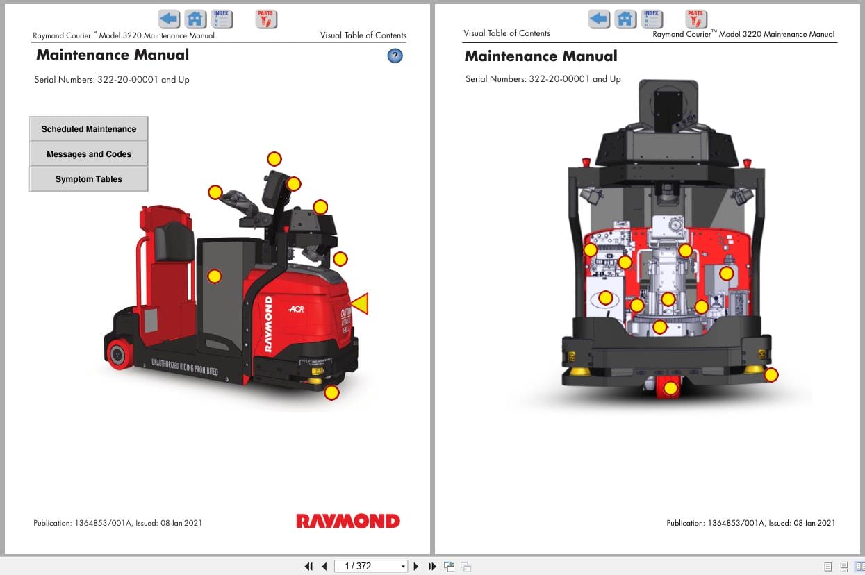
Raymond Automation 3220 Maintenance Manual 1364853001A 2021
Size: 12.03 MB
Format: PDF
Language: English
Brand: Raymond
Type of Machine: Automation, Automated Tow Tractor
Type of Manual: Maintenance Manual, Electrical Schematic
Model: Raymond Courier 3220 Automated Tow Tractor
Serial Number: 322-20-00001 and Up
Part Number: 1364853001A
Issue Date: 2021
Number of Pages: 372 Pages
30 USD
- Description
Description
Contents:
Section 1. How To Use This Manual
Manual Design
Interactive Electronic Technical Manuals
Abbreviations & Symbols
Section 2. Safety
Definitions
General Safety
Battery Safety
Jacking Safety
Tie-Down for Transport
Towing
Static Safety
Welding Safety
Section 3. Systems Overview
Introduction
Raymond Courier Model Identification
Raymond Courier Specifications
Special Tools
Operator Display and Programming
Automated Truck
Graphical Operator Interface (GOI)
Guidance System Overview
FlashWare
Section 4. Scheduled Maintenance
Maintenance Guidelines
Initial 90 Day/250 Deadman Hours (HD) Maintenance
Every 180 Days or 500 Deadman Hours
Every 360 Days or 2000 Deadman Hours (HD)
Contactor Tip Inspection
Section 5. Troubleshooting
How to Use This Section
Electrical Troubleshooting Guidelines
Fuses
AC Electric Motors
Symptom Tables: Travel (Forward/Reverse) System
Symptom Tables: Wiring System
Symptom Tables: Guidance System
Section 6. Messages and Codes
List of Messages and Codes
Traction Amplifier LED Diagnostics
Traction Amplifier Flash Codes
Caution and Error Codes
Message and Caution Codes
Error Codes
GOI Message Reference
Section 7. Component Procedures
List of Component Procedures by Truck System
Component Locator Photos
Steering and Controls
Drive and Brake
Electrical Components
Guidance System Components
Options
Section 8. Theory of Operation
Definitions
Traction System
Theory of Operation – Electric Power Steering
Pinout Matrix
Section A. Appendix
Lubrication Equivalency Chart
Thread Adhesives, Sealants, and Lubricants
Component Specific Service/Torque Chart
Torque Chart – Standard (Ferrous)
Torque Chart – Standard (Brass)
Torque Chart – Metric (Ferrous)
Torque Chart – Metric (Brass)
Torque Chart – Thread Forming Screws
Torque Chart – Metric Thread-Forming Screws
Torque Chart – Hydraulic Fittings
Torque Chart – Straight Thread Face Seal O-Rings
Decimal Equivalent Chart
Standard/Metric Conversions
Section I. Index
Schematics
Figure 1. Model 3220 Automated Tow Tractor
Figure 2. Vehicle Interface Module, Automated Truck Guidance and Navigation
Figure 3. Model 3030 Guidance and Navigation System (Continued)
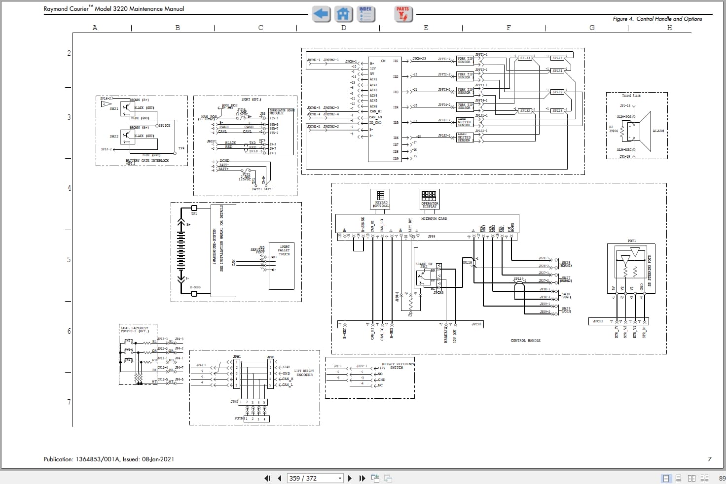
Figure 4. Control Handle and Options
Figure 5. Low Clearance (Short) Arch
Figure 6. Component Legend (Page 1 of 2)
Figure 7. Component Legend (Page 2 of 2)
Figure 8. Power Distribution Diagram
RSIs
Scheduled Maintenance – Software Updates
360 Day/2000 Hour Inspection – Power Steering Electrical Connectors
VSM Software 3.1.5 is now available
Energy Power System Power Source Limiting Option
New VSM Software 3.1.4 for Raymond Courierâ„¢ tow tractors
Related Products
-
RAYMOND Forklift Service Parts Manual Schematics 2020
Original price was: 300.110Current price is: 110. USDThis is a service information package, you will need to use this to repair a vehicleHot-63%
REALEASE :
REALEASE :
-
Raymond iW.RTLS Installation Maintenance Manuals
20 USDSize: 12.02 MBFormat: PDFLanguage: EnglishBrand: RaymondType of Machine: iWAREHOUSE RTLSType of Manual: Installation Manual, Maintenance Manual, Electrical SChematic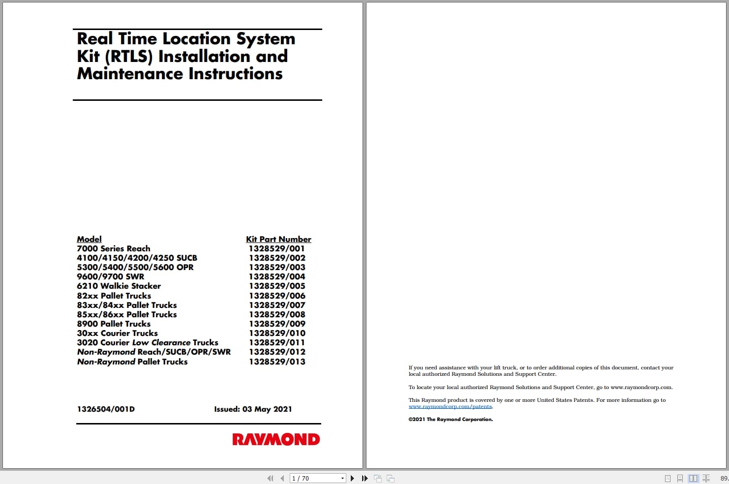
REALEASE :
REALEASE :
-
Raymond iWH iW.FieldSense Installation User Guide Manuals
20 USDSize: 15.88 MBFormat: PDFLanguage: EnglishBrand: RaymondType of Machine: iWAREHOUSE iW.FieldSenseBType of Manual: Installation Manual, User Manual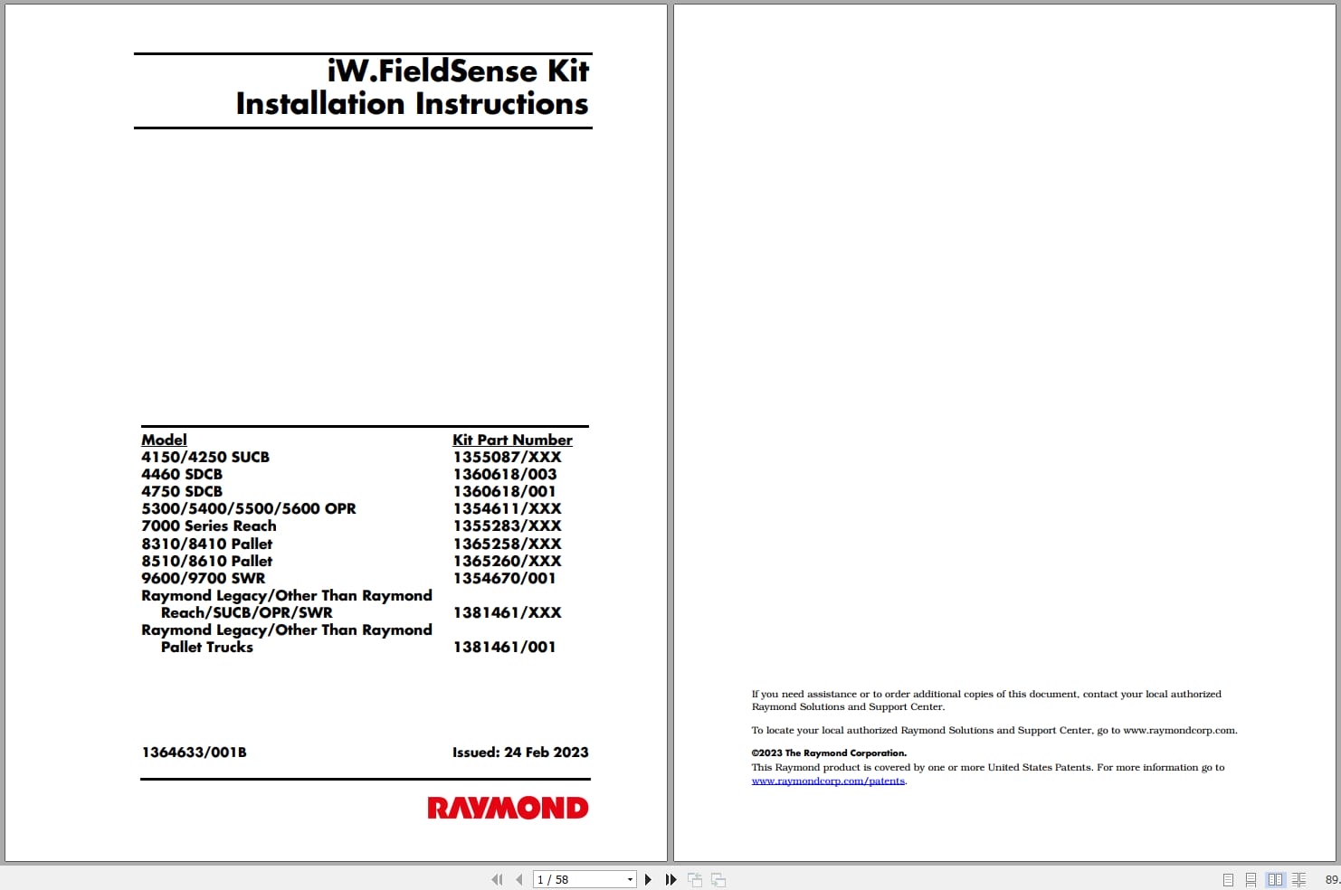
REALEASE :
REALEASE :
-
Raymond iW.ObjectSense Installation Maintenance Manuals
20 USDSize: 22.14 MBFormat: PDFLanguage: EnglishBrand: RaymondType of Machine: iWAREHOUSE ObjectSenseType of Manual: Installation Manual, Maintenance Manual
REALEASE :
REALEASE :
-
Raymond iW Evolution Installation Maintenance User Guide Manuals
20 USDSize: 106.70 MBFormat: PDFLanguage: EnglishBrand: RaymondType of Machine: iWAREHOUSEType of Manual: Installation Manual, Maintenance Manual, User Manual, Electrical Schematic
REALEASE :
REALEASE :
-
RAYMON Forklift Technical Publication Library 2015 DVD NEW VERSION
Original price was: 300.150Current price is: 150. USDRAYMON Forklift Technical Publication Library 2015 DVDSize: 4,0Gb PackFormat: PDF, JavaLanguage: EnglishBrand: RAYMONType of machine: RAYMON ForkliftAmount of DVD: 1 DVD rarVersion 5.2.49Type of document:Technical Publication LibraryService Manual (Including in Maintenance Manual)Maintenance ManualParts ManualSchematics ManualYear: 2013-2015Hot-50%
REALEASE :
08.04.2020
REALEASE :
08.04.2020
-
Raymond iPort Kit Installation and Maintenance Manual 1089339001H 2019
20 USDSize: 6.54 MBFormat: PDFLanguage: EnglishBrand: RaymondType of Machine: iPortType of Manual: Maintenance Manual, Kit Installation ManualApplicable Model:4100, 4150, 4200, 4250, 4750 Counterbalanced5400, 5500, 5600 Orderpicker7200, 7300, 7310, 7400, 7420, 7440, 7500, 7520, 7600, 7620, 7640, 7700, 7720 Reach Trucks9600, 9700 Swing-Reach Trucks8300, 8310, 8400, 8410, 8500, 8510, 8720, 8900 Pallet Trucks8600, 8610 Tow TractorsPart Number: 1089339001HPublication Date: 2019Number of Pages: 132 Pages
REALEASE :
REALEASE :
-
Raymond iW Essential Schematic Installation Manuals
20 USDSize: 47.24 MBFormat: PDFLanguage: EnglishBrand: RaymondType of Machine: iWAREHOUSE EssentialType of Manual: Installation Manual, Electrical Schematic
REALEASE :
REALEASE :