
0 ITEMSVIEW CART

✓
Expert Support
✓
Full Speed
✓
100% Working
Raymond iW Evolution Installation Maintenance User Guide Manuals
Size: 106.70 MB
Format: PDF
Language: English
Brand: Raymond
Type of Machine: iWAREHOUSE
Type of Manual: Installation Manual, Maintenance Manual, User Manual, Electrical Schematic
20 USD
- Description
Description
List of Files:
12 Volt Time Delay Relay Installation Instructions.pdf (6 Pages)
Index
Time Delay Relay Installation on 12 Volt Trucks
Kit Component
Installation
Time Delay Wiring Diagram
7 In. Display Implementation Guide.pdf (62 Pages)
Index
Cover Page
General
Compliance Statements
Field Installation Parts
Display and Dash Panel
System Block Diagram
Kit Field Installation
Install Display S/W and Reconfigure Truck
Dashboard – iWAREHOUSE Not Enabled
Program Mode – iWAREHOUSE Not Enabled
Configure Truck for iWAREHOUSE
iWAREHOUSE Login
Dashboard – iWAREHOUSE Enabled
Program Mode – iWAREHOUSE Enabled
Network
Task Selection
Messages
Battery Submenu
Statistics Submenu
Impact Processing Module (IPM)
Troubleshooting
Codes and Tests
Theory of Operation
Schematic
Glossary
Electrical Schematic.pdf (6 Pages)
Index
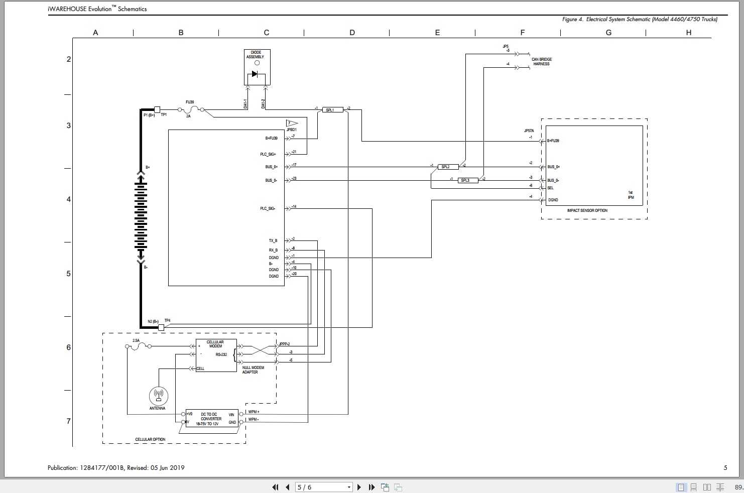
iWAREHOUSE Evolution Schematic
Figure 1. Electrical System Schematic (4150/4250 Counterbalanced, 7000 Series Reach-Fork, Tractor Mounted 5000 Series Orderpicker, 6210 Walkie Stackers, and Pallet Trucks Except 82×0)
Figure 2. Electrical System Schematic (9600/9700 Swing-Reach® Trucks)
Figure 3. Electrical System Schematic (Model 8210/8250 Trucks)
Figure 4. Electrical System Schematic (Model 4460/4750 Trucks)
Figure 5. Electrical System Schematic (Platform Mounted 5000 Series Orderpicker Trucks)
Installation Cellular Modem Kit.pdf (28 Pages)
Index
Cover Page
Compliance Statements
Before You Begin
Parts Required
Installation Part Kit
Installation
Set Cellular Configuration in the iMONITOR Unit
LED Indicators
Troubleshooting
Installation Non-iPORT Big Joe J1-192.pdf (28 Pages)
Index
Big Joe J1-192
Getting Started
General Guidelines
Required Tools
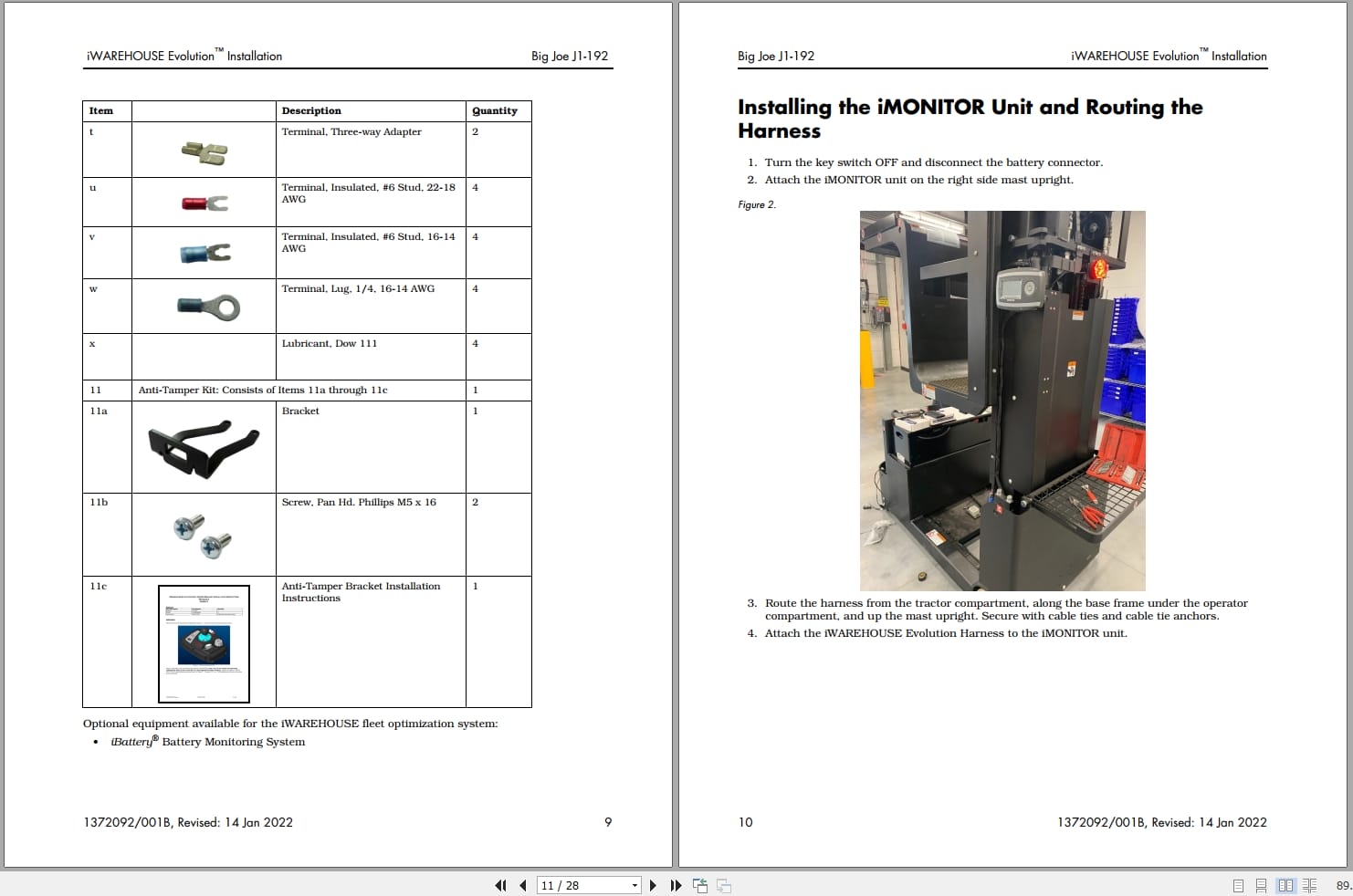
System Components
Installing the iMONITOR Unit and Routing the Harness
Input Power
Installing the UPM
Installing the Alarm
Access Control
Slow Down on Impact
Lift Interrupt on Impact
Hour Meter Monitoring
UPM Jumpers
Impact Processing Module
Connecting and Programming with FlashWare
Upon Completion
Wiring Diagram – Big Joe J1-192
Installation Non-iPORT Caterpillar E3500.pdf (30 Pages)
Index
Cover Page
Caterpillar Model E3500 Installation
Getting Started
General Guidelines
Required Tools
System Components
Installing the iMONITOR Unit and Routing the Harness
Input Power
Installing the UPM
Installing the Alarm
Access Control
Slow Down on Impact
Hour Meter Monitoring
UPM Jumpers
Impact Processing Module
Connecting and Programming with FlashWare
Upon Completion
Wiring Diagram – Caterpillar E3500 Counterbalance Truck
Installation Non-iPORT Crown 5725.pdf (28 Pages)
Index
Crown Model 5725
Getting Started
General Guidelines
Required Tools
Additional Parts Required
Passkeys
System Components
Installing the iMONITOR Unit and Routing the Harness
Input Power
Installing the UPM
Installing the Alarm
Access Control
Slow Down on Impact
Hour Meter Monitoring
Key Hours
Deadman Hours
Lift Hours
Travel Hours
UPM Jumpers
Impact Processing Module
Programming
iMONITOR Unit
Universal Processing Module
UPM FlashWare Set-up Screen Shot
Upon Completion
Wiring Diagram – Crown Reach Truck Model 5725
Installation Non-iPORT Crown MT Stacker.pdf (28 Pages)
Index
Crown MT Stacker
Getting Started
General Guidelines
Required Tools
System Components
Installing the iMONITOR Unit and Routing the Harness
Input Power
Installing the UPM
Installing the Alarm
Access Control
Slow Down on Impact
Hour Meter Monitoring
Impact Processing Module
Connecting and Programming with FlashWare
Upon Completion
Wiring Diagram – Crown MT Stacker
Installation Non-iPORT Crown PE4500-60.pdf (26 Pages)
Index
Crown Model PE4500-60 Installation
Getting Started
General Guidelines
Required Tools
System Components
Installing the iMONITOR Unit and Routing the Harness
Input Power
Installing the UPM
Installing the Alarm
Access Control
Slow Down on Impact
Hour Meter Monitoring
UPM Jumpers
Impact Processing Module
Programming
Upon Completion
Wiring Diagram – Crown Pallet Truck Model PE4500-60
Installation Non-iPORT Crown RC5500.pdf (28 Pages)
Index
Crown Model RC5500 Installation
Getting Started
General Guidelines
Required Tools
System Components
Installing the iMONITOR Unit and Routing the Harness
Input Power
Installing the UPM
Installing the Alarm
Access Control
Slow Down on Impact
Hour Meter Monitoring
UPM Jumpers
Impact Processing Module
Programming
Upon Completion
Wiring Diagram – Crown Stand-Up End Control Model RC5500
Installation Non-iPORT Crown RD5265.pdf (30 Pages)
Index
Crown Model RD5265
Getting Started
General Guidelines
Required Tools
System Components
Installing the iMONITOR Unit and Routing the Harness
Input Power
Installing the UPM
Installing the Alarm
Access Control
Slow Down on Impact
Hour Meter Monitoring
UPM Jumpers
Impact Processing Module
Connecting and Programming with FlashWare
Upon Completion
Wiring Diagram – Crown Model RD5265
Installation Non-iPORT Crown RM6025.pdf (28 Pages)
Index
Crown Model RM6025
Getting Started
General Guidelines
Required Tools
System Components
Installing the iMONITOR Unit and Routing the Harness
Input Power
Installing the UPM
Installing the Alarm
Access Control
Slow Down on Impact
Hour Meter Monitoring
UPM Jumpers
Impact Processing Module
Connecting and Programming with FlashWare
Upon Completion
Wiring Diagram – Crown Model RM6025
Installation Non-iPORT Crown SC4500.pdf (32 Pages)
Index
Cover Page
Crown Model SC4500 Installation
Getting Started
General Guidelines
Required Tools
System Components
Installing the iMONITOR Unit and Routing the Harness
Input Power
Installing the UPM
Installing the Alarm
Access Control
Slow Down on Impact
Hour Meter Monitoring
UPM Jumpers
Impact Processing Module
Connecting and Programming with FlashWare
Upon Completion
Wiring Diagram – Crown Model SC4500 Truck
Installation Non-iPORT Crown SP30.pdf (32 Pages)
Index
Crown Model SP30 Installation
Getting Started
General Guidelines
Required Tools
System Components
Installing the iMONITOR Unit and Routing the Harness
Input Power
Installing the UPM
Installing the Alarm
Access Control
Slow Down on Impact
Hour Meter Monitoring
UPM Jumpers
Impact Processing Module
Connecting and Programming with FlashWare
Upon Completion
Wiring Diagram – Model Crown SP30 Orderpicker Truck
Installation Non-iPORT Crown SP3520.pdf (28 Pages)
Index
Crown Model SP3520 Installation
Getting Started
General Guidelines
Required Tools
System Components
Installing the iMONITOR Unit and Routing the Harness
Input Power
Installing the UPM
Installing the Alarm
Access Control
Slow Down on Impact
Hour Meter Monitoring
UPM Jumpers
Impact Processing Module
Connecting and Programming with FlashWare
Upon Completion
Wiring Diagram – Crown Orderpicker Model SP3520
Installation Non-iPORT Crown TR3560.pdf (30 Pages)
Index
Crown Model TR3560 Installation
Getting Started
General Guidelines
Required Tools
System Components
Installing the iMONITOR Unit and Routing the Harness
Input Power
Installing the UPM
Installing the Alarm
Access Control
Slow Down on Impact
Hour Meter Monitoring
UPM Jumpers
Impact Processing Module
Connecting and Programming with FlashWare
Upon Completion
Wiring Diagram – Model Crown TR3560 Truck
Installation Non-iPORT Crown WAV 60.pdf (30 Pages)
Index
Crown WAV 60
Getting Started
General Guidelines
Required Tools
System Components
Installing the iMONITOR Unit and Routing the Harness
Input Power
Installing the UPM
Installing the Alarm
Access Control
Slow Down on Impact
Hour Meter Monitoring
UPM Jumpers
Impact Processing Module
Connecting and Programming with FlashWare
Upon Completion
Wiring Diagram – Crown WAV 60
Installation Non-iPORT Crown WS2300.pdf (30 Pages)
Index
Crown WS2300
Getting Started
General Guidelines
Required Tools
System Components
Installing the iMONITOR Unit and Routing the Harness
Input Power
Installing the UPM
Installing the Alarm
Access Control
Slow Down on Impact
Hour Meter Monitoring
UPM Jumpers
Impact Processing Module
Programming
Upon Completion
Wiring Diagram – Crown WS2300
Installation Non-iPORT Generic.pdf (38 Pages)
Index
Cover Page
Compliance Statements
United States
Mexico
Generic System Installation
Getting Started
General Guidelines
Required Tools
System Components
Installing the iMONITOR Unit and Routing the Harness
Input Power
Input Power with Time Delay Relay
Installing the UPM
Installing the Alarm
Access Control
Slow Down on Impact
Hour Meter Monitoring
UPM Jumpers
Impact Processing Module
Programming
iMONITOR Unit
Universal Processing Module
UPM FlashWare Set-up Screen Shot
Upon Completion
Pre-Installation Checklist
Post Installation Checklist
UPM Templates
Installation Non-iPORT Genie GS-1930.pdf (28 Pages)
Index
Genie® Scissor Lift — GS-1930
Getting Started
General Guidelines
Required Tools
System Components
Installing the iMONITOR Unit and Routing the Harness
Input Power
Installing the UPM
Installing the Alarm
Access Control
Slow Down on Impact
Hour Meter Monitoring
UPM Jumpers
Impact Processing Module
Programming
Upon Completion
Wiring Diagram – Genie® Scissor Lift — GS-1930
Installation Non-iPORT Genie GS-3246.pdf (30 Pages)
Index
Genie® Scissor Lift — GS-3246
Getting Started
General Guidelines
Required Tools
System Components
Installing the iMONITOR Unit and Routing the Harness
Input Power
Installing the UPM
Installing the Alarm
Access Control
Slow Down on Impact
Hour Meter Monitoring
Impact Processing Module
Connecting and Programming with FlashWare
Upon Completion
Wiring Diagram – Genie® Scissor Lift — GS-3246
Installation Non-iPORT Hyster E50XM.pdf (30 Pages)
Index
Hyster E50XM
Getting Started
General Guidelines
Required Tools
System Components
Installing the iMONITOR Unit and Routing the Harness
Input Power
Installing the UPM
Installing the Alarm
Access Control
Slow Down on Impact
Hour Meter Monitoring
UPM Jumpers
Impact Processing Module
Connecting and Programming with FlashWare
Upon Completion
Wiring Diagram – Hyster Model E50XM
Installation Non-iPORT Hyster H60FT.pdf (28 Pages)
Index
Hyster Model H60FT Installation
Getting Started
General Guidelines
Required Tools
System Components
Installing the iMONITOR Unit and Routing the Harness
Input Power
Installing the UPM
Installing the Alarm
Access Control
Slow Down on Impact
Hour Meter Monitoring
UPM Jumpers
Impact Processing Module
Connecting and Programming with FlashWare
Upon Completion
Wiring Diagram – Hyster Model H60FT Counterbalance Truck
Installation Non-iPORT Hyster N45ZR.pdf (24 Pages)
Index
Hyster Model N45ZR Installation
Getting Started
General Guidelines
Required Tools
System Components
Installing the iMONITOR Unit and Routing the Harness
Input Power
Installing the UPM
Installing the Alarm
Access Control
Slow Down on Impact
Hour Meter Monitoring
UPM Jumpers
Impact Processing Module
Programming
Upon Completion
Wiring Diagram – Hyster Model N45ZR
Installation Non-iPORT Komatsu FG25ST-16.pdf (30 Pages)
Index
Komatsu – Model FG25ST-16
Getting Started
General Guidelines
Required Tools
System Components
Installing the iMONITOR Unit and Routing the Harness
Input Power
Installing the UPM
Installing the Alarm
Access Control
Slow Down on Impact
Hour Meter Monitoring
UPM Jumpers
Impact Processing Module
Programming
Upon Completion
Wiring Diagram – Komatsu Model FG25ST-16
Installation Non-iPORT Mitsubishi FB16NT.pdf (30 Pages)
Index
Mitsubishi FB16NT
Getting Started
General Guidelines
Required Tools
System Components
Installing the iMONITOR Unit and Routing the Harness
Input Power
Installing the UPM
Installing the Alarm
Access Control
Slow Down on Impact
Hour Meter Monitoring
Impact Processing Module
Connecting and Programming with FlashWare
Upon Completion
Wiring Diagram – Mitsubishi FB16NT
Installation Non-iPORT Mitsubishi FB20PNT.pdf (30 Pages)
Index
Mitsubishi Model FB20PNT Installation
Getting Started
General Guidelines
Required Tools
System Components
Installing the iMONITOR Unit and Routing the Harness
Input Power
Installing the UPM
Installing the Alarm
Access Control
Slow Down on Impact
Hour Meter Monitoring
UPM Jumpers
Impact Processing Module
Cellular Modem (if equipped)
Connecting and Programming with FlashWare
Upon Completion
Wiring Diagram – Mitsubishi Model FB20PNT Counterbalance Truck
Installation Non-iPORT Nissan MPL02A25LV.pdf (28 Pages)
Index
Nissan MPL02A25LV
Getting Started
General Guidelines
Required Tools
System Components
Installing the iMONITOR Unit and Routing the Harness
Input Power
Installing the UPM
Installing the Alarm
Access Control
Slow Down on Impact
Hour Meter Monitoring
UPM Jumpers
Impact Processing Module
Programming
Upon Completion
Wiring Diagram – Nissan MPL02A25LV
Installation Non-iPORT Presto PPS2200-101AS.pdf (30 Pages)
Index
Presto Lifts PowerStak PPS2200-101AS
Getting Started
General Guidelines
Required Tools
System Components
Installing the iMONITOR Unit and Routing the Harness
Input Power
Installing the UPM
Installing the Alarm
Access Control
Slow Down on Impact
Hour Meter Monitoring
Impact Processing Module
Connecting and Programming with FlashWare
Upon Completion
Wiring Diagram – Presto Lifts PowerStak PPS2200-101AS
Installation Non-iPORT Raymond 102XM.pdf (30 Pages)
Index
Model 102XM Installation
Getting Started
General Guidelines
Required Tools
System Components
Installing the iMONITOR Unit and Routing the Harness
Input Power
Installing the UPM
Installing the Alarm
Access Control
Slow Down on Impact
Hour Meter Monitoring
UPM Jumpers
Impact Processing Module
Programming
Upon Completion
Wiring Diagram – Model 102XM
Installation Non-iPORT Raymond 112.pdf (30 Pages)
Index
Model 112 System Installation
Getting Started
General Guidelines
Required Tools
System Components
Installing the iMONITOR Unit and Routing the Harness
Input Power
Installing the UPM
Installing the Alarm
Access Control
Slow Down on Impact
Hour Meter Monitoring
UPM Jumpers
Impact Processing Module
Programming
Upon Completion
Wiring Diagram – Model 112
Installation Non-iPORT Raymond 20D.pdf (30 Pages)
Index
Model 20D System Installation
Getting Started
General Guidelines
Required Tools
System Components
Installing the iMONITOR Unit and Routing the Harness
Input Power
Installing the UPM
Installing the Alarm
Access Control
Slow Down on Impact
Hour Meter Monitoring
UPM Jumpers
Impact Processing Module
Programming
Upon Completion
Wiring Diagram – Model 20D Reach-Fork ® Truck
Installation Non-iPORT Raymond 4450.pdf (28 Pages)
Index
Model 4450 Installation
Getting Started
General Guidelines
Required Tools
System Components
Installing the iMONITOR Unit and Routing the Harness
Input Power
Installing the UPM
Installing the Alarm
Access Control
Slow Down on Impact
Hour Meter Monitoring
UPM Jumpers
Impact Processing Module
Programming
Upon Completion
Wiring Diagram – Model 4450
Installation Non-iPORT Raymond 4700.pdf (28 Pages)
Index
Model 4700 Installation
Getting Started
General Guidelines
Required Tools
System Components
Installing the iMONITOR Unit and Routing the Harness
Input Power
Installing the UPM
Installing the Alarm
Access Control
Slow Down on Impact
Hour Meter Monitoring
UPM Jumpers
Impact Processing Module
Programming
Upon Completion
Wiring Diagram – Model 4700
Installation Non-iPORT Raymond 4750.pdf (32 Pages)
Index
Model 4750 Installation
Getting Started
General Guidelines
Required Tools
System Components
Installing the iMONITOR Unit and Routing the Harness
Input Power
Installing the UPM
Installing the Alarm
Access Control
Slow Down on Impact
Hour Meter Monitoring
UPM Jumpers
Impact Processing Module
Connecting and Programming with FlashWare
Upon Completion
Wiring Diagram
Installation Non-iPORT Raymond 5200.pdf (26 Pages)
Index
Model 5200 Installation
Getting Started
General Guidelines
Required Tools
System Components
Installing the iMONITOR Unit and Routing the Harness
Input Power
Installing the UPM
Installing the Alarm
Access Control
Slow Down on Impact
Hour Meter Monitoring
UPM Jumpers
Impact Processing Module
Programming
Upon Completion
Wiring Diagram – Model 5200
Installation Non-iPORT Raymond 8900.pdf (28 Pages)
Index
8900
Model 8900 Installation
Getting Started
General Guidelines
Required Tools
System Components
Installing the iMONITOR Unit and Routing the Harness
Input Power
Installing the UPM
Installing the Alarm
Access Control
Slow Down on Impact
Hour Meter Monitoring
UPM Jumpers
Impact Processing Module
Programming
Upon Completion
Wiring Diagram – Model 8900
Installation Non-iPORT Raymond 9800.pdf (50 Pages)
Index
Model 9800 Installation
Getting Started
General Guidelines
Required Tools
System Components
Installing the iMONITOR Unit and Routing the Harness
Installing the UPM
UPM Input Power
Installing the Alarm
Installing the UPM to the Over-the-Mast Harness
Installing the Options Over-the-Mast Cable
Installing the Over-the-Mast to iMONITOR CAN Extension Harness
iWAREHOUSE Evolution Harness Input Power
Carriage Access Control Relay
Slow Down on Impact
Hour Meter Monitoring
Impact Processing Module
Programming
Upon Completion
Wiring Diagram – Model 9800 Swing-Reach® Truck
Installation Non-iPORT Raymond EASi OPR.pdf (28 Pages)
Index
Model EASi OPR System Installation
Getting Started
General Guidelines
Required Tools
System Components
Installing the iMONITOR Unit and Routing the Harness
Input Power
Installing the UPM
Installing the Alarm
Access Control
Hour Meter Monitoring
UPM Jumpers
Impact Processing Module
Programming
Upon Completion
Wiring Diagram – Model EASi ™ Orderpicker
Installation Non-iPORT Raymond EASi Pacer.pdf (30 Pages)
Index
EASi™ Pacer Installation
Getting Started
General Guidelines
Required Tools
System Components
Installing the iMONITOR Unit and Routing the Harness
Input Power
Installing the UPM
Installing the Alarm
Access Control
Slow Down on Impact
Hour Meter Monitoring
UPM Jumpers
Impact Processing Module
Programming
Upon Completion
Wiring Diagram – Model EASi Pacer
Installation Non-iPORT Raymond ET-F.pdf (28 Pages)
Index
Model ET-F System Installation
Getting Started
General Guidelines
Required Tools
System Components
Installing the iMONITOR Unit and Routing the Harness
Input Power
Installing the UPM
Installing the Alarm
Access Control
Slow Down on Impact
Hour Meter Monitoring
UPM Jumpers
Impact Processing Module
Programming
Upon Completion
Wiring Diagram – Model ET-F Reach-Fork Truck
Installation Non-iPORT Raymond EZ-A.pdf (32 Pages)
Index
Model EZ-A System Installation
Getting Started
General Guidelines
Required Tools
System Components
Installing the iMONITOR Unit and Routing the Harness
Input Power
Installing the UPM
Installing the Alarm
Access Control
Slow Down on Impact
Hour Meter Monitoring
UPM Jumpers
Impact Processing Module
Programming
Upon Completion
Wiring Diagram – Model EZ-A Reach-Fork Truck
Installation Non-iPORT Raymond EZ-D.pdf (32 Pages)
Index
Model EZ-D System Installation
Getting Started
General Guidelines
Required Tools
System Components
Installing the iMONITOR Unit and Routing the Harness
Input Power
Installing the UPM
Installing the Alarm
Access Control
Slow Down on Impact
Hour Meter Monitoring
UPM Jumpers
Impact Processing Module
Programming
Upon Completion
Wiring Diagram – Model EZ-D Reach-Fork Truck
Installation Non-iPORT Raymond RSS30_40 RCS22_30_40 RSS30.pdf (30 Pages)
Index
Raymond RSS30/40, RCS22/30/40, and RRS30
Getting Started
General Guidelines
Required Tools
System Components
Installing the iMONITOR Unit and Routing the Harness
Input Power
Installing the UPM
Installing the Alarm
Access Control
Slow Down on Impact
Hour Meter Monitoring
UPM Jumpers
Impact Processing Module
Programming
Upon Completion
Wiring Diagram – Raymond RSS30/40, RCS22/30/40, and RRS30
Installation Non-iPORT Raymond SA SB.pdf (28 Pages)
Index
Models SA and SB Installation
Getting Started
General Guidelines
Required Tools
System Components
Installing the iMONITOR Unit and Routing the Harness
Input Power
Installing the UPM
Installing the Alarm
Access Control
Slow Down on Impact
Hour Meter Monitoring
UPM Jumpers
Impact Processing Module
Programming
Upon Completion
Wiring Diagram – Model SA and SB Swing-Reach® Trucks
Installation Non-iPORT Toyota 5FBCU25.pdf (30 Pages)
Index
TOYOTA® 5FBCU25
Getting Started
General Guidelines
Required Tools
System Components
Installing the iMONITOR Unit and Routing the Harness
Input Power
Installing the UPM
Installing the Alarm
Access Control
Slow Down on Impact
Hour Meter Monitoring
Impact Processing Module
Programming
Upon Completion
Wiring Diagram – TOYOTA® 5FBCU25
Installation Non-iPORT Toyota 7FBCU15.pdf (30 Pages)
Index
Toyota Model 7FBCU15 Installation
Getting Started
General Guidelines
Required Tools
System Components
Installing the iMONITOR Unit and Routing the Harness
Input Power
Installing the UPM
Installing the Alarm
Access Control
Slow Down on Impact
Hour Meter Monitoring
UPM Jumpers
Impact Processing Module
Connecting and Programming with FlashWare
Upon Completion
Wiring Diagram – Model Toyota 7FBCU15 Truck
Installation Non-iPORT Toyota 7FBJ35.pdf (28 Pages)
Index
Toyota Model 7FBJ35
Getting Started
General Guidelines
Required Tools
System Components
Installing the iMONITOR Unit and Routing the Harness
Input Power
Installing the UPM
Installing the Alarm
Access Control
Slow Down on Impact
Hour Meter Monitoring
UPM Jumpers
Impact Processing Module
Programming
Upon Completion
Wiring Diagram – Toyota Model 7FBJ35
Installation Non-iPORT Toyota 8FBCU.pdf (30 Pages)
Index
TOYOTA® 8FBCU
Getting Started
General Guidelines
Required Tools
System Components
Installing the iMONITOR Unit and Routing the Harness
Input Power
Installing the UPM
Installing the Alarm
Access Control
Slow Down on Impact
Hour Meter Monitoring
Impact Processing Module
Connecting and Programming with FlashWare
Upon Completion
Wiring Diagram – TOYOTA® 8FBCU
Installation Non-iPORT Toyota 8FBCU25.pdf (28 Pages)
Index
Toyota Model 8FBCU25
Getting Started
General Guidelines
Required Tools
System Components
Installing the iMONITOR Unit and Routing the Harness
Input Power
Installing the UPM
Installing the Alarm
Access Control
Slow Down on Impact
Hour Meter Monitoring
UPM Jumpers
Impact Processing Module
Programming
Upon Completion
Wiring Diagram – Toyota Model 8FBCU25
Installation Non-iPORT Unicarrier PF50LP.pdf (30 Pages)
Index
Unicarrier PF50LP
Getting Started
General Guidelines
Required Tools
System Components
Installing the iMONITOR Unit and Routing the Harness
Input Power
Installing the UPM
Installing the Alarm
Access Control
Slow Down on Impact
Hour Meter Monitoring
Impact Processing Module
Connecting and Programming with FlashWare
Upon Completion
Wiring Diagram – Unicarrier PF50LP
Installation Non-iPORT Yale MPE60.pdf (30 Pages)
Index
Yale MPE60
Getting Started
General Guidelines
Required Tools
System Components
Installing the iMONITOR Unit and Routing the Harness
Input Power
Installing the UPM
Installing the Alarm
Access Control
Slow Down on Impact
Hour Meter Monitoring
Impact Processing Module
Connecting and Programming with FlashWare
Upon Completion
Wiring Diagram – Yale MPE60 with Curtis Controls
Installation Non-iPORT Yale MSW040SFN24TV087.pdf (30 Pages)
Index
Yale MSW040SFN24TV087
Getting Started
General Guidelines
Required Tools
System Components
Installing the iMONITOR Unit and Routing the Harness
Input Power
Installing the UPM
Installing the Alarm
Access Control
Slow Down on Impact
Hour Meter Monitoring
UPM Jumpers
Impact Processing Module
Programming
Upon Completion
Wiring Diagram – Yale MSW040SFN24TV087
Installation Non-iPORT Yale NR040DA.pdf (30 Pages)
Index
Yale AC Reach – NR040DA
Getting Started
General Guidelines
Required Tools
System Components
Installing the iMONITOR Unit and Routing the Harness
Input Power
Installing the UPM
Installing the Alarm
Access Control
Slow Down on Impact
Hour Meter Monitoring
UPM Jumpers
Impact Processing Module
Programming
Upon Completion
Wiring Diagram – Yale AC Reach – NR040DA
Installation, Maintenance and User Guide.pdf (256 Pages)
Index
Cover Page
Table of Contents
General
About These Instructions
Why Use iWAREHOUSE Evolution™?
Compliance Statements
Types of iMONITOR Kits
Type of Installation
Installation Kits
Tools Required
iMONITOR Unit Truck Installation
General Mounting Guidelines
Stand-Up Counterbalanced Truck Installation
Model 4460 Sit-Down Counterbalanced Truck Installation
Model 4750 Sit-Down Counterbalanced Truck Installation
Orderpicker Truck Installation
Reach-Fork Truck Installation
Swing-Reach Truck Installation
Pallet Truck (8210/8250) Installation
Pallet Trucks, Tow Tractor, and 2nd Level Orderpickers Installation
Model 8900 Pallet Truck Installation
Model 8910 Pallet Truck Installation
Model 6210 Walkie Stacker Installation
Model 3010, 3020, 3030, and 3220 Courier Automated Lift Truck Installation
Non-iPORT Truck Installation Guide
Truck Configuration
Stand-Up Counterbalanced Truck Configuration
Orderpicker Truck Configuration
Reach Truck Configuration
Swing-Reach Truck Configuration
Pallet Truck, Tow Tractor, 2nd Level Orderpicker, and Walkie Stacker Configurations
iMONITOR Unit
iMONITOR Cleaning and Maintenance
Configuring the iMONITOR Unit
Navigating the Menus
iMONITOR Initiated Functions
Operating System and Display Software
Impact Processing Module (IPM)
IPM Programming
IPM Diagnostics
Universal Processing Module (UPM)
General Guidelines
Connect a PC to the UPM
Start FlashWare
Configure the UPM
Troubleshooting
Symptom Tables
Tests
Codes
iMONITOR Codes
Serial to CAN Converter Blink Codes
Input Test
Theory of Operation
Glossary
RSIs
PROV/DAT file editing and creation
Setting UPM Initial Hour Meter Configurations
New Impact Processing Model (IPM) Requiring Software Update
Troubleshooting Flow Chart.pdf (5 Pages)
Index
iW TS guides.vsdx With Changes.vsdx
WiFi Site Not Connecting to WiFi
Cellular Site Not Connecting to Server
GTS Monitor not Connecting to Server
Serial # Missing in Monitor
iRed Monitor not Connecting to Server
Weight and Load Sensing Monitoring System Installation Instructions.pdf (32 Pages)
Index
Cover Page
Introduction
General Guidelines
Before You Begin
Tools Required
Passkeys
iPORT Trucks with Weight Sense Standard or Optionally Installed
Tee Fitting and Pressure Sensor Installation on Wired Trucks
Identify System Mounting Location
Connect a PC to the UPM
Start FlashWare
Check the UPM Software Version
Configure the UPM
Upon Completion
Related Products
-
Raymond iWH iW.FieldSense Installation User Guide Manuals
20 USDSize: 15.88 MBFormat: PDFLanguage: EnglishBrand: RaymondType of Machine: iWAREHOUSE iW.FieldSenseBType of Manual: Installation Manual, User Manual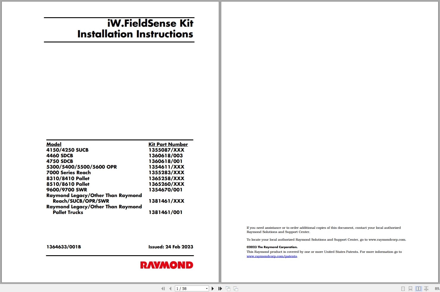
REALEASE :
REALEASE :
-
RAYMON Forklift Technical Publication Library 2015 DVD NEW VERSION
Original price was: 300.150Current price is: 150. USDRAYMON Forklift Technical Publication Library 2015 DVDSize: 4,0Gb PackFormat: PDF, JavaLanguage: EnglishBrand: RAYMONType of machine: RAYMON ForkliftAmount of DVD: 1 DVD rarVersion 5.2.49Type of document:Technical Publication LibraryService Manual (Including in Maintenance Manual)Maintenance ManualParts ManualSchematics ManualYear: 2013-2015Hot-50%
REALEASE :
08.04.2020
REALEASE :
08.04.2020
-
Raymond iW.RTLS Installation Maintenance Manuals
20 USDSize: 12.02 MBFormat: PDFLanguage: EnglishBrand: RaymondType of Machine: iWAREHOUSE RTLSType of Manual: Installation Manual, Maintenance Manual, Electrical SChematic
REALEASE :
REALEASE :
-
RAYMOND Forklift Service Parts Manual Schematics 2020
Original price was: 300.110Current price is: 110. USDThis is a service information package, you will need to use this to repair a vehicleHot-63%
REALEASE :
REALEASE :
-
Raymond iW Essential Schematic Installation Manuals
20 USDSize: 47.24 MBFormat: PDFLanguage: EnglishBrand: RaymondType of Machine: iWAREHOUSE EssentialType of Manual: Installation Manual, Electrical Schematic
REALEASE :
REALEASE :
-
Raymond iPort Kit Installation and Maintenance Manual 1089339001H 2019
20 USDSize: 6.54 MBFormat: PDFLanguage: EnglishBrand: RaymondType of Machine: iPortType of Manual: Maintenance Manual, Kit Installation ManualApplicable Model:4100, 4150, 4200, 4250, 4750 Counterbalanced5400, 5500, 5600 Orderpicker7200, 7300, 7310, 7400, 7420, 7440, 7500, 7520, 7600, 7620, 7640, 7700, 7720 Reach Trucks9600, 9700 Swing-Reach Trucks8300, 8310, 8400, 8410, 8500, 8510, 8720, 8900 Pallet Trucks8600, 8610 Tow TractorsPart Number: 1089339001HPublication Date: 2019Number of Pages: 132 Pages
REALEASE :
REALEASE :
-
Raymond iW.ObjectSense Installation Maintenance Manuals
20 USDSize: 22.14 MBFormat: PDFLanguage: EnglishBrand: RaymondType of Machine: iWAREHOUSE ObjectSenseType of Manual: Installation Manual, Maintenance Manual
REALEASE :
REALEASE :
-
Raymond ZaP Installation Maintenance User Manuals
20 USDSize: 11.39 MBFormat: PDFLanguage: EnglishBrand: RaymondType of Machine: Zoning and Positioning System KitType of Manual: Installation Manual, Maintenance Manual, User Manual
REALEASE :
REALEASE :