
0 ITEMSVIEW CART

✓
Expert Support
✓
Full Speed
✓
100% Working
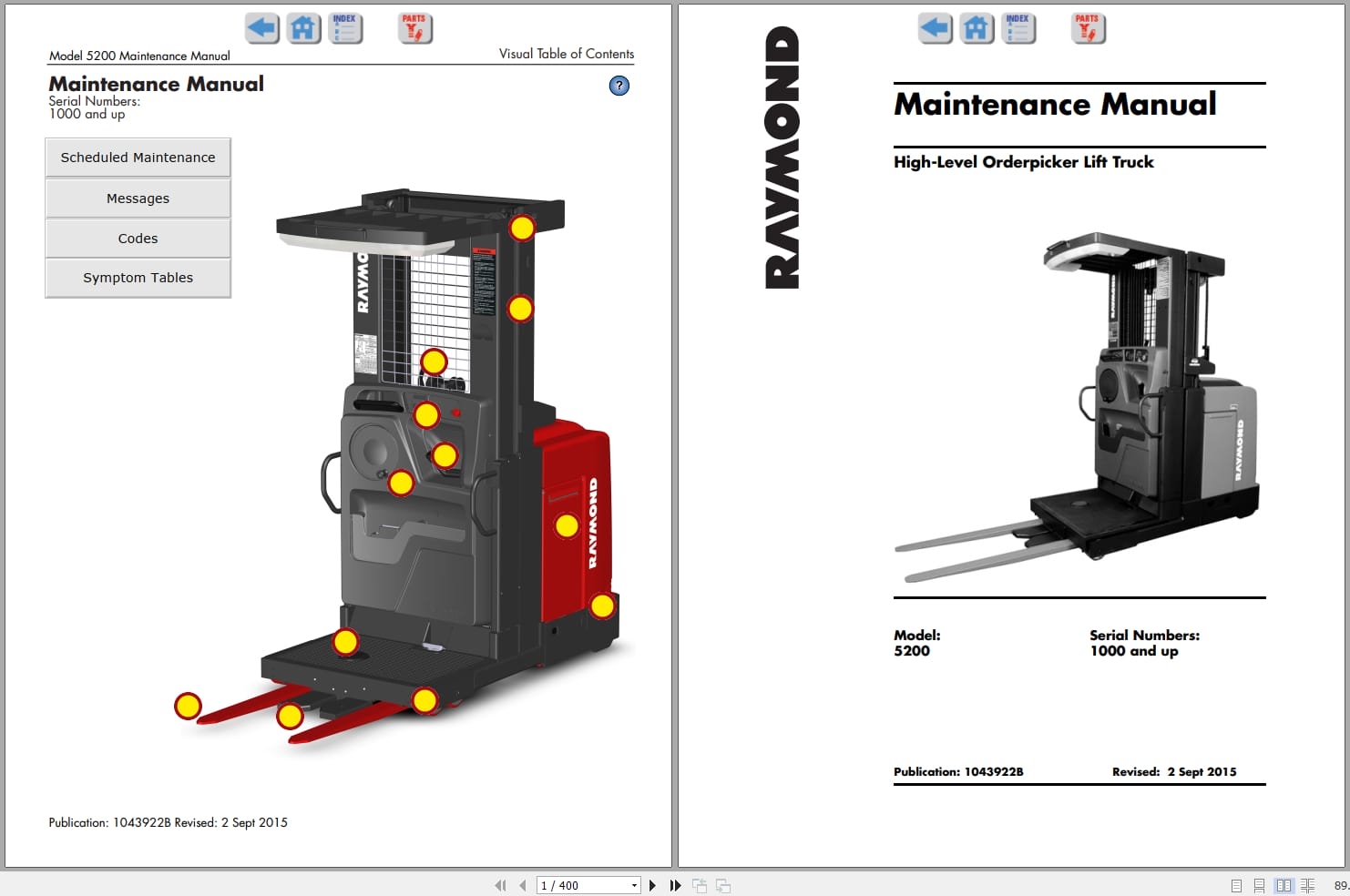
Raymond Orderpicker 5200 Maintenance Manual 1043922B 2015
Size: 28.84 MB
Format: PDF
Language: English
Brand: Raymond
Type of Machine: High-Level Orderpicker Lift Truck
Type of Manual: Maintenance Manual, Electrical Schematic
Model: Raymond 5200 High-Level Orderpicker Lift Truck
Serial Number: 1000 and up
Part Number: 1043922B
Publication Date: 2015
Number of Pages: 400 Pages
20 USD
- Description
Description
Contents:
Visual Table of Contents
Cover Page
Table of Contents
Document Revision History
Service Information List
Section 1. How to Use This Manual
Manual Design
Interactive Electronic Technical Manuals
Abbreviations and Symbols
Section 2. Safety
Definitions
General Safety
Battery Safety
Static Precautions
Jacking Safety
Emergency Lower Valve
Tie-Down for Transport
Towing
Welding Safety
Section 3. Systems Overview
Introduction
Lift Truck Specifications
General Information
Installation
Wire Guidance
Wire Guidance Setup Procedure
FlashWare
Cold Storage
UL Label “EEâ€
Section 4. Scheduled Maintenance
Maintenance Guidelines
Initial 90 Day/250 Deadman Hours (HD) Maintenance
Every 180 Days or 500 Deadman Hours (HD)
Every 360 Days or 2000 Deadman Hours (HD)
Contactor Tip Inspection
Chain Maintenance
Section 5. Troubleshooting
Electrical Troubleshooting
Troubleshooting Wiring Problems
Switches (General)
Electric Motor Tests
Contactors
Fuses
Wire Guidance Troubleshooting
Wire Guidance Troubleshooting in FlashWare
Hydraulic Troubleshooting Guidelines
Definitions
Electrical Connector Locator Chart
Programmable Maintenance Tool
Drive Unit Troubleshooting Guide
List of Troubleshooting Tables
Symptom Tables: Hydraulic Functions
Symptom Tables: Travel Functions
Symptom Tables: Electrical Symptoms
Section 6. Messages, Codes, and Tests
Operator Display Messages
Maintenance Mode
Traction Power Amplifier Fault Codes
Guidance Manager Operational Codes
Guidance Manager Fault Codes
Tests
Operator Display Fault Codes
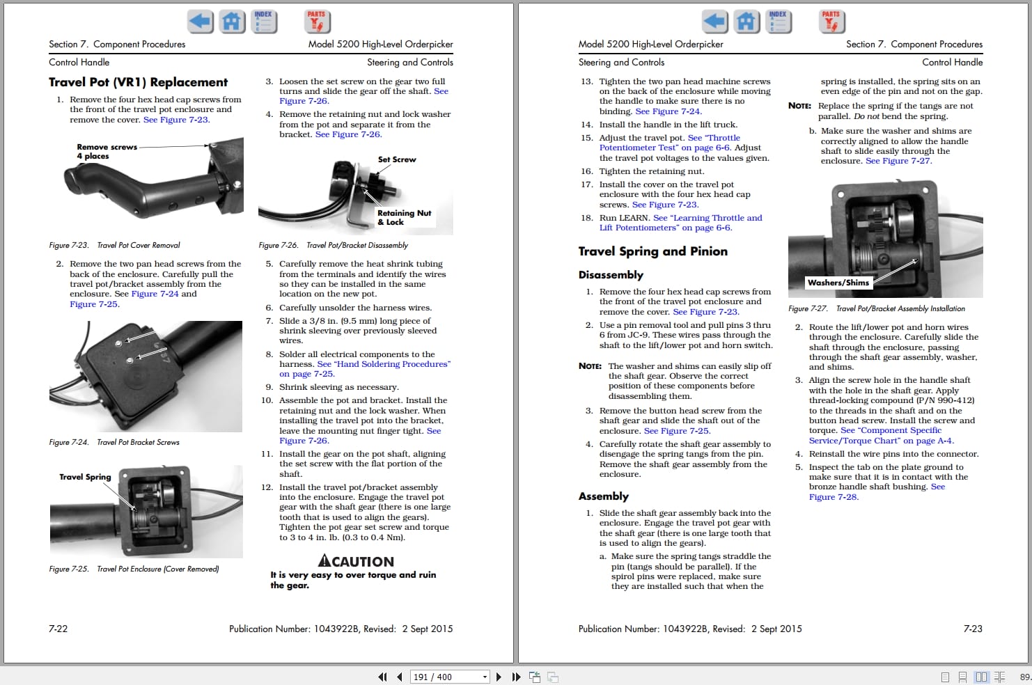
Section 7. Component Procedures
List of Component Procedures
Component locator Photos
Covers and Finish
Special Tools and Decals
Steering and Controls
Drive and Brake
Electrical Components
Hydraulic Components
Mast Section
Section 8. Theory of Operation
Battery Plugged In
Key Switch (S1) ON
Closing Deadman Switches
Travel
Steering
Lift/Lower
Primary Memory
Wire Guidance System
Pinout Matrix
Section A. Appendix
Lubrication Specification Chart
Thread Adhesives, Sealants, and Lubricants
Component Specific Service/Torque Chart
Torque Chart – Hydraulic Fittings
Torque Chart – Straight Thread Face Seal O-Rings
Torque Chart – Standard (Ferrous)
Torque Chart – Metric (Ferrous)
Torque Chart – Standard (Brass)
Torque Chart – Metric (Brass)
Torque Chart – Thread Forming Screws
Decimal Equivalent Chart
Standard/Metric Conversions
Index
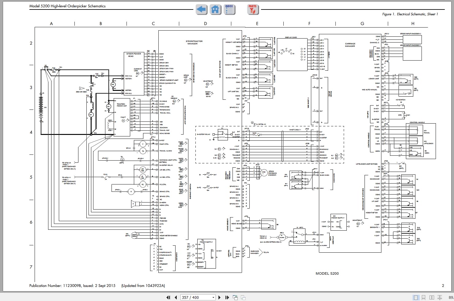
Schematics
Figure 1. Electrical Schematic, Sheet 1
Figure 2. Electrical Schematic, Sheet 2
Figure 3. Electrical Schematic, Legend
Figure 4. Hydraulic Schematic
RSIs
Electrical Interference with Radio Frequency
Scheduled Maintenance – Software Updates
Battery Power/Communication Cable Lead Lengths and Housekeeping
New Battery Spacer Kits Available
Model 5200 Code 4,2 missing information
FlashWare 8.0 Functionality and Enhancements
Deadman Pedal Switch Replacement
Updated Deadman Pedal
5200 Mast Cables
Scheduled Maintenance Changes
Elimination of 90 Day Inspection
New Steer Tractor Manager Circuit Card
Switch Replacement
New Horn Available
New Free Lift Cylinder Piston Plunger
New Steering Encoder
Control Handle Fault Codes
New Pump Spline Lubricant
Electrical Troubleshooting
Related Products
-
Raymond iW Essential Schematic Installation Manuals
20 USDSize: 47.24 MBFormat: PDFLanguage: EnglishBrand: RaymondType of Machine: iWAREHOUSE EssentialType of Manual: Installation Manual, Electrical Schematic
REALEASE :
REALEASE :
-
Raymond iW.RTLS Installation Maintenance Manuals
20 USDSize: 12.02 MBFormat: PDFLanguage: EnglishBrand: RaymondType of Machine: iWAREHOUSE RTLSType of Manual: Installation Manual, Maintenance Manual, Electrical SChematic
REALEASE :
REALEASE :
-
RAYMOND Forklift Service Parts Manual Schematics 2020
Original price was: 300.110Current price is: 110. USDThis is a service information package, you will need to use this to repair a vehicleHot-63%
REALEASE :
REALEASE :
-
RAYMON Forklift Technical Publication Library 2015 DVD NEW VERSION
Original price was: 300.150Current price is: 150. USDRAYMON Forklift Technical Publication Library 2015 DVDSize: 4,0Gb PackFormat: PDF, JavaLanguage: EnglishBrand: RAYMONType of machine: RAYMON ForkliftAmount of DVD: 1 DVD rarVersion 5.2.49Type of document:Technical Publication LibraryService Manual (Including in Maintenance Manual)Maintenance ManualParts ManualSchematics ManualYear: 2013-2015Hot-50%
REALEASE :
08.04.2020
REALEASE :
08.04.2020
-
Raymond iPort Kit Installation and Maintenance Manual 1089339001H 2019
20 USDSize: 6.54 MBFormat: PDFLanguage: EnglishBrand: RaymondType of Machine: iPortType of Manual: Maintenance Manual, Kit Installation ManualApplicable Model:4100, 4150, 4200, 4250, 4750 Counterbalanced5400, 5500, 5600 Orderpicker7200, 7300, 7310, 7400, 7420, 7440, 7500, 7520, 7600, 7620, 7640, 7700, 7720 Reach Trucks9600, 9700 Swing-Reach Trucks8300, 8310, 8400, 8410, 8500, 8510, 8720, 8900 Pallet Trucks8600, 8610 Tow TractorsPart Number: 1089339001HPublication Date: 2019Number of Pages: 132 Pages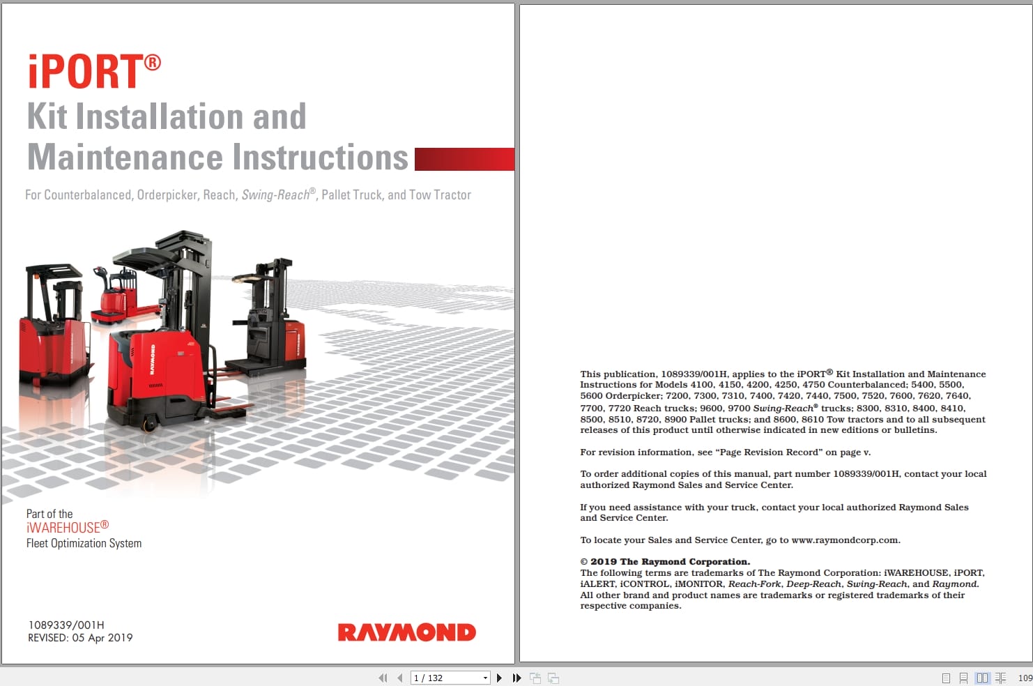
REALEASE :
REALEASE :
-
Raymond iW.ObjectSense Installation Maintenance Manuals
20 USDSize: 22.14 MBFormat: PDFLanguage: EnglishBrand: RaymondType of Machine: iWAREHOUSE ObjectSenseType of Manual: Installation Manual, Maintenance Manual
REALEASE :
REALEASE :
-
Raymond iW Evolution Installation Maintenance User Guide Manuals
20 USDSize: 106.70 MBFormat: PDFLanguage: EnglishBrand: RaymondType of Machine: iWAREHOUSEType of Manual: Installation Manual, Maintenance Manual, User Manual, Electrical Schematic
REALEASE :
REALEASE :
-
Raymond iWH iW.FieldSense Installation User Guide Manuals
20 USDSize: 15.88 MBFormat: PDFLanguage: EnglishBrand: RaymondType of Machine: iWAREHOUSE iW.FieldSenseBType of Manual: Installation Manual, User Manual
REALEASE :
REALEASE :