
20 ITEMSVIEW CART


Total: 3,645.00$
Expert Support
Full Speed
100% Working
30$ USD
Contents:
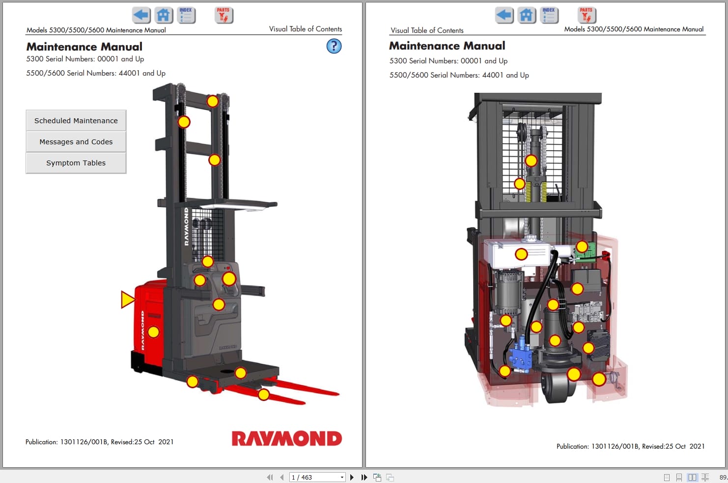
Section 1. How to Use This Manual
Manual Design
Interactive Electronic Technical Manuals
Abbreviations and Symbols
Section 2. Safety
Definitions
General Safety
Battery Safety
Static Precautions
Jacking Safety
Emergency Lower Valve
Tie-Down for Transport
Towing
Welding Safety
Section 3. Systems Overview
Introduction
Lift Truck Specifications
General Information
Installation
Operator Display
Modes of Operation
FlashWare
Wire Guidance
Cold Storage
Storage
UL Label “EEâ€
Section 4. Scheduled Maintenance
Maintenance Guidelines
Maintenance Minder â„¢ Tool
Initial 90 Day/250 Deadman Hours (HD) Maintenance
Every 180 Days or 500 Deadman Hours (HD)
Every 360 Days or 2000 Deadman Hours (HD)
Chain Maintenance
Contactor Tip Inspection
Section 5. Troubleshooting
Electrical Troubleshooting
Drive Unit Troubleshooting
Troubleshooting Aisle Exit Error Code J2
Symptom Tables: Hydraulic Functions
Symptom Tables: Travel Functions
Symptom Tables: Electrical Symptoms
Section 6. Messages, Codes, and Tests
Power Amp LED Diagnostics
Summary List
Messages and Codes
Analog Input Tests
Input Tests
Output Tests
Component Locator Photos
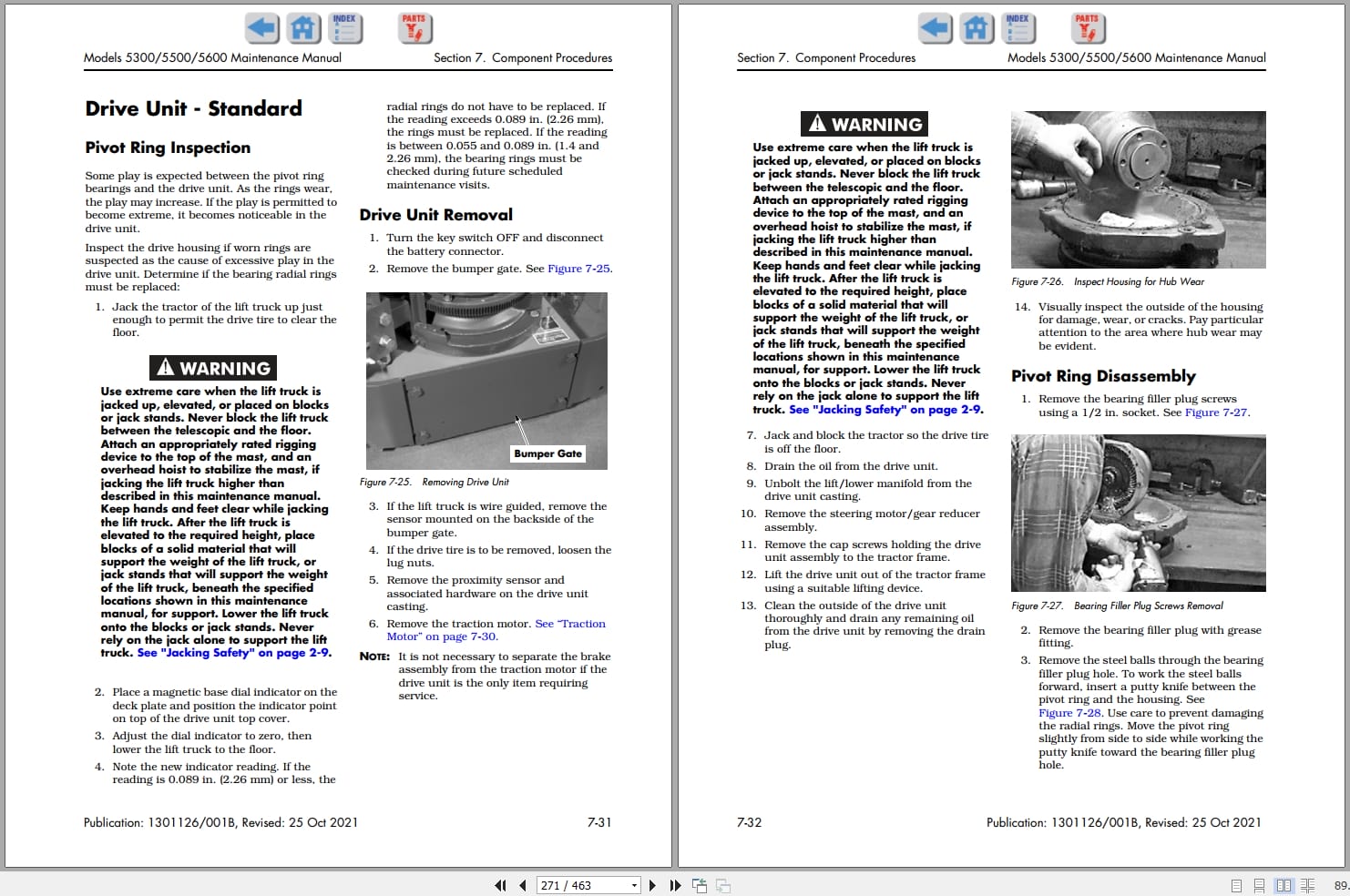
Section 7. Component Procedures
List of Component Procedures
Special Tools and Decals
Steering and Controls
Drive and Brake
Electrical Components
Hydraulic Components
Mast Section
Section 8. Theory of Operation
System Architecture
Traction System
Steering System
Lift/Lower System
Wire Guidance System
Pin-Out Matrix
Section A. Appendix
Lubrication Specification Chart
Thread Adhesives, Sealants, and Lubricants
Component Specific Service/Torque Chart
Torque Chart – Hydraulic Fittings
Torque Chart – Straight Thread Face Seal O-Rings
Torque Chart – Standard (Ferrous)
Torque Chart – Metric (Ferrous)
Torque Chart – Standard (Brass)
Torque Chart – Metric (Brass)
Torque Chart – Thread-Forming Screws
Decimal Equivalent Chart
Standard/Metric Conversions
Index
Index
Schematics
Figure 1. Power Distribution Diagram Sheet 1 (DC Lift)
Figure 2. Power Distribution Diagram Sheet 2 (AC Lift)
Figure 3. Electrical Schematic Sheet 1 (AC Lift)
Figure 4. Electrical Schematic Sheet 2 (DC Lift)
Figure 5. Electrical Schematic Sheet 3
Figure 6. Electrical Schematic Sheet 4
Figure 7. Electrical Schematic Sheet 5
Figure 8. Electrical Schematic Sheet 6, iWarehouse
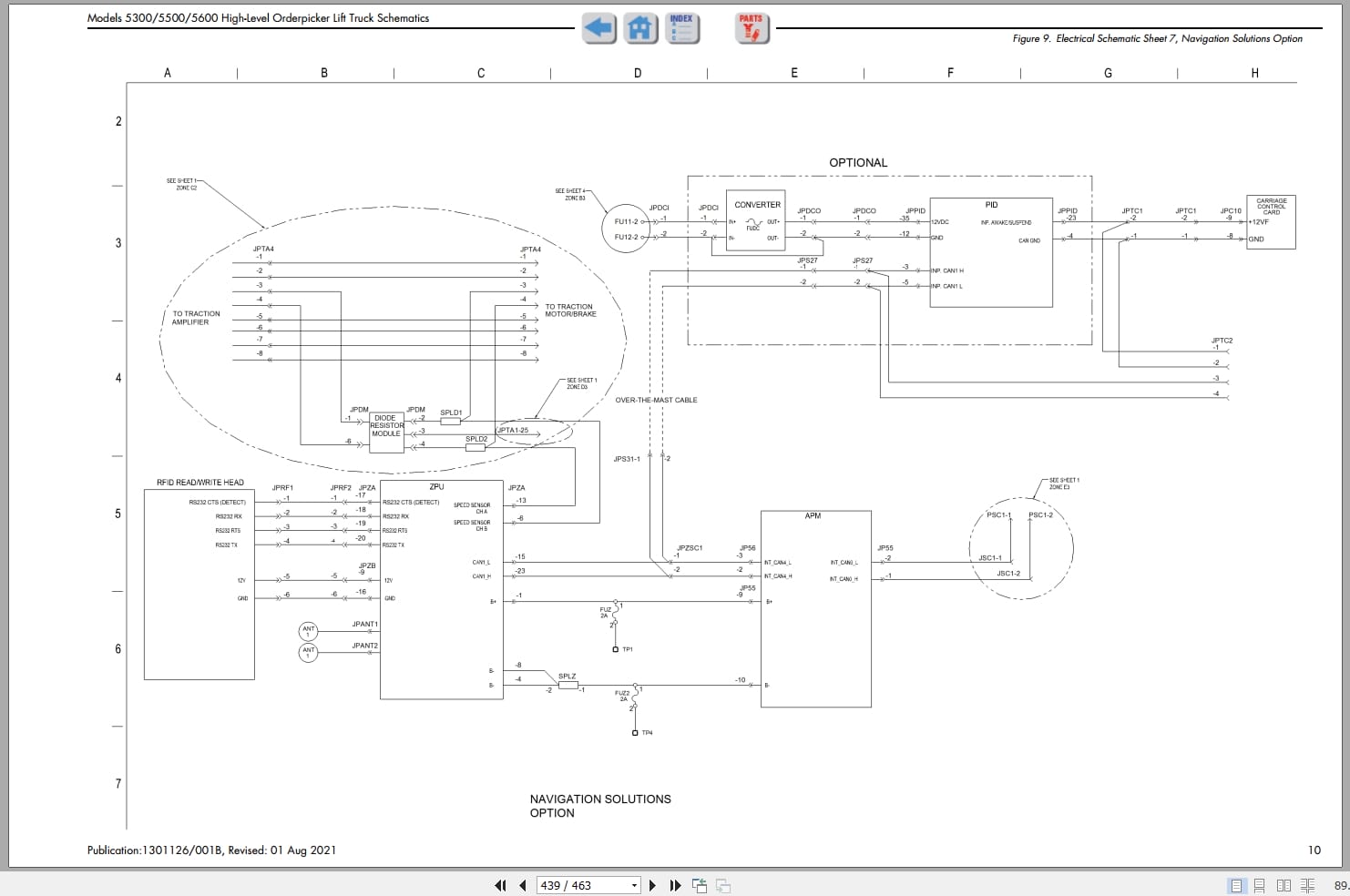
Figure 9. Electrical Schematic Sheet 7, Navigation Solutions Option
Figure 10. Electrical Schematic Sheet 8, Legend
Figure 11. Hydraulic Schematic, Standard Lift 5500/5600
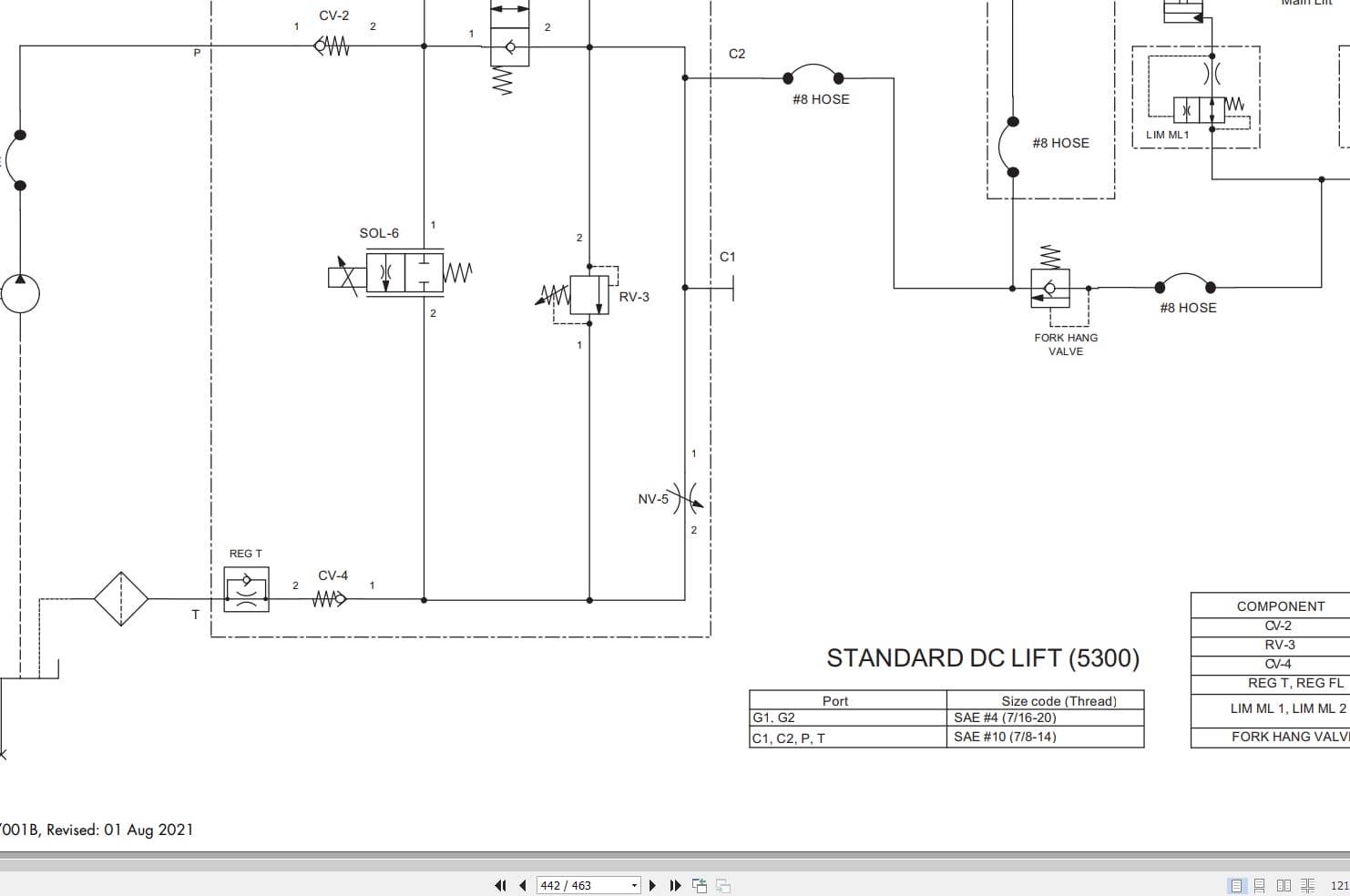
Figure 12. Hydraulic Schematic, Standard Lift 5300
Figure 13. Hydraulic Schematic, Auxiliary Lift (5600)
RSIs
High Capacity Orderpicker Procedures – Articulating Load Wheel Replacement,
Forward Tilt and Lateral Lean Inspection, Mast Brace Procedure
Manifold Noise When Lifting/Lowering
Electrical Interference with Radio Frequency
Scheduled Maintenance – Software Updates
Battery Power/Communication Cable Lead Lengths and Housekeeping
F-Series Power Amplifiers
New Vehicle Manager (VM) Software Version 1.30
Brake Harness Adjustment
REALEASE :
REALEASE :

REALEASE :
08.04.2020
REALEASE :
08.04.2020
REALEASE :
REALEASE :
REALEASE :
REALEASE :
REALEASE :
REALEASE :
REALEASE :
REALEASE :
REALEASE :
REALEASE :

REALEASE :
REALEASE :
 Automotive - Heavy Equipment - Truck & Bus - Forklift - Crane