
15 ITEMSVIEW CART


Total: 1,297.00
Expert Support
Full Speed
100% Working
20 USD
Contents:
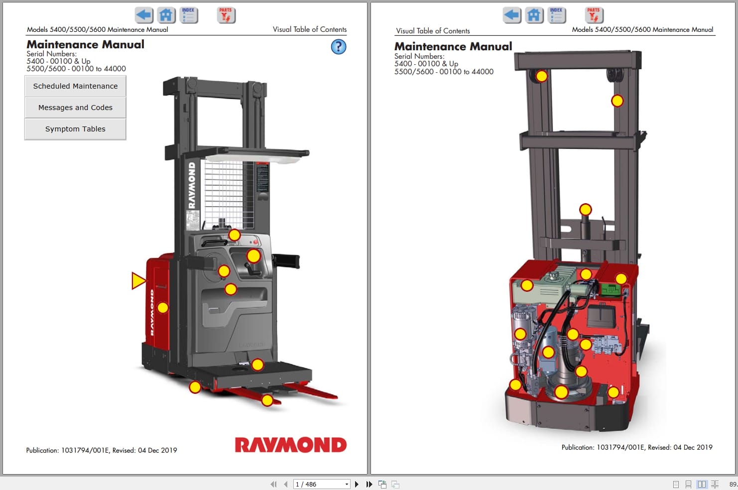
Section 1. How to Use This Manual
Manual Design
Interactive Electronic Technical Manuals
Abbreviations and Symbols
Section 2. Safety
Definitions
General Safety
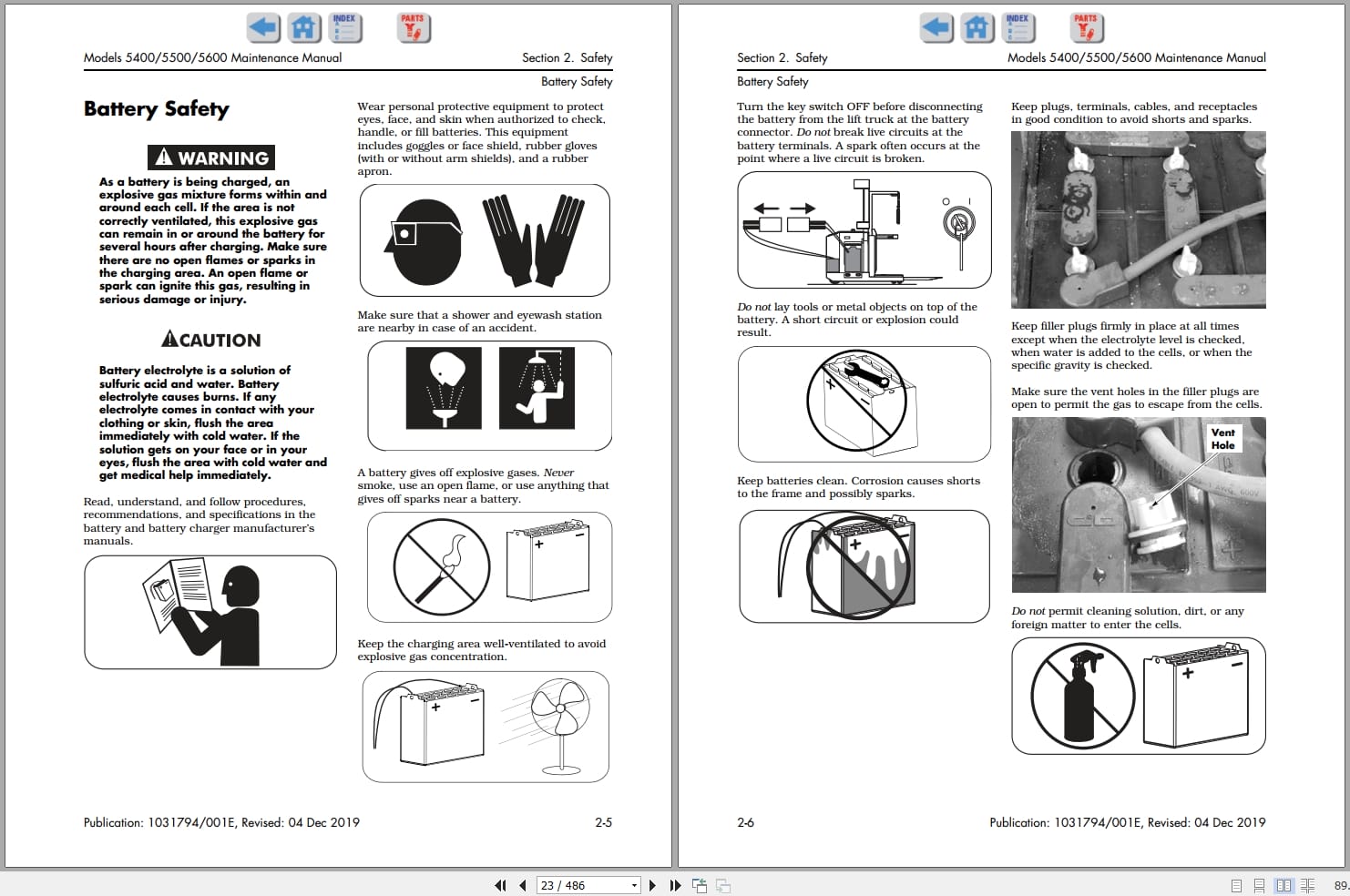
Battery Safety
Static Precautions
Jacking
Emergency Lower Valve
Tie-Down for Transport
Towing
Welding Safety
Section 3. Systems Overview
Introduction
Lift Truck Specifications
General Information
Installation
Operator Display
Modes of Operation
FlashWare
Wire Guidance
Cold Storage
Storage
UL Label “EEâ€
Section 4. Scheduled Maintenance
Maintenance Guidelines
Maintenance Minder â„¢ Tool
Initial 90 Day/250 Deadman Hours (HD) Maintenance
Every 180 Days or 500 Deadman Hours (HD)
Every 360 Days or 2000 Deadman Hours (HD)
Chain Maintenance
Contactor Tip Inspection
Section 5. Troubleshooting
Electrical Troubleshooting
Drive Unit Troubleshooting
Communication Error Code (50 Series) Troubleshooting
Troubleshooting Aisle Exit Error Code J2
Symptom Tables: Hydraulic Functions
Symptom Tables: Travel Functions
Symptom Tables: Electrical Symptoms
Section 6. Messages, Codes, and Tests
Power Amp LED Diagnostics
Summary List
Messages and Codes
Analog Input Tests
Test A04 – Throttle Potentiometer Voltage
Test A05 – Lift/Lower Potentiometer Voltage
Test A08 – Traction Motor Temperature
Test A09 – Lift Motor Temperature
Test A10 – Traction Power Amplifier Temperature
Test A11 – Traction Motor Current
Test A13 – Pressure Sensor Voltage (optional)
Test A14 – VM +12V Power Supply
Test A15 – Battery Voltage
Test A19 – Lift Power Amplifier Temperature (AC lift only)
Test A20 – Lift Motor Current (AC lift only)
Test A22 – Traction Throttle Request
Test A23 – Lift Request
Test A34 – Lift/Lower Current
Test A35 – Brake
Test A37 – Steer Power Amplifier Current
Test A51 – Left Tractor Guidance Coil Voltage
Test A52 – Right Tractor Guidance Coil Voltage
Test A53 – Left Load Guidance Coil Voltage
Test A54 – Right Load Guidance Coil Voltage
Test A55 – Tractor Near Wire Coil Voltage
Test A56 – Load Near Wire Coil Voltage
Tests A96 through A100 – iBATTERY Tests
Test A101 – Guidance Manager 12V Power Supply Out of Range
Input Tests
Test I00 – Carriage Deadman
Test I01 – Brake Deadman Switch (S2)
Test I02 – Lower Mast Reference (24 in.) Switch
Test I03 – 60 in. Limit Switch
Test I04 – Lift/Lower Inhibit Bypass (optional)
Test I05 – Lift Inhibit Switch (optional)
Test I15 – Horn Switch
Test I19 – Traction Motor RPM
Test I20 – Lift Motor RPM (AC lift only)
Test I23 – CAN Bus
Test I24 – Home Position Proximity Sensor
Test I25 – Steer Motor Encoder
Test I26 – Flow Sensor Count
Test I35 – Steer Tiller Encoder 1
Test I36 – Steer Tiller Encoder 2
Test I38 – EPO Switch
Test I39 – Neutral Pulses
Test I41 – Aux Mast Lift Switch S32 (CCC 1107833/101)
Test I41 – Aux Mast Lift Switch S32 (CCC 1275051/003)
Test I42 – Aux Mast Lower Switch S33 (CCC 1107833/101)
Test I42 – Aux Mast Lower Switch S33 (CCC 1275051/003)
Test I43 – Slack Chain Switch (CCC1107833/101)
Test I43 – Slack Chain Switch (CCC 1275051/003)
Test I44 – Aux Mast Lift Ref Switch S34 (CCC 1107833/101)
Test I44 – Aux Mast Lift Ref Switch S34 (CCC 1275051/003)
Test I45 – Slk S29 [Slack Chain 1 Switch (S29)]
Test I46 – Slk Ch S30 [Slack Chain 2 Switch (S30)]
Test I65 – Rail Guidance Switch (optional)
Test I66 – Auto/Manual Switch (optional)
Test I67 – Sidegate Switches (optional)
Test I68 – Travel Cutout/Battery Gate and PSL Switch (optional)
Test I69 – Upper Mast Reference Switch
Test I70 – Pressure Switch (optional)
Test I72 – End-of-Aisle Sensor 2 (optional)
Test I73 – End-of-Aisle Sensor 1 (optional) – Software versions 5.7 and below
Test I73 – EOA2, Left – Software versions 5.8 and above
Test I74 – Lower Inhibit Switch (optional)
Test I75 – 180 in. Limit Switch (optional)
Test I76 – Lift Cutout Switch (optional)
Test I91 – iPORT Communication
Test I92 – iPORT Error Bitmap
Test I93 – End Of Aisle EOA
Output Tests
Test O00 – Toggle the Traction Power Contactor
Test O02 – Toggle the Lift Power Contactor
Test O11 – Toggle Load Holding Solenoid
Test O12 – Proportional Solenoid PWM Ramp
Test O18 – Toggle Horn
Test O19 – Audible Alarm
Test O20 – Travel Alarm (optional)
Test O25 – Toggle 2 Stage Select Solenoid (optional)
Test O28 – Ramp Lift Motor (AC lift only)
Test O29 – Ramp Traction Motor
Test O30 – Toggle Brake Solenoid
Test O32 – Toggle Relay Enable
Test O39 – Display Lights
Test O40 – Lift/Lower Alarm (optional)
Test O41 – Aux Select Solenoid (optional)
Test O42 – Main Select Solenoid (optional)
Test O43 – Aux Load Hold Solenoid (optional)
Test O44 – Steer Motor
Section 7. Component Procedures
List of Component Procedures
Component Locator Photos
Special Tools and Decals
Steering and Controls
Drive and Brake
Electrical Components
Hydraulic Components
Mast Section
Section 8. Theory of Operation
System Architecture
Traction System
Steering System
Lift/Lower System
Wire Guidance System
Pin-Out Matrix
Section A. Appendix
Lubrication Specification Chart
Thread Adhesives, Sealants, and Lubricants
Component Specific Service/Torque Chart
Torque Chart – Hydraulic Fittings
Torque Chart – Straight Thread Face Seal O-Rings
Torque Chart – Standard (Ferrous)
Torque Chart – Metric (Ferrous)
Torque Chart – Standard (Brass)
Torque Chart – Metric (Brass)
Torque Chart – Thread-Forming Screws
Decimal Equivalent Chart
Standard/Metric Conversions
Index
Schematics
Figure 1. Power Distribution Diagram Sheet 1 (AC Lift)
Figure 2. Power Distribution Diagram Sheet 2 (DC Lift)
Figure 3. Electrical Schematic Sheet 1 (AC Lift)
Figure 4. Electrical Schematic Sheet 2 (DC Lift)
Figure 5. Electrical Schematic Sheet 3
Figure 6. Electrical Schematic Sheet 4
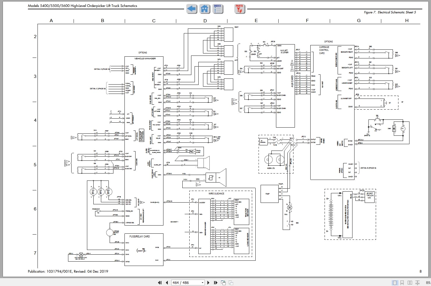
Figure 7. Electrical Schematic Sheet 5
Figure 8. Electrical Schematic Sheet 6
Figure 9. Electrical Schematic Sheet 7
Figure 10. Electrical Schematic Legend
Figure 11. Hydraulic Schematic, Single Speed Lift
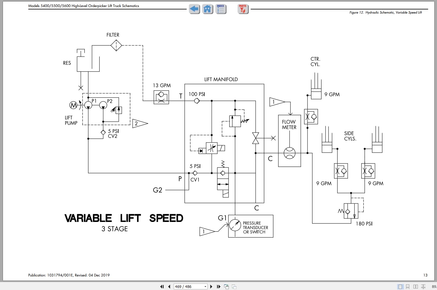
Figure 12. Hydraulic Schematic, Variable Speed Lift
Figure 13. Hydraulic Schematic, Variable Speed Lift with Auxiliary Lift
RSIs
Electrical Interference with Radio Frequency
Scheduled Maintenance – Software Updates
Battery Power/Communication Cable Lead Lengths and Housekeeping
Brake Harness Adjustment
“Release Buttons†message
New Battery Spacer Kits Available
New Software Release VM version 9.9
Revisions to Test A04 and A05
Main Wiring Harness Changes
REALEASE :
REALEASE :
REALEASE :
REALEASE :
REALEASE :
REALEASE :
REALEASE :
REALEASE :

REALEASE :
08.04.2020
REALEASE :
08.04.2020
REALEASE :
REALEASE :

REALEASE :
REALEASE :
REALEASE :
REALEASE :
 Automotive - Heavy Equipment - Truck & Bus - Forklift - Crane