
0 ITEMSVIEW CART


✓
Expert Support
✓
Full Speed
✓
100% Working
Raymond Pallet Truck 8210 Maintenance Manual 1369527001B 2023
Size: 11.68 MB
Format: PDF
Language: English
Brand: Raymond
Type of Machine: Pallet Truck
Type of Manual: Maintenance Manual, Electrical Schematic
Model: Raymond 8210 Pallet Truck
Serial Number: 821-15-00100 & Up
Part Number: 1369527001B
Publication Date: 2023
Number of Pages: 324 Pages
40 USD
- Description
Description
Contents:
Section 1. How To Use This Manual
Manual Design
Interactive Electronic Technical Manuals
Abbreviations & Symbols
Section 2. Safety
Safety Definitions
General Safety
Lead Acid Battery Safety
Jacking Safety
Towing
Tie-Down for Transport
Static Precautions
Welding Safety
Section 3. Systems Overview
Introduction
Lift Truck Model Identification
Lift Truck Specifications
Special Tools
Operator Display and Programming
Display Part Numbers (Pn)
Display Test (d)
Service Input/Output Display
FlashWare
Section 4. Scheduled Maintenance
Scheduled Maintenance Guidelines
Initial 90 Day/250 Deadman Hours (HD) Maintenance
Every 180 Days or 500 Deadman Hours (HD)
Every 360 Days or 2000 Deadman Hours (HD)
Wash-down Procedure
Grease Fittings
Pin Locations
Section 5. Troubleshooting
List of Troubleshooting Charts and Tables
Electrical Troubleshooting Guidelines
DC Electric Motors
AC Electric Motors
Coil Theory (F-Series Controller Only)
Hydraulic Troubleshooting Guidelines
Symptom Tables: Electrical System
Symptom Tables: Lift/Lower System
Symptom Tables: Travel (Forward/Reverse) System
Charger Troubleshooting
Section 6. Messages and Codes
List of Messages and Codes
Messages and Caution Codes
Error Codes
Traction Amplifier Flash Codes
Delta-Q Charger Codes
Section 7. Component Procedures
List of Component Procedures by Component System
Component Location Photos
Finish and Accessories
Steering and Controls
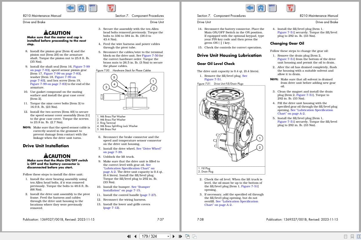
Drive and Brake
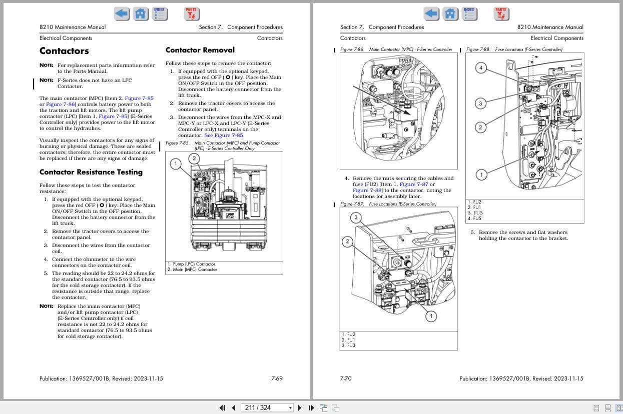
Electrical Components
Hydraulic Components
Mast
Options
Section 8. Theory of Operation
Definitions
Lift Truck Starting
Traction System
Lift/Lower System
Pinout Matrix
Section A. Appendix
Lubrication Specification Chart
Thread Adhesives, Sealants, and Lubricants
Component Specific Service/Torque Chart
Torque Chart – Standard (Ferrous)
Torque Chart – Standard (Brass)
Torque Chart – Metric (Ferrous)
Torque Chart – Metric (Brass)
Torque Chart – Thread Forming Screws
Torque Chart – Hydraulic Fittings
Torque Chart – Straight Thread Face Seal O-Rings
Decimal Equivalent Chart
Standard/Metric Conversions
Section I. Index
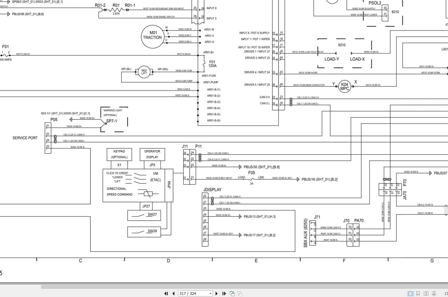
Schematics
Figure 1. 8210 Electrical Schematic – E-Series Controller
Figure 2. 8210 Options – E-Series Controller
Figure 3. 8210 Component Legend – E-Series Controller
Figure 4. 8210 Electrical Schematic – F-Series Controller
Figure 5. 8210 Component Legend – F-Series Controller
Figure 6. 8210 Option – Pallet Handle/Tiller – F-Series Controller
Figure 7. 8210 Option – Handle Second CAN Bus – F-Series Controller
Figure 8. 8210 Option – Accessory Bar – F-Series Controller
Figure 9. 8210 Hydraulic Schematic
RSIs
Class III Accessory Bar
New Service Key Required for F-Series Amplifiers
Related Products
-
Raymond iW Essential Schematic Installation Manuals
20 USDSize: 47.24 MBFormat: PDFLanguage: EnglishBrand: RaymondType of Machine: iWAREHOUSE EssentialType of Manual: Installation Manual, Electrical Schematic
REALEASE :
REALEASE :
-
Raymond Forklift 4760 Maintenance Manual 1451076_001A
80 USDSize: 123.87 MBFormat: PDFLanguage: EnglishBrand: RaymondType of Machine: ForkliftType of Manual: Maintenance Manual, Electric DiagramModel: Raymond4760-C404760-C40S4760-C504760-C50S4760-C50L4760-C554760-C604760-C654760-C65LSerial Numbers: 00001 and UpPart Number: 1451076/001APublication Date: 2025Number of Pages: 1626 Pages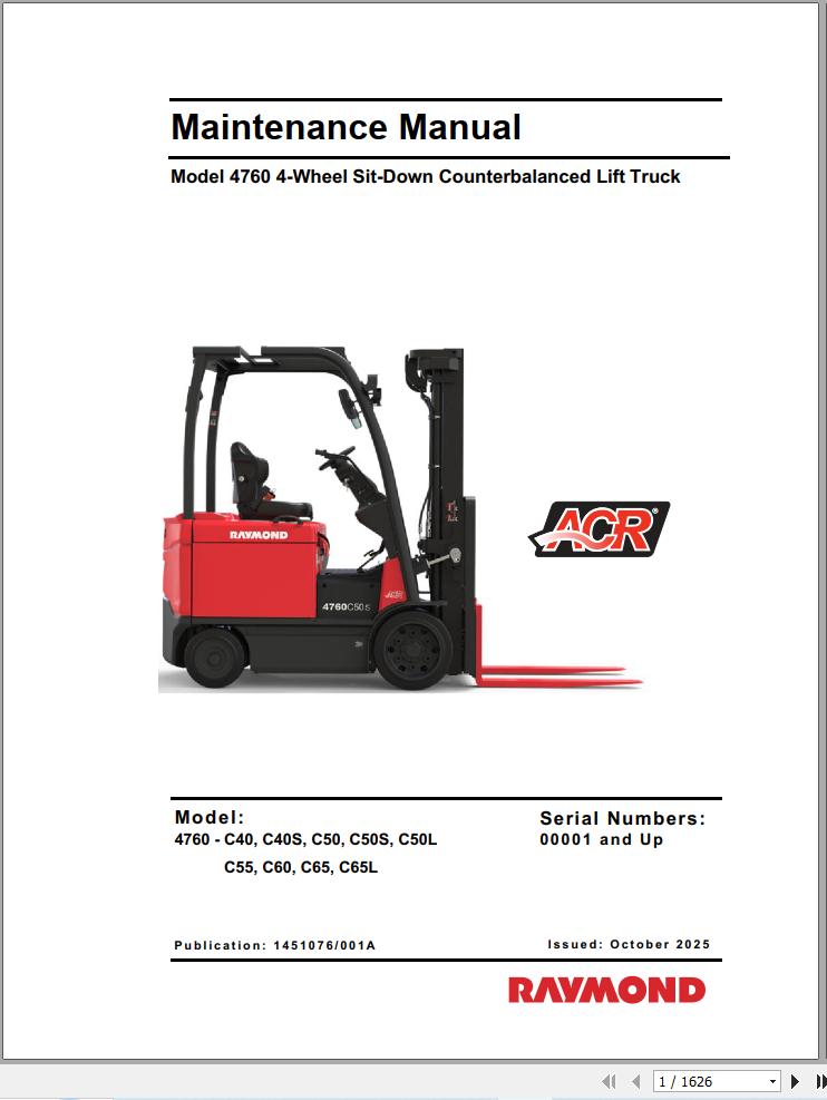
REALEASE :
REALEASE :
-
RAYMON Forklift Technical Publication Library 2015 DVD NEW VERSION
Original price was: 300.150Current price is: 150. USDRAYMON Forklift Technical Publication Library 2015 DVDSize: 4,0Gb PackFormat: PDF, JavaLanguage: EnglishBrand: RAYMONType of machine: RAYMON ForkliftAmount of DVD: 1 DVD rarVersion 5.2.49Type of document:Technical Publication LibraryService Manual (Including in Maintenance Manual)Maintenance ManualParts ManualSchematics ManualYear: 2013-2015Hot-50%
REALEASE :
08.04.2020
REALEASE :
08.04.2020
-
RAYMOND Forklift Service Parts Manual Schematics 2020
Original price was: 300.110Current price is: 110. USDThis is a service information package, you will need to use this to repair a vehicleHot-63%
REALEASE :
REALEASE :
-
Raymond iW.ObjectSense Installation Maintenance Manuals
20 USDSize: 22.14 MBFormat: PDFLanguage: EnglishBrand: RaymondType of Machine: iWAREHOUSE ObjectSenseType of Manual: Installation Manual, Maintenance Manual
REALEASE :
REALEASE :
-
Raymond iW Evolution Installation Maintenance User Guide Manuals
20 USDSize: 106.70 MBFormat: PDFLanguage: EnglishBrand: RaymondType of Machine: iWAREHOUSEType of Manual: Installation Manual, Maintenance Manual, User Manual, Electrical Schematic
REALEASE :
REALEASE :
-
Raymond iWH iW.FieldSense Installation User Guide Manuals
20 USDSize: 15.88 MBFormat: PDFLanguage: EnglishBrand: RaymondType of Machine: iWAREHOUSE iW.FieldSenseBType of Manual: Installation Manual, User Manual
REALEASE :
REALEASE :
-
Raymond iW.RTLS Installation Maintenance Manuals
20 USDSize: 12.02 MBFormat: PDFLanguage: EnglishBrand: RaymondType of Machine: iWAREHOUSE RTLSType of Manual: Installation Manual, Maintenance Manual, Electrical SChematic
REALEASE :
REALEASE :