
0 ITEMSVIEW CART


✓
Expert Support
✓
Full Speed
✓
100% Working
Takeuchi Track Loader TL12R2 Workshop Manual WETL12R_E-XI
Size: 97.63 MB
Format: PDF
Language: English
Brand: Takeuchi
Type of Machine: Track Loader
Type of Manual: Workshop Manual, Electric and Hydraulic Diagrams
Model: Takeuchi TL12R2 Track Loader
Serial Number: 412100002-
Part Number: WETL12R_E-XI
Book Number: CR1E008
Number of Pages: 442 Pages
20 USD
- Description
Description
Contents:
1 SAFETY
Safety alert symbol
Safety precautions
Cautions when working2 SERVICE DATA
Dimensional drawing
Specification tables
Table of masses
Lubricant and fuel chart
Performance criteria
Tightening torque
Hydraulic hose
Bite-type pipe fitting for steel pipe
Joint for piping
Joint for piping (O-ring seal type)
Bolts and nuts (JIS strength category 10.9)
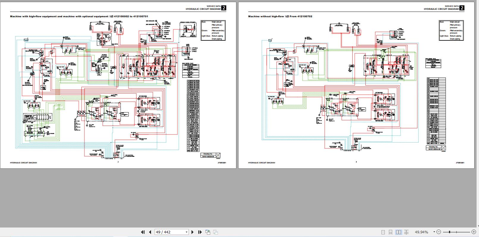
Hydraulic circuit diagram
Machine without high-flow, Serial No.: 412100002 to 412100701
Machine with high-flow equipment and machine with optional equipment, Serial No.: 412100002 to 412100701
Machine without high-flow, Serial No.: From 412100702
Machine with high-flow equipment and machine with optional equipment, Serial No.: From 412100702
Electrical circuit diagram
Hydraulic Device Layout Diagram3 FUNCTION
Gear pump
Sub valve
Pilot valve
Proportional control solenoid valve(active Power control)
Proportional control solenoid valve (1st auxiliary line piping)
Cylinder4 DISASSEMBLY AND ASSEMBLY
Service standards
Drive system
Travel system
Frame
Operating device
Attachments
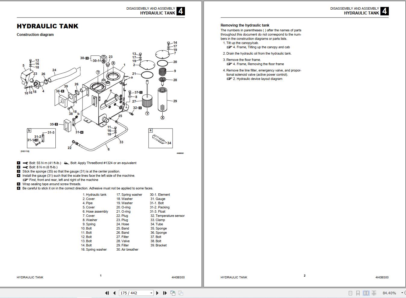
Hydraulic tank
Gear pump
Gear pump (High flow)
Sub valve
Pilot valve
Proportional control solenoid valve(active power control)
Proportional control solenoid valve (1st auxiliary line piping)
Cylinder
Lift arm cylinder
Bucket cylinder (left)
Bucket cylinder (right)
Disassembly and assembly
Tools required
Wire harness
Electrical wiring assembly: 06942-00271-01
GPS Unit Assembly
Battery assembly: 06944-00006-02
Radio assembly: 06947-00004-03
Attachment wiring assembly (machine with mechanical quick-hitch): 06942-00273-00
Attachment wiring assembly (machine with hydraulic quick-hitch): 06942-00281-00
Cabin wiring diagram5 TROUBLESHOOTING
About the troubleshooting section
Overall machine
Traveling
Lift arm
Bucket
Service
Gear pump
Sub valve
Pilot valve
Proportional solenoid valve (active power control, 1st auxiliary line piping)
Cylinder6 OTHER
Maintenance software manual
Contents
1. Outline
2. Connection methods
3. Description of functions
Air conditioner
AIR CONDITIONER SYSTEM
Overview of System Operation
Inspection and Maintenancewithout gauges
Troubleshooting & Service Procedures
ELECTRICAL WIRING DIAGRAM
Vehicle Error Codes
Engine error codes
Related Products
-
Takeuchi Track Loader TL240 Parts Manual BU2Z006-1-0
15 USDSize: 58.61 MBFormat: PDFLanguage: EnglishBrand: TakeuchiType of Machine: Track LoaderType of Manual: Parts ManualModel: Takeuchi TL240 Track LoaderSerial Number: 224000001-UPPart Number: BU2Z006-1-0Number of Pages: 490 Pages
REALEASE :
REALEASE :
-
Takeuchi Track Loader TL230 Parts Manual BU1Z007-2-0
15 USDSize: 57.90 MBFormat: PDFLanguage: EnglishBrand: TakeuchiType of Machine: Track LoaderType of Manual: Parts ManualModel: Takeuchi TL230 Track LoaderSerial Number: 223000001-Part Number: BU1Z007-2-0Number of Pages: 442 Pages
REALEASE :
REALEASE :
-
Takeuchi Track Loader TL230A Series 2 Parts Manual BU5Z005
15 USDSize: 50.91 MBFormat: PDFLanguage: EnglishBrand: TakeuchiType of Machine: Track LoaderType of Manual: Parts ManualModel: Takeuchi TL230A Series 2 Track LoaderSerial Number 223100001-Part Number: BU5Z005Number of Pages: 463 Pages
REALEASE :
REALEASE :
-
Takeuchi Track Loader TL250 Parts Manual BU3Z007-1-0
15 USDSize: 40.29 MBFormat: PDFLanguage: EnglishBrand: TakeuchiType of Machine: Track LoaderType of Manual: Parts ManualModel: Takeuchi TL250 Track LoaderSerial Number: 225000001-UPPart Number: BU3Z007-1-0Number of Pages: 581 Pages
REALEASE :
REALEASE :
-
Takeuchi Service Manual New Model 2019_EN DVD
Original price was: 200.150Current price is: 150. USDTakeuchi Service Manual New Model 2019_EN DVDSize: 7.24 GbLanguage: EnglishBand: TakeuchFormat: pdfUpdated new 2019Type: Takeuchi Workshop Manual, Part Manual, Operator Manual1 DVD: PresentHigh Speed link downloadHot-25%
REALEASE :
13.09.2019
REALEASE :
13.09.2019
-
Takeuchi Track Loader TL220 Tl230 TL240 TL250 Operators Manual AU1E003
10 USDSize: 3.78 MBFormat: PDFLanguage: EnglishBrand: TakeuchiType of Machine: Track LoaderType of Manual: Operators ManualModel: Takeuchi TL220 Tl230 TL240 TL250 Track LoaderSerial Number:TL220 : 222000062-Tl230 : 223000123-TL240 : 224000081-TL250 : 225000075-Book Number: AU1E003Number of Pages: 200 Pages
REALEASE :
REALEASE :
-
Takeuchi Full Service Training, Operator – Part Manual 2019_EN DVD 15,5Gb
Original price was: 300.250Current price is: 250. USDTakeuchi Full Service Operator, Part Manual Manual 2019_EN DVD 15,5GbHigh speed link downloadInstruction: Present COMBO INCLUDING: 1/ Takeuchi Service Manual New Model 2019_EN DVDSize: 7.24 GbLanguage: EnglishBand: TakeuchFormat: pdfUpdated new 2019Type: Takeuchi Workshop Manual, Part Manual, Operator Manual1 DVD: PresentHigh Speed link download DETAIL CONTENTS: ” CLICK HERE “ 2/ Takeuchi Full Set Service Training, Service Manual, Operator, Part ManualSize: 8,26GbLanguage: EnglishType: Service Training, Service Manual, OperatoR, Part ManualFormat: pdf, pptContents:1/ Moteur2/ Operator manuals3/ Parts4/ Presentation5/ Service manuals6/ Service tool TNV7/ TKB BREAKER8/ Training Manual 2009 DETAIL CONTENTS: ” CLICK HERE “Hot-17%
REALEASE :
22.11.2019
REALEASE :
22.11.2019
-
Takeuchi Track Loader TL230 Parts Manual P-TL230BBG
15 USDSize: 48.55 MBFormat: PDFLanguage: EnglishBrand: TakeuchiType of Machine: Track LoaderType of Manual: Parts ManualModel: Takeuchi TL230 Track LoaderSerial Number: 223100001-Part Number: P-TL230BBGPublication Date: BU5Z005-1-0Number of Pages: 415 Pages
REALEASE :
REALEASE :