
0 ITEMSVIEW CART

✓
Expert Support
✓
Full Speed
✓
100% Working
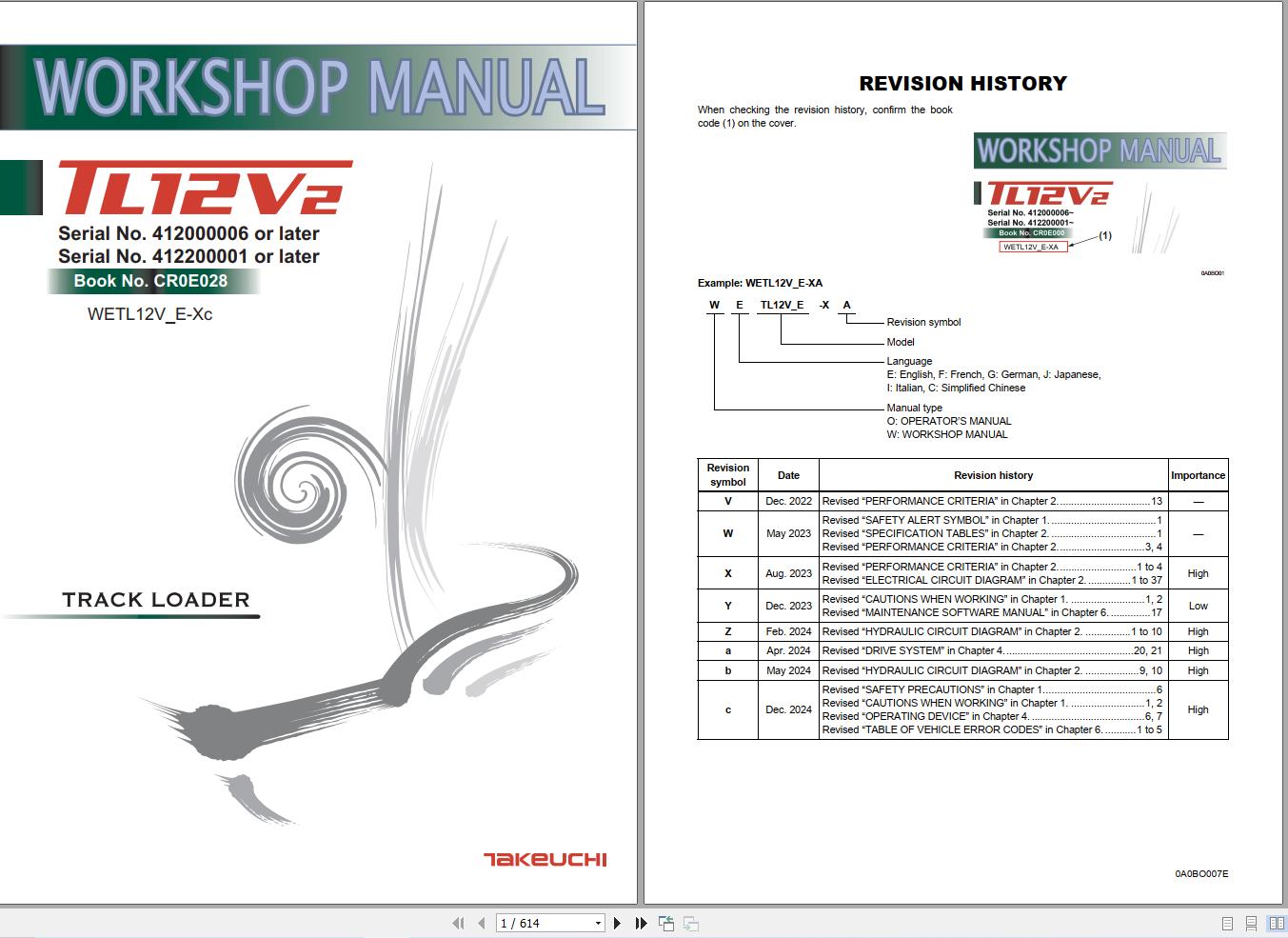
Takeuchi Track Loader TL12R2 Workshop Manual WETL12V_E-Xc
Size: 124.52 MB
Format: PDF
Language: English
Brand: Takeuchi
Type of Machine: Track Loader
Type of Manual: Workshop Manual, Electric and Hydraulic Diagrams
Model: Takeuchi TL12R2 Track Loader
Part Number: WETL12V_E-Xc
Number of Pages: 614 Pages
30 USD
- Description
Description
Contents:
1. SAFETY
SAFETY ALERT SYMBOL
SAFETY PRECAUTIONS
Observe all safety rules
Wear safe clothing and protective gear
Install an extinguisher and a first aid kit
Lockout/Tagout (LOTO)
Use the correct tools
Regularly replace the safety-critical parts
Explosionproof lighting
Prohibit access by unauthorized persons
Prepare the work area
When the canopy is tilted up
Keep the machine clean
Stop the engine before performing maintenance
Keep clear of the moving fan and belt
When working under the machine
When working on the machine
Securing the working equipment
Secure the engine hood and guard when they are open
Place heavy components in a stable position
Caution when filling with fuel or oil
Handling of hoses
Be careful with hot and pressurized components
Handling of radiator
Be careful with oils under pressure
Release the residual pressure from the hydraulic system before performing maintenance
Be careful with grease under pressure
Handling of the accumulator
Disconnect the battery
Use caution when handling batteries
Have a service agent repair welding cracks or other damage
Checks after maintenance
Disposing of wastes
Cautions for handling DEF/AdBlue®
CAUTIONS WHEN WORKING
Before starting work
When disassembling or assembling
When removing/installing the hydraulic unit
When connecting/disconnecting the hoses or pipes
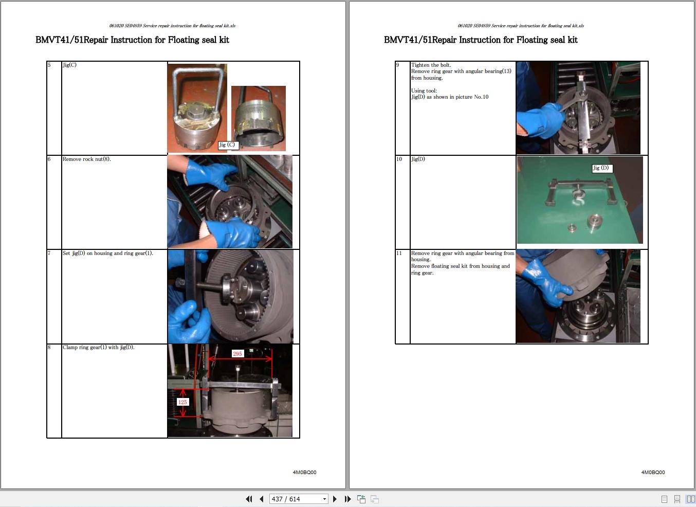
Handling of seals
Pressure adjustment for hydraulic devices2. SERVICE DATA
DIMENSIONAL DRAWING
Machine dimensions
Operating range
SPECIFICATION TABLES
Performance
Dimensions
Mass
Engine
Hydraulic system
Brake device
Undercarriage
Operating device
Working equipment
Hydraulic system
TABLE OF MASSES
Upper structure
Lower structure
Attachments
LUBRICANT AND FUEL CHART
Diesel fuel standards
Handling DEF/AdBlue®
PERFORMANCE CRITERIA
Standard values table
Hydraulic pump assignment table
Methods for inspecting performance
TIGHTENING TORQUE
Hydraulic hose
Bite-type pipe fitting for steel pipe
Joint for piping
Joint for piping (O-ring seal type)
Bolts and nuts (JIS strength category 10.9)
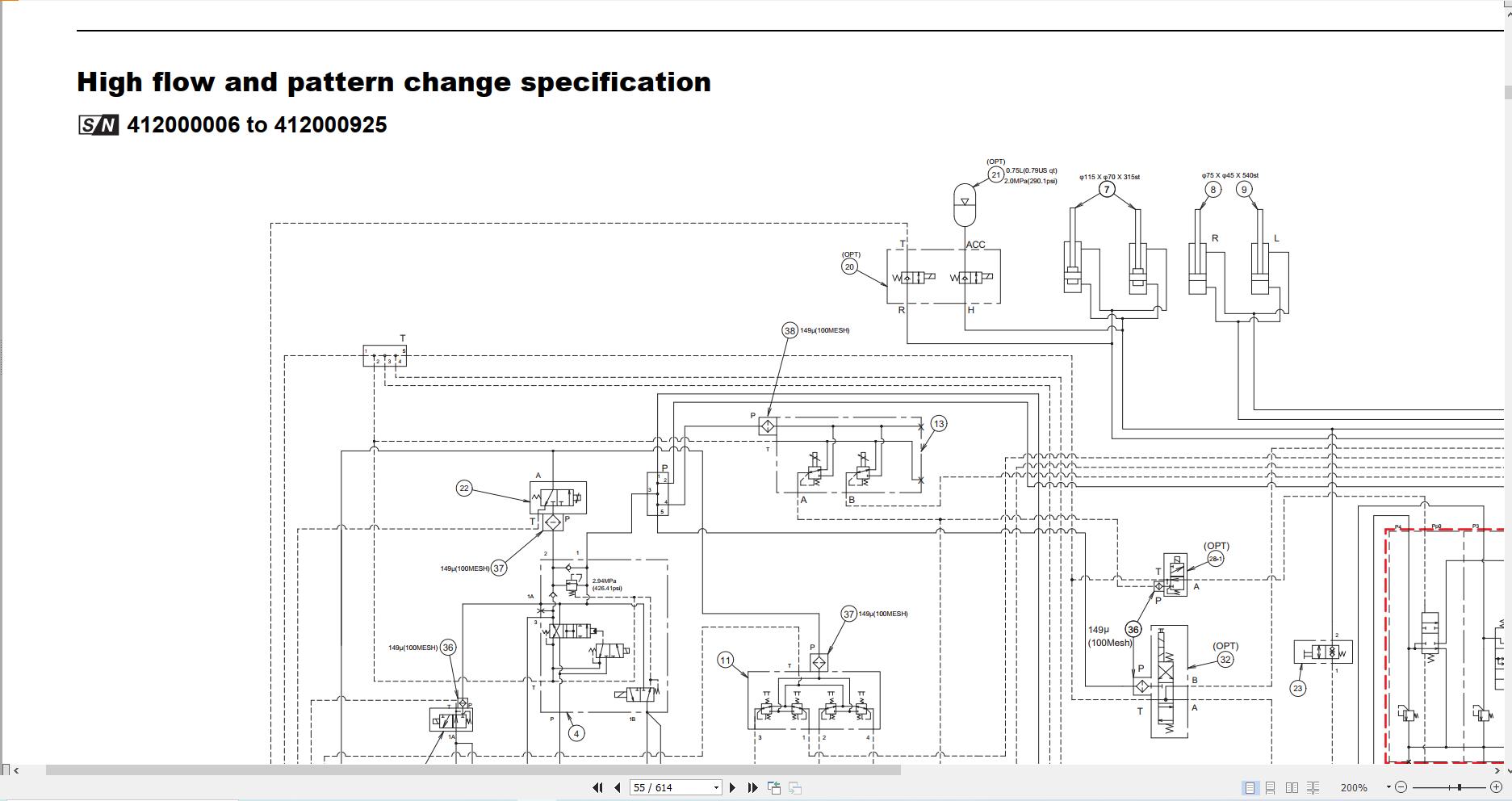
HYDRAULIC CIRCUIT DIAGRAM
Standard flow specification
High flow and pattern change specification
High flow specification
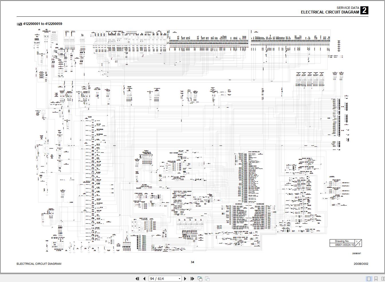
ELECTRICAL CIRCUIT DIAGRAM
Symbols in electrical circuit diagram
Schematic diagram
WIRE HARNESS
Wiring diagrams
HYDRAULIC DEVICE LAYOUT DIAGRAM3. FUNCTION
HST PUMP
Hydraulic pump
Control section
Charge check/high-pressure relief valve assembly
Charge relief valve
GEAR PUMP
CONTROL VALVE
At the neutral position
AUX1 operation
Arm-raising operation
Arm-lowering operation
Bucket roll-back operation
Bucket dump operation
Flow rate adjustment valve
When arm float is turned off
Arm float operation
Main relief valve
Overload relief valve
SUB VALVE
When the solenoid valve A is not energized:
When the solenoid valve A is energized:
When the solenoid valve B is not energized:
When the solenoid valve B is energized:
PILOT VALVE
When the lever (1) is in the neutral position:
When the lever (1) is tilted:
When the lever (1) is kept at a certain position:
PROPORTIONAL CONTROL SOLENOID VALVE (ACTIVE POWER CONTROL)
PROPORTIONAL SOLENOID VALVE (1ST SERVICE)
SOLENOID VALVE (PARKING BRAKE)
Solenoid valve
CYLINDER
Function
Operation
TRAVEL MOTOR4. DISASSEMBLY AND ASSEMBLY
SERVICE STANDARDS
Track roller A
Track roller B
Sprocket
Idler
Clearance for pin and bushing
Replacing the pin and bushing
DRIVE SYSTEM
Engine
Radiator
Hydraulic pump (without high-flow equipment)
Hydraulic pump (with high-flow equipment)
Fuel tank
TRAVEL SYSTEM
Track roller (Serial No.: 412000006 to 412000788)
Track roller (Serial No.: 412000789 to 412000918)
Track roller (Serial No.: From 412000919)
Front idler (Serial No.: 412000006 to 412000871)
Front idler (Serial No.: From 412000872)
Grease cylinder
Travel motor
FRAME
Tilting up the canopy and cab
Lift arm stopper
Floor frame
Cover
Canopy/cab
OPERATING DEVICE
Hydraulic pilot unit
Disassembly and assembly
ATTACHMENTS
Mechanical quick-hitch
Hydraulic quick-hitch
Lift arm
Hydraulic piping (machine without high-flow)
Hydraulic piping (machine with high-flow, machine with 2nd auxiliary line piping)
Hydraulic piping (machine with high-flow, machine with 2nd auxiliary line piping, machine with ride control)
Block coupler (machine without high-flow)
Block coupler (machine with high-flow, machine with 2nd auxiliary line piping)
HYDRAULIC TANK
Construction
Removing the hydraulic tank
Installing the hydraulic tank
Filling with hydraulic oil
Bleeding the air
HST PUMP
GEAR PUMP
Construction
Disassembly and assembly
GEAR PUMP (HIGH FLOW)
Construction
Disassembly and assembly
CONTROL VALVE
Construction
Disassembly
Assembly
Adjustment
SUB VALVE
Construction
Disassembly and assembly
Inspection and adjustment
PILOT VALVE
Construction
Special tools
Disassembly and assembly
Inspection and adjustment
SOLENOID VALVE (PARKING BRAKE)
Construction
Disassembly and Assembly
Inspection and adjustment
PROPORTIONAL CONTROL SOLENOID VALVE
Construction
Disassembly and Assembly
Inspection and adjustment
PROPORTIONAL CONTROL SOLENOID VALVE (1ST AUXILIARY LINE PIPING)
Construction
Disassembly and assembly
Service standards
CYLINDER
Construction diagram
Disassembly and assembly
Tools required
TRAVEL MOTOR5. TROUBLESHOOTING
ABOUT THE TROUBLESHOOTING SECTION
Notes on troubleshooting and servicing
OVERALL MACHINE
No operation is possible.
All systems working, but insufficient power.
Lift arm and bucket fail to move or are too slow.
TRAVELING
Traveling fails.
Right or left travel speed decelerates and the machine veers to one side.
Operating temperature of the travel system is too high.
2nd-speed travel is not possible.
LIFT ARM
Arm cylinder does not move
Arm cylinder moves too slowly or lacks force
When the control lever is pulled slowly, the lift arm drops once.
Spontaneous drop of the lift arm is too large.
BUCKET
Bucket cylinder does not move.
Bucket cylinder is slow or lacks force.
Spontaneous drop of the bucket is too large
SERVICE
The prescribed pressure is not supplied to the 1st service
HST PUMP
HST system
HST pump
GEAR PUMP
CONTROL VALVE
SUB VALVE
PILOT VALVE
PROPORTIONAL SOLENOID VALVE (ACTIVE POWER CONTROL, 1ST AUXILIARY LINE PIPING)
SOLENOID VALVE (PARKING BRAKE)
CYLINDER6. OTHER
MAINTENANCE SOFTWARE MANUAL
CONTENTS
1. OUTLINE
2. CONNECTION METHODS
3. DESCRIPTION OF FUNCTIONS
AIR CONDITIONER
Compressor assembly
Condenser assembly
Air conditioner unit
AC component
AIR CONDITIONER SYSTEM
Overview of System Operation
Inspection and Maintenance without gauges
Troubleshooting & Service Procedures
TABLE OF VEHICLE ERROR CODES
ENGINE ERROR CODES
Related Products
-
Takeuchi Track Loader TL220 Tl230 TL240 TL250 Operators Manual AU1E003
10 USDSize: 3.78 MBFormat: PDFLanguage: EnglishBrand: TakeuchiType of Machine: Track LoaderType of Manual: Operators ManualModel: Takeuchi TL220 Tl230 TL240 TL250 Track LoaderSerial Number:TL220 : 222000062-Tl230 : 223000123-TL240 : 224000081-TL250 : 225000075-Book Number: AU1E003Number of Pages: 200 Pages
REALEASE :
REALEASE :
-
Takeuchi Full Service Training, Operator – Part Manual 2019_EN DVD 15,5Gb
Original price was: 300.250Current price is: 250. USDTakeuchi Full Service Operator, Part Manual Manual 2019_EN DVD 15,5GbHigh speed link downloadInstruction: Present COMBO INCLUDING: 1/ Takeuchi Service Manual New Model 2019_EN DVDSize: 7.24 GbLanguage: EnglishBand: TakeuchFormat: pdfUpdated new 2019Type: Takeuchi Workshop Manual, Part Manual, Operator Manual1 DVD: PresentHigh Speed link download DETAIL CONTENTS: ” CLICK HERE “ 2/ Takeuchi Full Set Service Training, Service Manual, Operator, Part ManualSize: 8,26GbLanguage: EnglishType: Service Training, Service Manual, OperatoR, Part ManualFormat: pdf, pptContents:1/ Moteur2/ Operator manuals3/ Parts4/ Presentation5/ Service manuals6/ Service tool TNV7/ TKB BREAKER8/ Training Manual 2009 DETAIL CONTENTS: ” CLICK HERE “Hot-17%
REALEASE :
22.11.2019
REALEASE :
22.11.2019
-
Takeuchi Track Loader TL250 Parts Manual BU3Z007-1-0
15 USDSize: 40.29 MBFormat: PDFLanguage: EnglishBrand: TakeuchiType of Machine: Track LoaderType of Manual: Parts ManualModel: Takeuchi TL250 Track LoaderSerial Number: 225000001-UPPart Number: BU3Z007-1-0Number of Pages: 581 Pages
REALEASE :
REALEASE :
-
Takeuchi Track Loader TL230 Parts Manual P-TL230BBG
15 USDSize: 48.55 MBFormat: PDFLanguage: EnglishBrand: TakeuchiType of Machine: Track LoaderType of Manual: Parts ManualModel: Takeuchi TL230 Track LoaderSerial Number: 223100001-Part Number: P-TL230BBGPublication Date: BU5Z005-1-0Number of Pages: 415 Pages
REALEASE :
REALEASE :
-
Takeuchi Service Manual New Model 2019_EN DVD
Original price was: 200.150Current price is: 150. USDTakeuchi Service Manual New Model 2019_EN DVDSize: 7.24 GbLanguage: EnglishBand: TakeuchFormat: pdfUpdated new 2019Type: Takeuchi Workshop Manual, Part Manual, Operator Manual1 DVD: PresentHigh Speed link downloadHot-25%
REALEASE :
13.09.2019
REALEASE :
13.09.2019
-
Takeuchi Track Loader TL240 Parts Manual BU2Z006-1-0
15 USDSize: 58.61 MBFormat: PDFLanguage: EnglishBrand: TakeuchiType of Machine: Track LoaderType of Manual: Parts ManualModel: Takeuchi TL240 Track LoaderSerial Number: 224000001-UPPart Number: BU2Z006-1-0Number of Pages: 490 Pages
REALEASE :
REALEASE :
-
Takeuchi Track Loader TL230 Parts Manual BU1Z007-2-0
15 USDSize: 57.90 MBFormat: PDFLanguage: EnglishBrand: TakeuchiType of Machine: Track LoaderType of Manual: Parts ManualModel: Takeuchi TL230 Track LoaderSerial Number: 223000001-Part Number: BU1Z007-2-0Number of Pages: 442 Pages
REALEASE :
REALEASE :
-
Takeuchi Track Loader TL230A Series 2 Parts Manual BU5Z005
15 USDSize: 50.91 MBFormat: PDFLanguage: EnglishBrand: TakeuchiType of Machine: Track LoaderType of Manual: Parts ManualModel: Takeuchi TL230A Series 2 Track LoaderSerial Number 223100001-Part Number: BU5Z005Number of Pages: 463 Pages
REALEASE :
REALEASE :