
4 ITEMSVIEW CART


Total: 100.00
Expert Support
Full Speed
100% Working
30 USD
Contents:
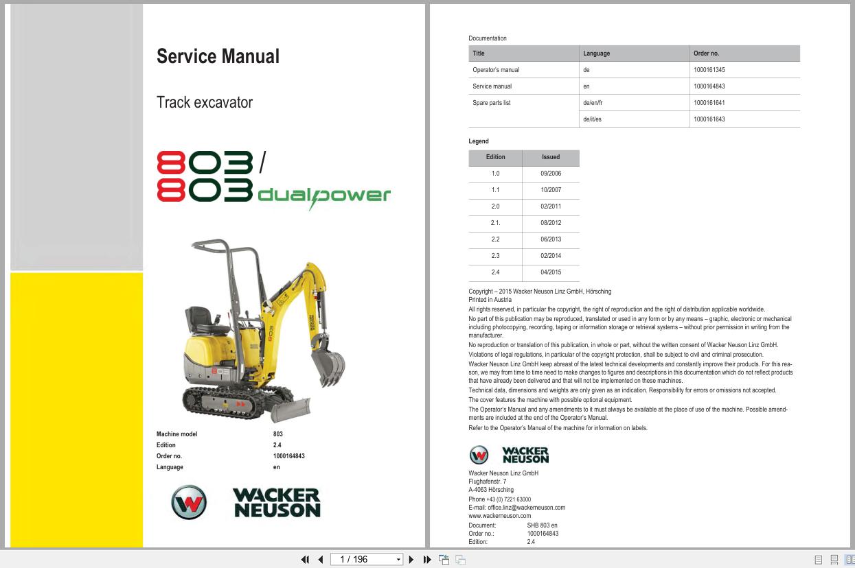
1 Operation
1.1 Important information on this service manual
1.2 Identification of warnings and dangers
1.3 Designated use and exemption from liability
1.4 Type labels and component numbers
1.5 Machine: overview
1.6 Operating equipment: overview
1.7 Operating equipment: legend
1.8 Maintenance prop
1.9 Centre pivot prop
2 Specifications
2.1 Chassis
2.2 Engine
2.3 Travelling drive
2.4 Brakes
2.5 Steering system
2.6 Work hydraulics
2.7 Loader unit
2.8 Drive specifications
2.9 Vibration
2.10 Electric system (up to BB001360)
2.11 Electric system (from AB100001H)
2.12 Tyres
2.13 Noise levels
2.14 Coolant compound table
2.15 General tightening torques
2.16 Dimensions model 1001
3 Maintenance
3.1 Fluids and lubricants
3.2 Maintenance plan (overview)
3.3 Service package
3.4 Introduction
3.5 Fuel system
3.6 Engine lubrication system
3.7 Cooling system
3.8 Air filter
3.9 V-belt
3.10 Hydraulic system
3.11 Lubrication points
3.12 Tyre maintenance
3.13 Changing wheels
3.14 Electric system
3.15 Battery master switch
3.16 General maintenance work
4 Engine
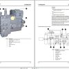
4.1 Engine overview 3TNE74 (up to BB001360)
4.2 Fuel system (up to BB001360)
4.3 Engine overview 3TNV76-XNSV (from AB100001H)
4.4 Fuel system (from AB100001H)
4.5 Checking and adjusting valve tip clearance
4.6 Tightening order for cylinder head bolts
4.7 Checking the injection nozzles
4.8 Checking the nozzle jet
4.9 Fuel injection time (up to BB001360)
4.10 Fuel injection time (from AB100001H)
4.11 Adjusting engine revs
4.12 Compression
4.13 Checking the coolant thermostat
4.14 Checking the thermal switch
4.15 Oil pressure switch
4.16 Checking the coolant circuit
4.17 Engine trouble
5 Travelling drive
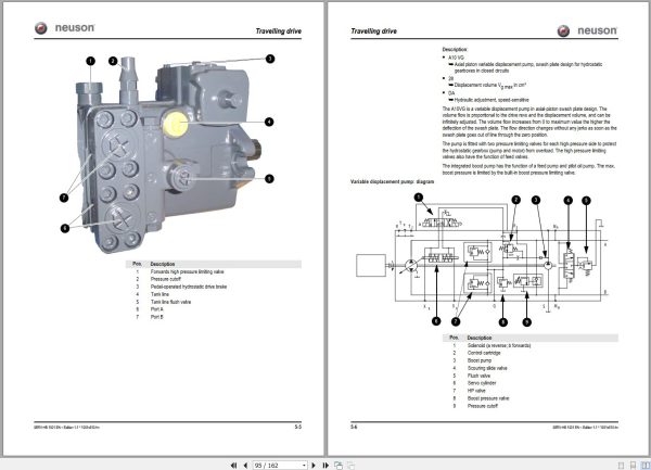
5.1 Variable displacement pump A10VG45DA (up to BB001360)
5.2 Variable displacement pump A10VG28DA (from AB100001H)
5.3 Rear hydraulic motor
5.4 Front hydraulic motor
5.5 Travelling drive: overview
5.6 Towing and transporting the machine
5.7 Test instruction
6 Brakes
6.1 Brake circuit up to serial no. BB001360
6.2 Brake circuit from serial no. BB001361
7 Steering system
7.1 Steering circuit
7.2 Steering unit: diagram
7.3 Steering unit connections
7.4 Steering unit: overview
8 Hydraulic system
8.1 Control valve connections: overview
8.2 Test instructions
8.3 Diagram up to serial no. BB001360
8.4 Diagram up to serial no. BB001360: legend
8.5 Diagram from serial no. AB100001H
8.6 Diagram from serial no. AB100001H: legend
8.7 Hydraulics diagram A3 up to serial no. BB001360
8.8 Hydraulics diagram A3 from serial no. AB10001H
9 Electric system
9.1 Ohm’s Law (current, voltage, resistance); power
9.2 Measuring equipment, measuring methods
9.3 Relays
9.4 Electric components
9.5 Fuse box in instrument panel (up to BB001360)
9.6 Instrument panel up to BB001360: overview
9.7 Fuse box in instrument panel (from AB100001H)
9.8 Instrument panel (from AB100001H): overview
9.9 Wiring diagram up to serial no. BB001360: legend
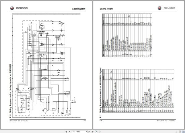
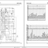
9.10 Wiring diagram version 1 A4 up to serial no. BB001360
9.11 Wiring diagram from serial no. AB100001H: legend
9.12 Wiring diagram version 1 A4 from serial no. AB100001H
9.13 Main wiring harness from AB100001H: legend
9.14 Main wiring harness from AB100001H
9.15 Engine wiring harness from AB100001H: legend
9.16 Engine wiring harness from AB100001H
9.17 Wiring diagram A3 up to serial no. BB001360: legend
9.18 Wiring diagram A3 up to serial no. BB001360
9.19 Wiring diagram A3 from serial no. AB100001H: legend
9.20 Wiring diagram A3 from serial no. AB100001H
9.21 Main wiring harness from AB100001H: legend
9.22 Main wiring harness from AB100001H
9.23 Engine wiring harness from AB100001H: legend
9.24 Engine wiring harness from AB100001H

REALEASE :
12.18.2021
REALEASE :
12.18.2021

REALEASE :
REALEASE :

REALEASE :
14.07.2020
REALEASE :
14.07.2020

REALEASE :
REALEASE :

REALEASE :
01.11.2022
REALEASE :
01.11.2022
REALEASE :
REALEASE :
REALEASE :
REALEASE :

REALEASE :
REALEASE :
 Automotive - Heavy Equipment - Truck & Bus - Forklift - Crane