
0 ITEMSVIEW CART

✓
Expert Support
✓
Full Speed
✓
100% Working
Wacker Neuson Dumper 5001 Service Manual and Diagram 1000159455
Size: 25.79 MB
Format: PDF
Language: English
Brand: Wacker Neuson
Type of Machine: Dumper
Type of Manual: Service Manual, Electrical and Hydraulic Diagram
Model: Wacker Neuson 5001 Dumper
Part Number: 1000159455
Publication Date: 2009
Number of Pages: 275 Pages
30 USD
- Description
Description
Contents:
1 Operation
1.1 Important information on this service manual
1.2 Identification of warnings and dangers
1.3 Designated use and exemption from liability
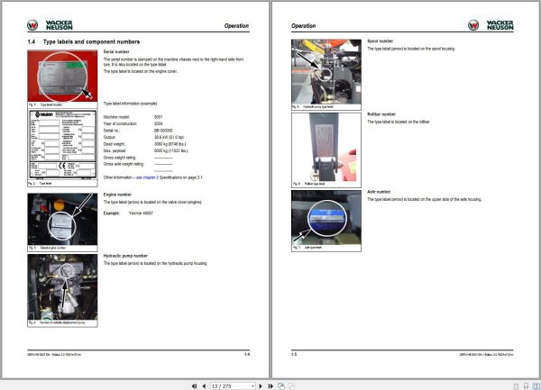
1.4 Type labels and component numbers
1.5 Machine overview
1.6 Control elements from AB45091D to AC45157D (overview)
1.7 Control elements from AD51001D (overview)
1.8 Maintenance strut
2 Specifications
2.1 Chassis
2.2 Engine
2.3 Travelling drive
2.4 Brakes
2.5 Steering system
2.6 Work hydraulics
2.7 Loader unit
2.8 Drive specifications
2.9 Vibration
2.10 Electrical system
2.11 Tyres
2.12 Axle mounting
2.13 Noise levels
2.14 Coolant compound table
2.15 General tightening torques
2.16 Dimensions model 5001 AB45091D to AC45157D
2.17 Dimensions model 5001 from AD51001D
3 Maintenance
3.1 Fluids and lubricants
3.2 Maintenance plan (overview)
3.2 Fuel system
3.3 Engine lubrication system
3.4 Cooling system
3.5 Air filter
3.6 V-belts
3.7 Hydraulic system
3.8 Lubrication points
3.9 Tyre maintenance
3.10 Changing wheels
3.11 Electrical system
3.12 Battery master switch
3.13 General maintenance work
3.14 Test report from AD51001D
4 Engine
4.1 Engine overview 4TNV84T-KNSV (up to AB45291D)
4.2 Fuel system
4.3 Checking the injection nozzles
4.4 Adjusting engine speed
4.5 Compression
4.6 Checking the coolant thermostat
4.7 Oil pressure switch
4.8 Checking the coolant circuit
4.9 Clutch
4.10 Engine trouble
4.11 Engine overview DEUTZ F4M 2011 (from AC45039D to AC45157D)
4.12 Fuel system
4.13 Checking and adjusting valve lash
4.14 Checking and adjusting the fuel injectors
4.15 Adjusting engine speed
4.16 Compression pressure
4.17 Removing/mounting the cylinder head
4.18 Replacing the injection pump/setting fuel injection time
4.19 Oil pressure switch
4.20 Engine trouble
4.21 Engine overview DEUTZ D2011 L04w (from AD51001D)
4.22 Fuel system
4.23 Checking and adjusting valve lash
4.24 Checking and adjusting the fuel injectors
4.25 Adjusting engine speed
4.26 Water pump and thermostat
4.27 Exhaust gas recirculation (external)
4.28 Compression pressure
4.29 Removing/mounting the cylinder head
4.30 Replacing the injection pump/setting fuel injection time
4.31 Oil pressure switch
4.32 Engine trouble
5 Travelling drive
5.1 Travelling drive overview
5.2 Variable displacement pump A4VG56DA
5.3 Replacing components
5.4 Variable displacement motor
5.5 Replacing components
5.6 Towing and transporting the machine
5.7 Test instructions for variable displacement pump
5.8 Test instructions for variable displacement motor
6 Axles
6.1 Axle type label
6.2 Drain, fill and check plug
6.3 Tightening torque
6.4 Transfer gearbox
6.5 Semiaxles
6.6 Wheel hub
6.7 Front axle brake
6.8 Cardan shaft
6.9 Dismantling and assembling the axle
7 Brakes
7.1 Brake circuit
7.2 Parking brake
7.3 Dismantling and assembling the brakes and the parking brake
8 Steering system
8.1 Steering circuit up to AC45157D
8.2 Steering unit: diagram
8.3 Steering unit connections
8.4 Steering unit overview
9 Hydraulic system
9.1 Manual spool overview and connections (Yanmar engine up to AB45291D)
9.2 Manual spool overview and connections (Deutz engine up to AC45157D)
9.3 Manual spool overview and connections (from AD51001D)
9.4 Valves
9.5 Dumping the skip: hydraulics diagram (up to AC45157D)
9.6 Swivelling the skip: hydraulics diagram (up to AC45157D)
9.7 Dumping and swivelling the skip: hydraulics diagram (from AD51001D)
9.8 Test instructions
9.9 Diagram A4 (up to AC45157D)
9.10 Diagram (legend)
9.11 Diagram A4 (from AD51001D)
9.12 Diagram (legend)
9.13 Hydraulics diagram A3 (up to AC45157D)
9.14 Hydraulics diagram A3 (starting AD51001D)
10 Electrical system
10.1 Ohm’s Law (current, voltage, resistance); power
10.2 Measuring equipment, measuring methods
10.3 Relays
10.4 Electric units
10.5 Fuse box
10.6 Control elements from AB45091D to AC45157D (overview)
10.7 Control elements from AD51001D (overview)
10.8
10.9 Wiring diagram legend (up to AB45291D)
10.10 Wiring diagram version 1 A4 (up to AB45291D)
10.11 Wiring diagram version 2 A4 (from AC45039D to AC45157D)
10.12 Wiring diagram version 3 A4 (from AD51001D)
10.13 Wiring harness legend 1000115009 main wiring harness (up to AB45291D)
10.14 Wiring harness 1000115009: main wiring harness (up to AB45291D)
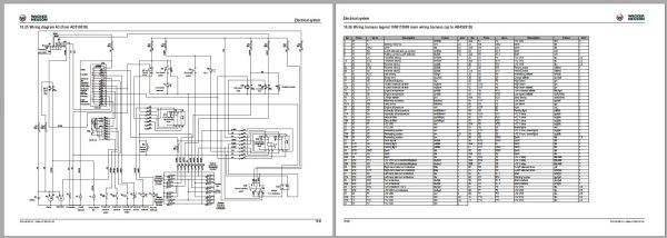
10.15 Main wiring harness legend (from AC45039D to AC45157D)
10.16 Main wiring harness (from AC45039D to AC45157D)
10.17 Main wiring harness (from AD51001D)
10.18 Engine wiring harness legend (from AC45039D to AC45157D)
10.19 Engine wiring harness (from AC45039D to AC45157D)
10.20 STVO (Austrian road traffic regulations) wiring harness and rotating beacon (from AD51001D)
10.21 Connector assignment for light switch and forwards-reverse control
10.22 Wiring diagram legend A3 up to serial no. AB45291D
10.23 Wiring diagram A3 up to AB45291D
10.24 Wiring diagram A3 (from AC45039D to AC45157D)
10.25 Wiring diagram A3 (from AD51001D)
10.26 Wiring harness legend 1000115009 main wiring harness (up to AB45291D)
10.27 Wiring harness 1000115009: main wiring harness (up to AB45291D)
10.28 Wiring harness 1000181595 main wiring harness (from AD51001D)
10.29 Main wiring harness legend 1000181595A (from AD51001D)
10.30 Wiring harness 1000181595A main wiring harness (from AD51001D)
10.31 Wiring harness legend 1000115414 engine wiring harness (up to AB45291D)
10.32 Wiring harness 1000115414 engine wiring harness (up to AB45291D)
10.33 Wiring harness legend: telltale/indicator base – ignition lock base (up to AB45291D)
10.34 Wiring harness 1000075039 telltale/indicator base (up to AB45291D)
10.35 Connector assignment for light switch and forwards-reverse control
10.36 Main wiring harness legend (from AC45039D to AC45157D)
10.37 Main wiring harness (from AC45039D to AC45157D)
Related Products
-
Wacker Neuson Track Excavator EZ17 Parts and Operation Service Manual
80 USDSize: 134.58 MBFormat: PDFLanguage: EnglishBrand: Wacker NeusonType of Machine: Track ExcavatorType of Manual: Service Manual, Operation Manual, Parts Manual, Electric and Hydraulic DiagramsModel: Wacker Neuson EZ17 Track Excavator
REALEASE :
REALEASE :
-
Wacker Neuson Excavator Deere 26P Parts and Repair Service Manual
80 USDSize: 216.88 MBFormat: PDFLanguage: EnglishBrand: Wacker NeusonType of Machine: ExcavatorType of Manual: Repair Service Manual, Parts Manual, Electric and Hydraulic DiagramsModel: Wacker Neuson Deere 26P Excavator
REALEASE :
REALEASE :
-
Wacker Neuson PDF DVD Collection Service Part & Operator Manual_EN
Original price was: 150.90Current price is: 90. USDWacker Neuson PDF DVD Collection Service Part & Operator Manual_ENSize: 731 MBFormat : PDFLanguage : EnglishBrand: Wacker NeusonNumber of page: 61 FolderAmount of DVD: 1 DVDWindow: All Window 32 an d 64 bitType of machine: Wacker Neuson Heavy EquipmentType of document: Service Part & Operator ManualHot-40%
REALEASE :
14.07.2020
REALEASE :
14.07.2020
-
Wacker Neuson Track Excavator EZ26 Operation Service Manual
60 USDSize: 172.34 MBFormat: PDFLanguage: EnglishBrand: Wacker NeusonType of Machine: Track ExcavatorType of Manual: Service Manual, Operation Manual, Electric and Hydraulic DiagramsModel: Wacker Neuson EZ26 Track Excavator
REALEASE :
REALEASE :
-
Wacker Neuson 23.1GB PDF Part Manual, Operator Manual, Repair Manual & Wiring Diagram DVD
Original price was: 400.240Current price is: 240. USDWacker Neuson 23.1GB PDF Part Manual, Operator Manual, Repair Manual & Wiring Diagram DVDSize: 23.1 Gb (PDF Files)Language: EnglishFormat: PDFBrand: Wacker NeusonOS: All WindowsQuantity of CD: 1 DVDHigh-Speed link DownloadType of document: Part Manual, Operator Manual, Repair Manual, Electric Diagram, Hydraulic DiagramHot-40%
REALEASE :
01.11.2022
REALEASE :
01.11.2022
-
Wacker Neuson Dumper 1501 D01-05 Spare Parts Catalog 1000165936
Original price was: 20.10Current price is: 10. USDSize: 12.09 MBFormat: PDFLanguage: English, German, FrenchBrand: Wacker NeusonType of Machine: DumperType of Manual: Parts ManualModel: Wacker Neuson 1501 D01-05 DumperPart Number: 1000165936Publication Date: 2016Number of Pages: 255 Pages-50%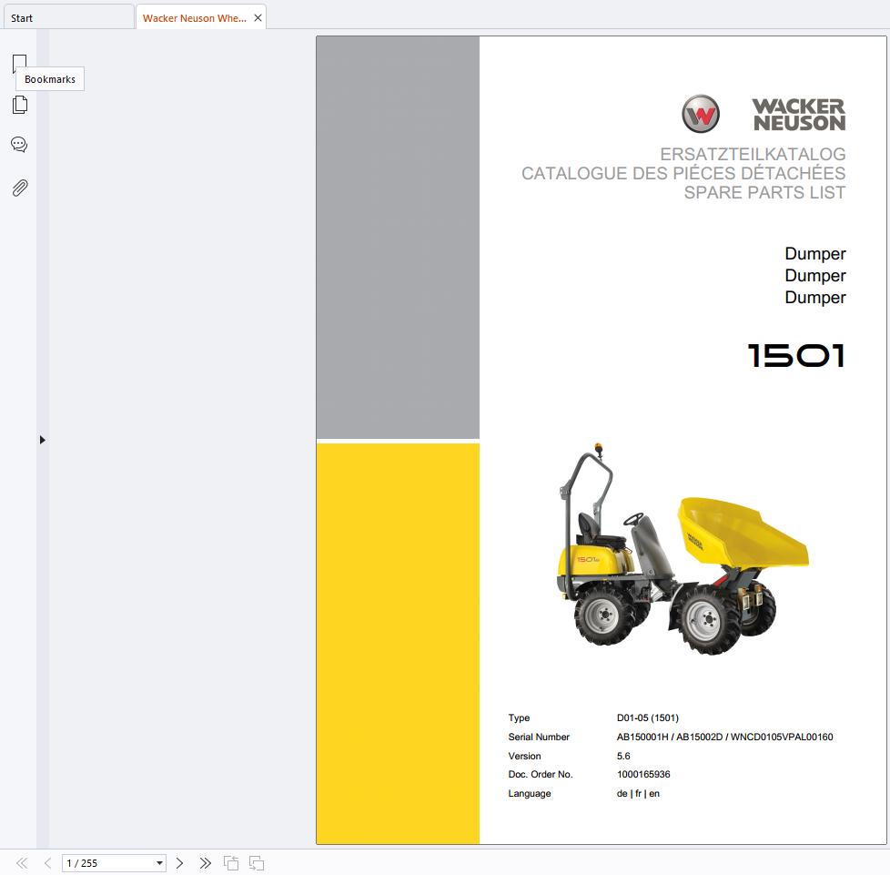
REALEASE :
REALEASE :
-
Wacker Neuson 4.91GB PDF DVD Collection Service Part Diagrams Assembly & Operator Manual
Original price was: 200.140Current price is: 140. USDWacker Neuson 4.91GB PDF DVD Collection Service Part Diagrams Assembly & Operator ManualSize: 4.91 GB (Unpack)Format : PDFLanguage : English, German, FranceBrand: Wacker NeusonNumber of Folder: 1,293 Files, 188 FoldersAmount of DVD: 1 DVDWindow: All Window 32 and 64 bitType of machine: Wacker Neuson Heavy Equipment– Wacker Neuson Dumper– Wacker Neuson Excavator– Wacker Neuson Skid Steer Loader– Wacker Neuson Roller– Wacker Neuson Telehandler…Type of document:– Service Manual– Operating Manual– Spare Part List (English, German, France Langues)– Diagrams– Service News– Assembly InstructionsHigh-Speed link downloadHot-30%
REALEASE :
12.18.2021
REALEASE :
12.18.2021
-
Wacker Neuson Track Excavator 803 803 Dualpower Service Manual 1000164843
20 USDSize: 9.90 MBFormat: PDFLanguage: EnglishBrand: Wacker NeusonType of Machine: Track ExcavatorType of Manual: Service Manual, Hydraulic and Electric DiagramsModel: Wacker Neuson 803, 803 Dualpower Track ExcavatorOrder Number: 1000164843Number of Pages: 196 Pages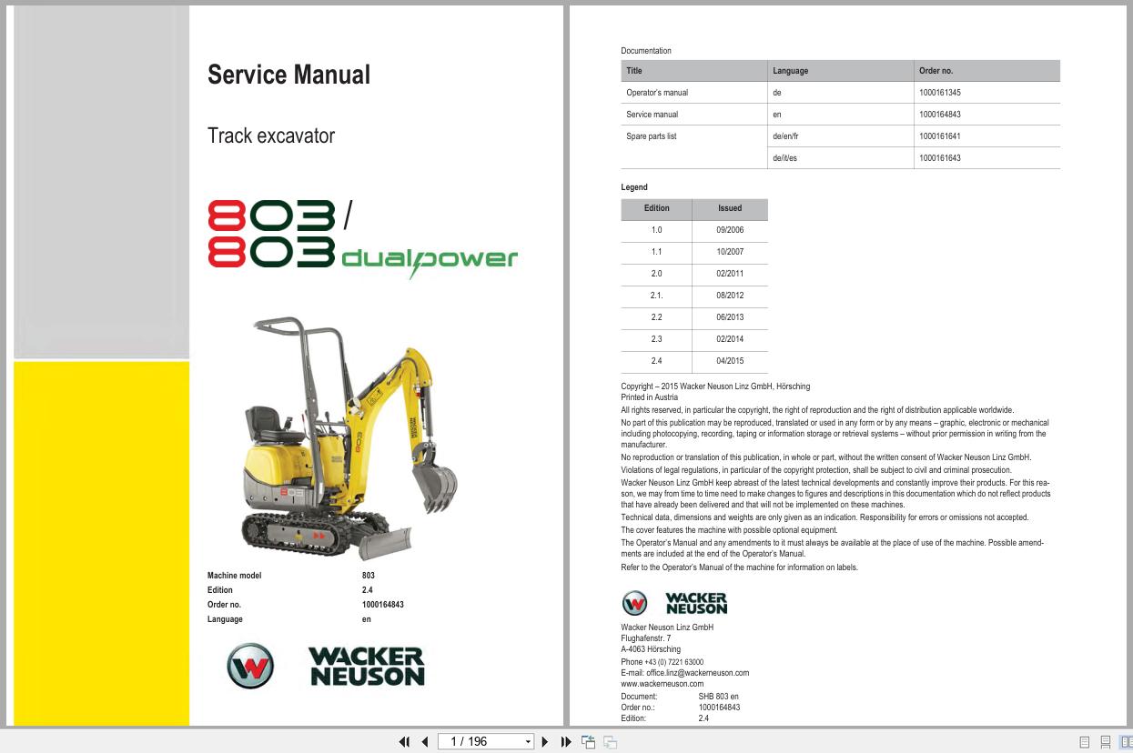
REALEASE :
REALEASE :