
0 ITEMSVIEW CART

✓
Expert Support
✓
Full Speed
✓
100% Working
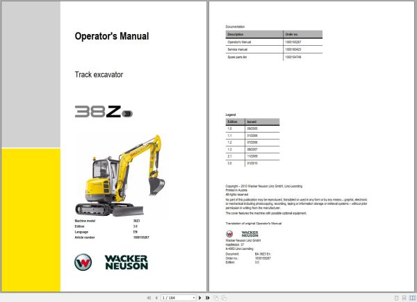
Wacker Neuson Excavator 38Z3 Operating Manual 1000155267
Size: 43.58 MB
Format: PDF
Language: English
Brand: Wacker Neuson
Type of Machine: Excavator
Type of Manual: Operating Manual
Model: Wacker Neuson 38Z3 Excavator
Part Number: 1000155267
Publication Date: 2010
Number of Pages: 164 Pages
10 USD
- Description
Description
Contents:
Important information on this Operator’s Manual
Machine overview
Brief description
Fields of application, attachments
Regulations
EC declaration of conformity version 38Z³ up to serial number AG00572
EC declaration of conformity version 38Z³ from serial number AG00573
Type labels and component numbers
Other signs and symbols
Fire extinguisher
Identification of warnings and dangers
Warranty
Designated use and exemption from liability
General conduct and safety instructions
Safety instructions regarding operation
Safety instructions for maintenance
Warning of special hazards
Cab overview
Instrument panel overview
Putting into operation
Driving the excavator
Driving on slopes
Tilting the cab
Working with the machine
Control levers/ISO controls: overview
Changeover valve for SAE/ISO controls (option)
Control lever with proportional controls (option): overview
Control lever if equipped with 3rd control circuit (option): overview
Releasing the pressure on the work hydraulics
Re-equipping attachments
Hydraulic quickhitch (option)
Powertilt (option)
Connections for auxiliary hydraulics
Grading
Safe load indicator (option)
Engine trouble
Malfunctions of the Powertilt unit
Introduction
Fuel system
Engine lubrication system
Engine and hydraulics cooling system
Air filter
V-belt
Hydraulic system
Pilot valve
Tracks
Travelling drive
Electrical system
General maintenance work
Maintenance if the machine is out of service for a longer period of time
Fluids and lubricants
Maintenance plan (overview)
Maintenance label
Chassis
Engine
Undercarriage and swivel unit
Stabiliser blade
Work hydraulics
Noise levels
Vibration
Coolant compound table
Powertilt
Dimensions model 38Z³
Lift capacity table 38Z³
Lift capacity table 38Z³ counterweight (option)
Lift capacity table 38Z³ long stick (option)
Lift capacity table 38Z³ long stick, counterweight (option)
Symbole
A
B
C
D
F
H
I
L
M
N
O
P
R
S
T
V
W
1 Introduction
1.1 Important information on this Operator’s Manual
1.2 Machine overview
1.3 Brief description
Travelling drive
Work hydraulics
Cooling system
Cab (ROPS, TOPS and FOPS)
1.4 Fields of application, attachments
Use: attachment
1.5 Regulations
1.6 EC declaration of conformity version 38Z³ up to serial number AG
1.7 EC declaration of conformity version 38Z³ from serial number AG
1.8 Type labels and component numbers
1.9 Other signs and symbols
…on the outside of the machine
…inside the cab
1.10 Fire extinguisher
2 Safety instructions
2.1 Identification of warnings and dangers
2.2 Warranty
2.3 Designated use and exemption from liability
2.4 General conduct and safety instructions
Organisational measures
Selection and qualification of staff, basic responsibilities
2.5 Safety instructions regarding operation
Normal operation
Applications with lifting gear
Trailers and attachments
Transport
2.6 Safety instructions for maintenance
2.7 Warning of special hazards
Electrical energy
Gas, dust, steam, smoke
Hydraulics
Noise
Oil, grease and other chemical substances
Battery
Tracks
3 Operation
3.1 Cab overview
3.2 Instrument panel overview
3.3 Putting into operation
Safety instructions
Putting the machine into operation for the first time
Running-in period
Check lists
Start-up checklist
Operation checklist
Parking checklist
3.4 Driving the excavator
Preheating start switch
Throttle
Automatic revs setting (option)
Telltales and warning lights: overview
Before starting the engine
Starting the engine: general
Procedure
Starting with the drive interlock (option)
Starting at low temperatures
When the engine has started …
Engine warm-up
Jump-starting the engine (supply battery)
Special instructions for driving on public roads
Moving off
Drive levers
High speed
Hydraulic brake
Mechanical brake
3.5 Driving on slopes
Specific safety instructions
Driving on slopes
Stabiliser blade operation
Parking the machine
Parking the machine on slopes
Light system
Roof lights (option)
Interior light
Rotating beacon (option)
Cab heating and ventilation
Heating adjustment
Washer system
Tank for washer system
Air conditioning (option)
Recirculated air mode
Seat adjustment
Weight adjustment
Height adjustment
Horizontal adjustment
Backrest adjustment
Seat belt
Emergency exit
Front window
Door
Engine cover
Battery master switch (model 38Z3)
3.6 Tilting the cab
Exit through the door
Adjusting the left-hand side armrest
Towing the track excavator
Towing
Crane handling the machine
Loading and transporting the machine
Tying down the machine
3.7 Working with the machine
General safety instructions
3.8 Control levers/ISO controls: overview
Left-hand side control lever
Boom swivel controls
Lowering the boom with the engine stopped
Releasing pressure
Rotating the upper carriage
Swivel unit brake
3.9 Changeover valve for SAE/ISO controls (option)
Right-hand side control lever
Directional valve position
Directional valve
3.10 Control lever with proportional controls (option): overview
Function
Measures to be taken in case of malfunctions
Changeover between auxiliary hydraulics and boom swivel
Switching the status indicator on/off for auxiliary hydraulics/boom swivel
Operating the boom/auxiliary hydraulics
Hammer operation
Adjusting control response:
Characteristic curves – status indicator
3.11 Control lever if equipped with 3rd control circuit (option): overview
3.12 Releasing the pressure on the work hydraulics
Pressure release with proportional controls (option)
3.13 Re-equipping attachments
Removing a bucket
Mounting a bucket
Quickhitch (option)
3.14 Hydraulic quickhitch (option)
Maintenance
Operation
3.15 Powertilt (option)
Re-equipping
Mounting the Powertilt unit
Removing the Powertilt unit
Port
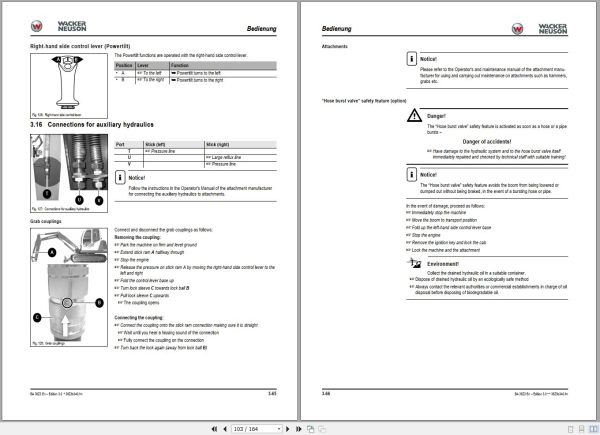
Right-hand side control lever (Powertilt)
3.16 Connections for auxiliary hydraulics
Grab couplings
Attachments
“Hose burst valve†safety feature (option)
Working with the standard bucket
Inadmissible work
Excavator work position
Bucket position when digging
Excavating trenches
Loading
Grading
Excavating trenches sideways
3.17 Grading
Working alongside trenches
Stabiliser blade at rear
3.18 Safe load indicator (option)
4 Troubleshooting
4.1 Engine trouble
4.2 Malfunctions of the Powertilt unit
5 Maintenance
5.1 Introduction
5.2 Fuel system
Refuelling
Stationary fuel pumps
Diesel fuel specification
Bleeding the fuel system
Fuel prefilter with water separator
5.3 Engine lubrication system
Checking the oil level
Filling up engine oil
5.4 Engine and hydraulics cooling system
Checking/filling up coolant
5.5 Air filter
Replacing the filter
5.6 V-belt
Checking V-belt tension
Retightening the V-belt
Checking the V-belt of the air conditioning system
Tightening the V-belt of the air conditioning system
5.7 Hydraulic system
Checking the hydraulic oil level
Filling up hydraulic oil
Important information for the use of biodegradable oil
5.8 Pilot valve
Checking hydraulic pressure lines
5.9 Tracks
Checking track tension
Setting the tracks
5.10 Travelling drive
Checking the oil level and filling up oil
Draining oil
Maintenance of attachments
5.11 Electrical system
Service and maintenance work at regular intervals
Instructions concerning specific components
Alternator
5.12 General maintenance work
Cleaning
General instructions for all areas of the machine
Inside the cab
Exterior of the machine
Engine compartment
Screw connections and attachments
Pivots and hinges
Powertilt (option)
5.13 Maintenance if the machine is out of service for a longer period of time
Preparatory work before taking the machine out of service
Putting the machine into operation again
5.14 Fluids and lubricants
Additional oil change and filter replacement (hydraulics)
5.15 Maintenance plan (overview)
5.16 Maintenance label
Explanation of symbols on the maintenance label
6 Specifications
6.1 Chassis
6.2 Engine
6.3 Hydraulic system
6.4 Undercarriage and swivel unit
6.5 Stabiliser blade
6.6 Work hydraulics
6.7 Electrical system
Fuse box under the seat on the left
Main fuse box with relays at the upper left in the engine compartment
Relays
6.8 Noise levels
6.9 Vibration
6.10 Coolant compound table
6.11 Powertilt
6.12 Dimensions model 38Z³
6.13 Lift capacity table 38Z³
6.14 Lift capacity table 38Z³ counterweight (option)
6.15 Lift capacity table 38Z³ long stick (option)
6.16 Lift capacity table 38Z³ long stick, counterweight (option)
Related Products
-
Wacker Neuson Track Excavator EZ26 Operation Service Manual
60 USDSize: 172.34 MBFormat: PDFLanguage: EnglishBrand: Wacker NeusonType of Machine: Track ExcavatorType of Manual: Service Manual, Operation Manual, Electric and Hydraulic DiagramsModel: Wacker Neuson EZ26 Track Excavator
REALEASE :
REALEASE :
-
Wacker Neuson 4.91GB PDF DVD Collection Service Part Diagrams Assembly & Operator Manual
Original price was: 200.140Current price is: 140. USDWacker Neuson 4.91GB PDF DVD Collection Service Part Diagrams Assembly & Operator ManualSize: 4.91 GB (Unpack)Format : PDFLanguage : English, German, FranceBrand: Wacker NeusonNumber of Folder: 1,293 Files, 188 FoldersAmount of DVD: 1 DVDWindow: All Window 32 and 64 bitType of machine: Wacker Neuson Heavy Equipment– Wacker Neuson Dumper– Wacker Neuson Excavator– Wacker Neuson Skid Steer Loader– Wacker Neuson Roller– Wacker Neuson Telehandler…Type of document:– Service Manual– Operating Manual– Spare Part List (English, German, France Langues)– Diagrams– Service News– Assembly InstructionsHigh-Speed link downloadHot-30%
REALEASE :
12.18.2021
REALEASE :
12.18.2021
-
Wacker Neuson 23.1GB PDF Part Manual, Operator Manual, Repair Manual & Wiring Diagram DVD
Original price was: 400.240Current price is: 240. USDWacker Neuson 23.1GB PDF Part Manual, Operator Manual, Repair Manual & Wiring Diagram DVDSize: 23.1 Gb (PDF Files)Language: EnglishFormat: PDFBrand: Wacker NeusonOS: All WindowsQuantity of CD: 1 DVDHigh-Speed link DownloadType of document: Part Manual, Operator Manual, Repair Manual, Electric Diagram, Hydraulic DiagramHot-40%
REALEASE :
01.11.2022
REALEASE :
01.11.2022
-
Wacker Neuson Excavator Deere 26P Parts and Repair Service Manual
80 USDSize: 216.88 MBFormat: PDFLanguage: EnglishBrand: Wacker NeusonType of Machine: ExcavatorType of Manual: Repair Service Manual, Parts Manual, Electric and Hydraulic DiagramsModel: Wacker Neuson Deere 26P Excavator
REALEASE :
REALEASE :
-
Wacker Neuson Dumper 1501 D01-05 Spare Parts Catalog 1000165936
Original price was: 20.10Current price is: 10. USDSize: 12.09 MBFormat: PDFLanguage: English, German, FrenchBrand: Wacker NeusonType of Machine: DumperType of Manual: Parts ManualModel: Wacker Neuson 1501 D01-05 DumperPart Number: 1000165936Publication Date: 2016Number of Pages: 255 Pages-50%
REALEASE :
REALEASE :
-
Wacker Neuson Track Excavator 803 803 Dualpower Service Manual 1000164843
20 USDSize: 9.90 MBFormat: PDFLanguage: EnglishBrand: Wacker NeusonType of Machine: Track ExcavatorType of Manual: Service Manual, Hydraulic and Electric DiagramsModel: Wacker Neuson 803, 803 Dualpower Track ExcavatorOrder Number: 1000164843Number of Pages: 196 Pages
REALEASE :
REALEASE :
-
Wacker Neuson PDF DVD Collection Service Part & Operator Manual_EN
Original price was: 150.90Current price is: 90. USDWacker Neuson PDF DVD Collection Service Part & Operator Manual_ENSize: 731 MBFormat : PDFLanguage : EnglishBrand: Wacker NeusonNumber of page: 61 FolderAmount of DVD: 1 DVDWindow: All Window 32 an d 64 bitType of machine: Wacker Neuson Heavy EquipmentType of document: Service Part & Operator ManualHot-40%
REALEASE :
14.07.2020
REALEASE :
14.07.2020
-
Wacker Neuson Track Excavator EZ17 Parts and Operation Service Manual
80 USDSize: 134.58 MBFormat: PDFLanguage: EnglishBrand: Wacker NeusonType of Machine: Track ExcavatorType of Manual: Service Manual, Operation Manual, Parts Manual, Electric and Hydraulic DiagramsModel: Wacker Neuson EZ17 Track Excavator
REALEASE :
REALEASE :