
1 ITEMVIEW CART

Total: 70.00

Expert Support
Full Speed
100% Working
10 USD
Contents:
Important information on this Operator’s Manual
Machine overview
Brief description
Fields of application, attachments
Regulations
EC declaration of conformity version 75Z³ and 8003 up to serial number AH00610
EC declaration of conformity version 75Z³ and 8003 from serial number AH00611
Type labels and component numbers
Other signs and symbols
Fire extinguisher
Identification of warnings and dangers
Warranty
Designated use and exemption from liability
General conduct and safety instructions
Safety instructions regarding operation
Safety instructions for maintenance
Warning of special hazards
75Z3/8003 cab
75Z3/8003 control elements
Putting into operation
Driving the excavator
Automatic revs setting (option)
Telltales and warning lights: overview
Driving on slopes
Light system
Cab heating and ventilation
Washer system
Air conditioning (option)
Seat adjustment
Seat belt
Emergency exit
Front window
Door
Engine cover
Battery master switch
Tilting the cab
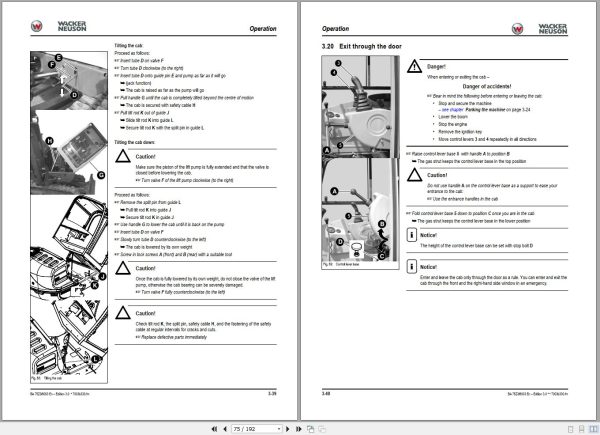
Exit through the door
Adjusting the left-hand side armrest
Towing the track excavator
Crane handling the machine
Loading and transporting the machine
Tying down the machine
Working with the machine
Control levers/ISO controls: overview
Changeover valve for SAE/ISO controls (option)
Control lever with proportional controls (option): overview
Control lever if equipped with 3rd control circuit (option): overview
Vario (option)
Re-equipping attachments
Powertilt (option)
Releasing the pressure on the work hydraulics
Grading
Safe load indicator (option)
Engine trouble
Malfunctions of the Powertilt unit
Engine error codes:
Introduction
Fuel system
Engine lubrication system
Engine and hydraulics cooling system
Air filter
V-belt
Hydraulic system
Pilot control filter
Tracks
Travelling drive
Electrical system
General maintenance work
Maintenance if the machine is out of service for a longer period of time
Fluids and lubricants
Maintenance plan (overview)
Maintenance label
Chassis
Engine
Undercarriage and swivel unit
Stabiliser blade
Work hydraulics
Fuse box on instrument panel up to serial nos. AD07209 (75Z3), AD07187 (8003)
Main fuse box with relays up to serial nos. AD07209 (75Z3)/AD07187 (8003)
Noise levels
Vibration
Fuse box on instrument panel from serial nos. AH00646 (75Z3)/AH00611 (8003)
Main fuse box with relays from serial nos. AH00646 (75Z3)/AH00611 (8003)
ECU from serial nos. AH00646 (75Z3)/AH00611 (8003)
Coolant compound table
Powertilt
Dimensions model 75Z³
Dimensions model 8003
Lift capacity table 75Z³
Lift capacity table 75Z³ counterweight (option)
Lift capacity table 75Z³ long stick (option)
Lift capacity table 75Z³ long stick, counterweight (option)
Lift capacity table 8003
Lift capacity table 8003 counterweight (option)
Lift capacity table 8003 long stick (option)
Lift capacity table 8003 long stick, counterweight (option)
Lift capacity table 8003 long stick, triple articulation boom (option)
Lift capacity table 8003 long stick, triple articulation boom, counterweight (option)
Lift capacity table 8003 triple articulation boom (option)
Lift capacity table 8003 triple articulation boom, counterweight (option)
Lift capacity table 8003 Vario (option)
Symbole
A
B
C
D
F
H
I
L
M
N
O
P
R
S
T
V
W
1 Introduction
1.1 Important information on this Operator’s Manual
1.2 Machine overview
1.3 Brief description
Travelling drive
Work hydraulics
Cooling system
Cab (ROPS, TOPS and FOPS)
1.4 Fields of application, attachments
Use: attachment
1.5 Regulations
1.6 EC declaration of conformity version 75Z³ and 8003 up to serial number AH
1.7 EC declaration of conformity version 75Z³ and 8003 from serial number AH
1.8 Type labels and component numbers
1.9 Other signs and symbols
…on the outside of the machine
…inside the cab
1.10 Fire extinguisher
2 Safety instructions
2.1 Identification of warnings and dangers
2.2 Warranty
2.3 Designated use and exemption from liability
2.4 General conduct and safety instructions
Organisational measures
Selection and qualification of staff, basic responsibilities
2.5 Safety instructions regarding operation
Normal operation
Applications with lifting gear
Trailers and attachments
Transport
2.6 Safety instructions for maintenance
2.7 Warning of special hazards
Electrical energy
Gas, dust, steam, smoke
Hydraulics
Noise
Oil, grease and other chemical substances
Battery
Tracks
3 Operation
3.1 75Z3/8003 cab
Up to serial number AH
From serial number AH
3.2 75Z3/8003 control elements
3.3 Putting into operation
Safety instructions
Putting the machine into operation for the first time
Running-in period
Check lists
Start-up checklist
Operation checklist
Parking checklist
3.4 Driving the excavator
Preheating start switch
Throttle
3.5 Automatic revs setting (option)
3.6 Telltales and warning lights: overview
Before starting the engine
Starting the engine: general
Procedure
Jump-starting the engine (supply battery)
Special instructions for driving on public roads
Starting at low temperatures
When the engine has started …
Engine warm-up
Moving off
Drive levers
High speed
Hydraulic brake
Mechanical brake
3.7 Driving on slopes
Specific safety instructions
Driving on slopes
Stabiliser blade operation
Parking the machine
Parking the machine on slopes
3.8 Light system
Working lights
Roof lights (option)
Interior light
Rotating beacon (option)
3.9 Cab heating and ventilation
Summer/winter operation (up to serial number AD04617)
Heating controls (from serial number AD04618)
3.10 Washer system
Tank for washer system
3.11 Air conditioning (option)
Recirculated air mode
3.12 Seat adjustment
Weight adjustment
Height adjustment
Horizontal adjustment
Backrest adjustment
3.13 Seat belt
3.14 Emergency exit
3.15 Front window
3.16 Door
3.17 Engine cover
3.18 Battery master switch
3.19 Tilting the cab
3.20 Exit through the door
3.21 Adjusting the left-hand side armrest
3.22 Towing the track excavator
Towing
3.23 Crane handling the machine
3.24 Loading and transporting the machine
3.25 Tying down the machine
3.7 Working with the machine
General safety instructions
3.8 Control levers/ISO controls: overview
Left-hand side control lever
Boom swivel controls/triple articulation boom (option)
Lowering the boom with the engine stopped
Rotating the upper carriage
Swivel unit brake
3.9 Changeover valve for SAE/ISO controls (option)
Right-hand side control lever
Directional valve position
Directional valve
3.10 Control lever with proportional controls (option): overview
Function
Measures to be taken in case of malfunctions
Changeover between auxiliary hydraulics and boom swivel
Switching the status indicator on/off for auxiliary hydraulics/boom swivel
Operating the boom/auxiliary hydraulics
Hammer operation
Adjusting control response:
Characteristic curves – status indicator
Releasing pressure
3.11 Control lever if equipped with 3rd control circuit (option): overview
Boom swivel controls
3.12 Vario (option)
Vario operation
Driving across slopes with the Vario feature
Vario warning device
Working with the Vario feature
Improved reach with the Vario feature
3.13 Re-equipping attachments
Removing a bucket
Mounting a bucket
Quickhitch (option)
Hydraulic quickhitch (option)
Maintenance
Operation
3.14 Powertilt (option)
Re-equipping
Mounting the Powertilt unit
Removing the Powertilt unit
Port
Right-hand side control lever (Powertilt)
Enabling the 3rd control circuit
Connections for auxiliary hydraulics
Grab couplings
3.15 Releasing the pressure on the work hydraulics
Pressure release with proportional controls (option)
Attachments
“Hose burst valve†safety feature (option)
Working with the standard bucket
Inadmissible work
Excavator work position
Bucket position when digging
Excavating trenches
Loading
Grading
Excavating trenches sideways
3.16 Grading
Working alongside trenches
3.17 Safe load indicator (option)
4 Troubleshooting
4.1 Engine trouble
4.2 Malfunctions of the Powertilt unit
4.3 Engine error codes:
5 Maintenance
5.1 Introduction
5.2 Fuel system
Refuelling
Fuel-filling pump (option) up to serial no. AD07209 (75Z3)
Fuel-filling pump (option) from serial no. AH00646 (75Z3)
Stationary fuel pumps
Diesel fuel specification
Bleeding the fuel system
Fuel prefilter with water separator
5.3 Engine lubrication system
Checking the oil level
Filling up engine oil
5.4 Engine and hydraulics cooling system
Checking/filling up coolant
5.5 Air filter
Replacing the filter
5.6 V-belt
Checking V-belt tension
Retightening the V-belt
Checking the V-belt of the air conditioning system
Tightening the V-belt of the air conditioning system
5.7 Hydraulic system
Checking the hydraulic oil level
Filling up hydraulic oil
Important information for the use of biodegradable oil
5.8 Pilot control filter
Checking hydraulic pressure lines
5.9 Tracks
Checking track tension
Setting the tracks
5.10 Travelling drive
Checking the oil level and filling up oil
Draining oil
Maintenance of attachments
5.11 Electrical system
Service and maintenance work at regular intervals
Instructions concerning specific components
Alternator
Powertilt (option)
5.12 General maintenance work
Cleaning
General instructions for all areas of the machine
Inside the cab
Exterior of the machine
Engine compartment
Screw connections and attachments
Pivots and hinges
5.13 Maintenance if the machine is out of service for a longer period of time
Preparatory work before taking the machine out of service
Putting the machine into operation again
5.14 Fluids and lubricants
Additional oil change and filter replacement (hydraulics)
5.15 Maintenance plan (overview)
5.16 Maintenance label
Explanation of symbols on the maintenance label
6 Specifications
6.1 Chassis
6.2 Engine
6.3 Hydraulic system
6.4 Undercarriage and swivel unit
6.5 Stabiliser blade
6.6 Work hydraulics
6.7 Electrical system
6.8 Fuse box on instrument panel up to serial nos. AD07209 (75Z3), AD07187 (8003)
6.9 Main fuse box with relays up to serial nos. AD07209 (75Z3)/AD07187 (8003)
Relays
6.10 Noise levels
6.11 Vibration
6.12 Dimensions model 75Z³
6.13 Dimensions model
6.14 Lift capacity table 75Z³
6.15 Lift capacity table 75Z³ counterweight (option)
6.16 Lift capacity table 75Z³ long stick (option)
6.17 Lift capacity table 75Z³ long stick, counterweight (option)
6.18 Lift capacity table
6.19 Lift capacity table 8003 counterweight (option)
6.20 Lift capacity table 8003 long stick (option)
6.21 Lift capacity table 8003 long stick, counterweight (option)
6.22 Lift capacity table 8003 long stick, triple articulation boom (option)
6.23 Lift capacity table 8003 long stick, triple articulation boom, counterweight (option)
6.24 Lift capacity table 8003 triple articulation boom (option)
6.25 Lift capacity table 8003 triple articulation boom, counterweight (option)
6.26 Lift capacity table 8003 Vario (option)
6.17 Fuse box on instrument panel from serial nos. AH00646 (75Z3)/AH00611 (8003)
6.18 Main fuse box with relays from serial nos. AH00646 (75Z3)/AH00611 (8003)
6.19 ECU from serial nos. AH00646 (75Z3)/AH00611 (8003)
6.20 Coolant compound table
6.21 Powertilt
REALEASE :
REALEASE :

REALEASE :
REALEASE :

REALEASE :
14.07.2020
REALEASE :
14.07.2020

REALEASE :
REALEASE :

REALEASE :
12.18.2021
REALEASE :
12.18.2021
REALEASE :
REALEASE :

REALEASE :
01.11.2022
REALEASE :
01.11.2022

REALEASE :
REALEASE :
Automotive - Heavy Equipment - Truck & Bus - Forklift - Crane