
1 ITEMVIEW CART

Total: 200.00
Expert Support
Full Speed
100% Working
10 USD
Contents:
1 Introduction
1.1 Important information on the Operator’s Manual
1.2 Machine overview
1.3 Brief description
1.4 Fields of application, attachments
1.5 Regulations
1.6 EC declaration of conformity for all machines delivered before 29 December 2009
1.7 EC declaration of conformity for all machines delivered after 29 December 2009
1.8 Declaration of conformity for machines without CE mark on the type label
1.9 Type labels and component numbers
1.10 Signs and symbols (up to serial no. AH01658)
1.11 Signs and symbols (from serial no. AH01659)
1.12 Fire extinguisher
2 Safety instructions
2.1 Identification of warnings and dangers
2.2 Warranty
2.3 Disposal
2.4 Designated use and exemption from liability
2.5 General conduct and safety instructions
2.6 Selection and qualification of staff, basic responsibilities
2.7 Safety instructions regarding operation
2.8 Information on visibility
2.9 Cab and protective structures (from serial no. AJ02793)
2.10 Checks when reversing the machine
2.11 Trailer operation
2.12 Applications with lifting gear
2.13 Attachments
2.14 Safety instructions for maintenance
2.15 Warning of special hazards
2.16 Hammer operation
2.17 Transport and towing
3 Operation
3.1 Cab 75Z3/8003 (up to serial no. AH00610)
3.2 Control elements 75Z3/8003 (up to serial no. AH00610)
3.3 Cab 75Z3/8003 (serial nos. AH00611 to AH02749)
3.4 Control elements 75Z3/8003 (serial nos. AH00611 to AH02749)
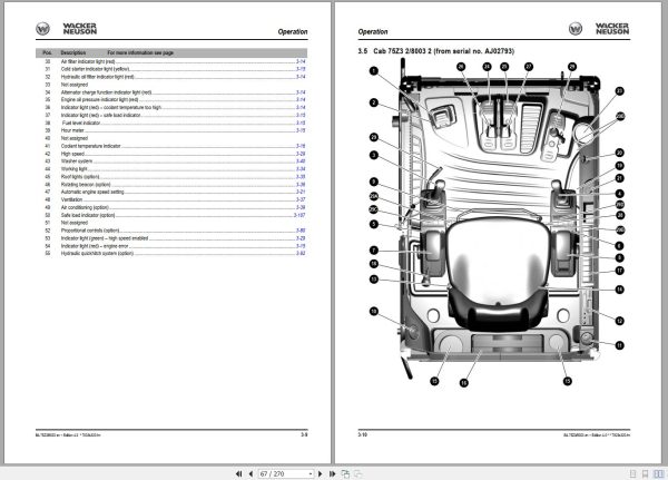
3.5 Cab 75Z3 2/8003 2 (from serial no. AJ02793)
3.6 Control elements 75Z3 2/8003 2 (from serial no. AJ02793)
3.7 Indicator lights and warning lights: overview
3.8 Putting into operation
3.9 Driving the machine
3.10 Automatic engine speed setting
3.11 Before starting the engine
3.12 Starting with the drive interlock (option)
3.13 Jump-starting the engine (supply battery)
3.14 Starting at low temperatures
3.15 When the engine has started
3.16 Special instructions for driving on public roads
3.17 Working on slopes
3.18 Stabiliser blade operation
3.19 Parking the machine
3.20 Light system
3.21 Cab heating and ventilation
3.22 Air conditioning (option)
3.23 Wiper/wash system
3.24 Seat (standard)
3.25 Seat (air suspension option)
3.26 Seat belt
3.27 Retracting lap belt (option)
3.28 Mirrors (option)
3.29 Emergency exit
3.30 Front window (up to serial no. AD06526)
3.31 Front window (from serial no. AD06527)
3.32 Opening the side window
3.33 Engine cover
3.34 Battery master switch
3.35 Tilting the cab
3.36 Door
3.37 Exit through the door (up to serial no. AH02749)
3.38 Exit through the door (from serial no. AJ02793)
3.39 Armrest adjustment (75Z3/8003 up to serial no. AH02749)
3.40 Armrest adjustment (75Z3/8003 from serial no. AJ02793)
3.41 Towing the machine
3.42 Crane handling the machine
3.43 Loading and transporting the machine
3.44 Tying down the machine
3.45 Driving signal (option)
3.46 Working with the machine
3.47 Control levers/ISO controls: overview
3.48 Changeover valve for SAE/ISO controls (option)
3.49 Control lever with proportional controls (option): overview
3.50 Control lever if equipped with 3rd control circuit (option): overview
3.51 Vario (8003 option)
3.52 Releasing the pressure on the work hydraulics
3.53 Re-equipping attachments
3.54 Quickhitch (option)
3.55 Hydraulic quickhitch – Easy Lock (option)
3.56 Powertilt (option)
3.57 Connections for auxiliary hydraulics
3.58 Safe load indicator (option)
3.59 Safety feature “Hose burst valve†(option)
3.60 Applications with lifting gear
3.61 Work area assessment and preparation
3.62 Working with the machine
3.63 Grading
3.64 Increased volume of auxiliary hydraulics 8003 (from serial no. AJ02782)
4 Troubleshooting
4.1 Troubleshooting the engine
4.2 Engine error codes:
4.3 Malfunctions of the Powertilt unit
4.4 Troubleshooting the central lubrication system (option)
4.5 Proportional controls (option) diagnosis display
5 Maintenance
5.1 Introduction
5.2 Safety-relevant parts
5.3 Fuel system
5.4 Engine lubrication system
5.5 Engine and hydraulics cooling system
5.6 Air filter
5.7 Change cab air filter
5.8 Replacing the filter element of the air conditioning system (option)
5.9 Diesel particulate filter (option)
5.10 V-belt
5.11 Hydraulic system
5.12 Tracks
5.13 Travelling drive
5.14 Maintenance of attachments
5.15 Electrical system
5.16 General maintenance work
5.17 Overview of lubrication points
5.18 Central lubrication system (option)
5.19 Preparatory work before taking the machine out of service
5.20 Maintenance if the machine is out of service for a longer period of time
5.21 Fluids and lubricants
5.22 Maintenance plan (overview)
5.23 Maintenance label
6 Specifications
6.1 Chassis
6.2 Engine
6.3 Hydraulic system
6.4 Work hydraulics
6.5 Undercarriage and swivel unit
6.6 Stabiliser blade
6.7 Electrical system
6.8 ECU control unit (75Z3/8003 from serial no. AH00646/AH00611)
6.9 Noise levels
6.10 Vibration
6.11 Coolant compound table
6.12 Powertilt
6.13 Weight indications
6.14 Dimensions model 75Z3
6.15 Dimensions model 8003 Vario (option)
6.16 Dimensions model 8003 triple articulation boom (option)
6.17 Lift capacity table 75Z3
6.18 Lift capacity table 75Z3 counterweight (option)
6.19 Lift capacity table 75Z3 long stick (option)
6.20 Lift capacity table 75Z3 long stick, counterweight (option)
6.21 Lift capacity table 8003
6.22 Lift capacity table 8003 counterweight (option)
6.23 Lift capacity table 8003 long stick (option)
6.24 Lift capacity table 8003 long stick, counterweight (option)
6.25 Lift capacity table 8003 triple articulation boom (option)
6.26 Lift capacity table 8003 triple articulation boom, counterweight (option)
6.27 Lift capacity table 8003 long stick, triple articulation boom (option)
6.28 Lift capacity table 8003 long stick, triple articulation boom, counterweight (option)
6.29 Lift capacity table 8003 Vario (option)
REALEASE :
REALEASE :

REALEASE :
14.07.2020
REALEASE :
14.07.2020

REALEASE :
REALEASE :

REALEASE :
01.11.2022
REALEASE :
01.11.2022

REALEASE :
REALEASE :

REALEASE :
REALEASE :
REALEASE :
REALEASE :

REALEASE :
12.18.2021
REALEASE :
12.18.2021
 Automotive - Heavy Equipment - Truck & Bus - Forklift - Crane