
0 ITEMSVIEW CART

✓
Expert Support
✓
Full Speed
✓
100% Working
Wacker Neuson Mobile Generator G 85 Repair Manual 330564592
Size: 12.27 MB
Format: PDF
Language: English
Brand: Wacker Neuson
Type of Machine: Mobile Generator
Type of Manual: Repair Manual
Model: Wacker Neuson G 85 Mobile Generator
Part Number: 330564592
Publication Date: 2009
Number of Pages: 130 Pages
30 USD
- Description
Description
Contents:
Mobile Generator
1 Safety Information
1.1 Operating Safety
1.2 Service Safety
1.3 Operator Safety while using Internal Combustion Engines
1.4 Towing Safety
1.5 Reporting Trailer Safety Defects
2 Theory of Operation
2.1 Basic Schematic
2.2 Introduction
2.3 Terminology
3 Electrical Testing Techniques
3.1 Checking Continuity
3.2 Checking Resistance
3.3 Checking Voltage
3.4 Probing ECM Plugs and Pins
4 ECM Background Information
4.1 ECM Handling Precaution
4.2 Normal Boot-up Sequence
4.3 Display Variables and Values
4.4 ECM Display Screens-Start Switch in Remote Position
4.5 Additional Variables Monitored by the ECM
4.6 Voltage Display Errors
4.7 ECM Automatic Engine Shutdown Conditions
4.8 ECM Circuit Boards
4.9 Control Wiring Numbering & Colors
4.10 Removing and Installing the ECM
5 ECM/Sensor Troubleshooting
6 John Deere Engines With ECU
6.1 John Deere Engines With ECU Background
6.2 Locations of Engine Electrical Components
6.3 Engine Electrical Components
7 Engine Starting Troubleshooting
8 Output Voltage Troubleshooting
9 Disassembly/Assembly Procedures
9.1 Tools
9.2 Ordering Parts
9.3 Reference Numbers ( )
9.4 Weight Block
9.5 Removing the Roof
9.6 Preparing Unit for Generator Removal
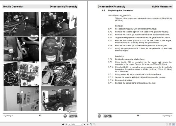
9.7 Replacing the Generator
9.8 Removing the AVR
9.9 Installing the AVR
9.10 Removing the Engine
9.11 Installing the Engine
9.12 Replacing the Fuel Tank
9.13 Replacing the Emergency Stop Switch (older)
9.14 Replacing the Emergency Stop Switch (newer)
9.15 Replacing the Diodes
9.16 Replacing the Voltage Selector Switch (VSS)
9.17 G 50, G 70, G 85 VSS Wiring
10 Technical Data
10.1 Engine Data
10.2 Generator Data
10.3 Trailer and Skid Data
10.4 Dimensions
10.5 Engine Wiring Diagram-John Deere with ECU
10.6 ECU Wiring Diagram
10.7 ECU Harness Connector
10.8 Generator Wiring Diagram
1 Safety Information
1.1 Operating Safety
1.2 Service Safety
1.3 Operator Safety while using Internal Combustion Engines
1.4 Towing Safety
1.5 Reporting Trailer Safety Defects
2 Theory of Operation
2.1 Basic Schematic
2.2 Introduction
2.3 Terminology
3 Electrical Testing Techniques
3.1 Checking Continuity
3.2 Checking Resistance
3.3 Checking Voltage
3.4 Probing ECM Plugs and Pins
4 ECM Background Information
4.1 ECM Handling Precaution
4.2 Normal Boot-up Sequence
4.3 Display Variables and Values
4.4 ECM Display Screens-Start Switch in Remote Position
4.5 Additional Variables Monitored by the ECM
4.6 Voltage Display Errors
4.7 ECM Automatic Engine Shutdown Conditions
4.8 ECM Circuit Boards
4.9 Control Wiring Numbering & Colors
4.10 Removing and Installing the ECM
5 ECM/Sensor Troubleshooting
Continue
Replace the fuse with one of the same size and rating.
Check the function of the main circuit breaker. The shunt of the main circuit breaker is most likely the cause of a fuse failure. See section 5.10 Checking the Main Circuit Breaker.
The fuses are OK.
Continued from the previous page.
6 John Deere Engines With ECU
6.1 John Deere Engines With ECU Background
6.2 Locations of Engine Electrical Components
6.3 Engine Electrical Components
7 Engine Starting Troubleshooting
Check the function of the main circuit breaker. The shunt of the main circuit breaker is most likely the cause of a fuse failure. See Section 7.7 Checking the Main Circuit Breaker.
Go to step 6.
Charge the battery.
Repair or replace wire #53.
Repair or replace wire #15.
The ECM is OK.
The ECM has failed. Call Wacker Neuson Service.
The emergency stop switch has failed; replace it.
The emergency stop switch is not the problem.
Repair or replace the red wire.
Repair or replace wire #422.
Repair or replace wire #050D or wire #14.
The starter relay is OK.
The starter relay has failed; replace it.
Repair or replace the large red wire.
Repair or replace small red wire.
Repair or replace red wire #11.
Repair or replace grey wire #65.
Repair or replace wire #14.
The intake heater relay is OK.
The intake heater relay has failed; replace it.
The main circuit breaker has failed; replace it.
Continue.
_____; _____; _____
The main circuit breaker is functioning properly.
8 Output Voltage Troubleshooting
The emergency stop switch is OK.
The lug door switch has failed; replace it.
Reconnect the blue and blue/white wires; then continue.
The lug door switch is OK.
The voltage adjusting rheostat has failed; replace it.
The voltage adjusting rheostat is OK.
Remove the vent cover from the generator and check the generator for damage.
Auxiliary winding is OK.
Remove the vent cover from the generator and check the generator for damage; then continue.
The excitor stator is OK.
The exciter stator has failed.
Call Wacker Neuson Service.
The sensing wires are OK.
The excitation system is functioning properly.
Check the exciter rotor winding. See Checking the Exciter Rotor Winding.
The main stator windings and the voltage selector switch are OK.
Replace all diodes.
The main rotor winding has failed.
The main rotor winding is OK.
The main rotor winding has failed. Call Wacker Neuson Service.
The exciter rotor windings are OK.
The exciter rotor has failed. Call Wacker Neuson
The main stator windings are OK. If there is a difference between the readings taken here and those taken at the lugs, the VSS has failed; replace it.
The main stator windings have failed. Call Wacker Neuson
9 Disassembly/Assembly
9.1 Tools
9.2 Ordering Parts
9.3 Reference Numbers ( )
9.4 Weight Block
9.5 Removing the Roof
9.6 Preparing Unit for Generator Removal
9.7 Replacing the Generator
9.8 Removing the AVR
9.9 Installing the AVR
9.10 Removing the Engine
9.11 Installing the Engine
9.12 Replacing the Fuel Tank
9.13 Replacing the Emergency Stop Switch (older)
9.14 Replacing the Emergency Stop Switch (newer)
9.15 Replacing the Diodes
9.16 Replacing the Voltage Selector Switch (VSS)
9.17 G 50, G 70, G 85 VSS Wiring
10 Technical Data
10.1 Engine Data
10.2 Generator Data
10.3 Trailer and Skid Data
10.4 Dimensions
10.5 Engine Wiring Diagram-John Deere with ECU
10.6 ECU Wiring Diagram
10.7 ECU Harness Connector
10.8 Generator Wiring Diagram
Sealants.pdf
Threadlockers and Sealants
Torque.pdf
Torque Values
Metric Fasteners (DIN)
Inch Fasteners (SAE)
Related Products
-
Wacker Neuson PDF DVD Collection Service Part & Operator Manual_EN
Original price was: 150.90Current price is: 90. USDWacker Neuson PDF DVD Collection Service Part & Operator Manual_ENSize: 731 MBFormat : PDFLanguage : EnglishBrand: Wacker NeusonNumber of page: 61 FolderAmount of DVD: 1 DVDWindow: All Window 32 an d 64 bitType of machine: Wacker Neuson Heavy EquipmentType of document: Service Part & Operator ManualHot-40%
REALEASE :
14.07.2020
REALEASE :
14.07.2020
-
Wacker Neuson Dumper 1501 D01-05 Spare Parts Catalog 1000165936
Original price was: 20.10Current price is: 10. USDSize: 12.09 MBFormat: PDFLanguage: English, German, FrenchBrand: Wacker NeusonType of Machine: DumperType of Manual: Parts ManualModel: Wacker Neuson 1501 D01-05 DumperPart Number: 1000165936Publication Date: 2016Number of Pages: 255 Pages-50%
REALEASE :
REALEASE :
-
Wacker Neuson Excavator Deere 26P Parts and Repair Service Manual
80 USDSize: 216.88 MBFormat: PDFLanguage: EnglishBrand: Wacker NeusonType of Machine: ExcavatorType of Manual: Repair Service Manual, Parts Manual, Electric and Hydraulic DiagramsModel: Wacker Neuson Deere 26P Excavator
REALEASE :
REALEASE :
-
Wacker Neuson Track Excavator EZ17 Parts and Operation Service Manual
80 USDSize: 134.58 MBFormat: PDFLanguage: EnglishBrand: Wacker NeusonType of Machine: Track ExcavatorType of Manual: Service Manual, Operation Manual, Parts Manual, Electric and Hydraulic DiagramsModel: Wacker Neuson EZ17 Track Excavator
REALEASE :
REALEASE :
-
Wacker Neuson 4.91GB PDF DVD Collection Service Part Diagrams Assembly & Operator Manual
Original price was: 200.140Current price is: 140. USDWacker Neuson 4.91GB PDF DVD Collection Service Part Diagrams Assembly & Operator ManualSize: 4.91 GB (Unpack)Format : PDFLanguage : English, German, FranceBrand: Wacker NeusonNumber of Folder: 1,293 Files, 188 FoldersAmount of DVD: 1 DVDWindow: All Window 32 and 64 bitType of machine: Wacker Neuson Heavy Equipment– Wacker Neuson Dumper– Wacker Neuson Excavator– Wacker Neuson Skid Steer Loader– Wacker Neuson Roller– Wacker Neuson Telehandler…Type of document:– Service Manual– Operating Manual– Spare Part List (English, German, France Langues)– Diagrams– Service News– Assembly InstructionsHigh-Speed link downloadHot-30%
REALEASE :
12.18.2021
REALEASE :
12.18.2021
-
Wacker Neuson Track Excavator 803 803 Dualpower Service Manual 1000164843
20 USDSize: 9.90 MBFormat: PDFLanguage: EnglishBrand: Wacker NeusonType of Machine: Track ExcavatorType of Manual: Service Manual, Hydraulic and Electric DiagramsModel: Wacker Neuson 803, 803 Dualpower Track ExcavatorOrder Number: 1000164843Number of Pages: 196 Pages
REALEASE :
REALEASE :
-
Wacker Neuson 23.1GB PDF Part Manual, Operator Manual, Repair Manual & Wiring Diagram DVD
Original price was: 400.240Current price is: 240. USDWacker Neuson 23.1GB PDF Part Manual, Operator Manual, Repair Manual & Wiring Diagram DVDSize: 23.1 Gb (PDF Files)Language: EnglishFormat: PDFBrand: Wacker NeusonOS: All WindowsQuantity of CD: 1 DVDHigh-Speed link DownloadType of document: Part Manual, Operator Manual, Repair Manual, Electric Diagram, Hydraulic DiagramHot-40%
REALEASE :
01.11.2022
REALEASE :
01.11.2022
-
Wacker Neuson Track Excavator EZ26 Operation Service Manual
60 USDSize: 172.34 MBFormat: PDFLanguage: EnglishBrand: Wacker NeusonType of Machine: Track ExcavatorType of Manual: Service Manual, Operation Manual, Electric and Hydraulic DiagramsModel: Wacker Neuson EZ26 Track Excavator
REALEASE :
REALEASE :