
0 ITEMSVIEW CART


✓
Expert Support
✓
Full Speed
✓
100% Working
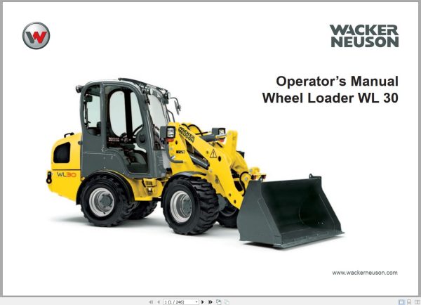
Wacker Neuson Wheel Loader WL30 Operating Manual 231820729
Size: 4.09 MB
Format: PDF
Language: English
Brand: Wacker Neuson
Type of Machine: Wheel Loader
Type of Manual: Operating Manual
Model: Wacker Neuson WL30 Wheel Loader
Part Number: 231820729
Publication Date: 2010
Number of Pages: 246 Pages
10 USD
- Description
Description
Contents:
PREFACE
1 BASIC INFORMATION
1.1 Notes about this Operator’s Manual
1.2 Explanation of the symbols used in this Operator’s Manual
1.3 Warranty and liability
1.4 Intended use
2 BASIC SAFETY INSTRUCTIONS
2.1 Organizational measures
2.2 Selection and qualification of personnel / basic duties
2.3 Safety instructions for certain operating phases
2.4 Safety instructions for particular hazards
2.5 Transporting and towing / restarting
2.6 Final decommissioning / dismantling
2.7 Safety labels used
2.8 Safety devices
3 TECHNICAL DATA
3.1 Technical description
3.2 Loader data
3.3 Product identification number plates
3.4 Dimensions
4 DESCRIPTION OF THE INDICATOR, WARNING AND CONTROL ELEMENTS
4.1 Operating elements and instruments
4.2 Control and warning indicator lights
4.3 Switches / rocker switches
4.4 Indicator devices
5 OPERATING AND OPERATION
5.1 Before starting up
5.2 Starting up
5.3 Propulsion operation
5.4 Work operation
5.5 Optional equipment
6 TOWING AND TRANSPORTING
6.1 Towing
6.2 Transporting
7 Lowering loader arms
8 Relieving RESIDUAL PRESSURE IN THE HYDRAULIC SYSTEM
9 SECURING THE LOADER
10 SERVICING AND INSPECTION
10.1 Basic safety instructions for servicing and inspection
10.2 Servicing and inspection intervals
10.3 Lubrication schedule
10.4 Cleaning the loader
10.5 General safety check
10.6 Specifications and filling quantities
10.7 Maintenance and inspection work
10.8 Jump-starting / emergency starting
10.9 Loader storage
11 Troubleshooting and emergency maintenance
12 Safety instructions for repairs
12.1 General safety regulations for repairs
12.2 Engine
12.3 Welding work
12.4 Hydraulic system
12.5 Brakes
13 FINAL SHUTDOWN OF THE LOADER / DECOMMISSIONING
14 Appendix
14.1 Ordering replacement parts
14.2 Inspection verification
Index
List of figures
Activating the optional hydraulics
Activating the optional hydraulics using the button
Activating the optional hydraulics using the control lever
Adding engine oil
Adding hydraulic fluid
Adjusting the operator’s seat
Adjusting the steering column
Air filter dust valve
Air pressure table for tires
Articulation frame lock
Battery
Braking and stopping
Changing attachments
Changing speeds
Changing the axle oil
Changing the coolant
Changing the engine oil
Changing the engine oil filter
Changing the fuel pre-filter
Changing the hydraulic fluid
Changing the main fuel filter
Changing the return filter element
Changing the travel direction
Changing travel directions
Changing wheels
Checking / changing the safety filter
Checking the antifreeze mix
Checking the axle oil level
Checking the brake fluid level / adding brake fluid
Checking the coolant level / refilling the coolant
Checking the engine oil level
Checking the hydraulic fluid level
Check main air filter element / clean / replace
Cleaning the cooling system
Coupling of attachments
Daily servicing
Depressurized return line
Description of the indicator, warning and control elements
Detent mechanism for the optional hydraulics
Differential lock
Dimensions
Disconnecting the drive (Bypass- switching)
Each time before starting work
Electrical connector on the loader lift arms
Filling the container for the windshield washer system
First inspection after 50 operating hours
Fueling
Fuse allocation
Headlights and rotating beacon
Hydraulic fluid cooler
If the engine does not start
Independent driving onto the transport device
Inflating the tires
Inspection after 500 operating hours
Inspection intervals
Jump-starting / emergency starting
Lighting system and forward warning device
Loader data
Loader lift arm damping
Loader lift arms locking system
Loader Tie-Down
Loader travel
Loading on a transport vehicle
Loading with crane
Lubrication schedule
Operating lever for Loader lift arms
Optional hydraulics control activation
ROPS / FOPS – protective structures
Safety belt
Servicing the air filter system
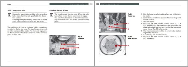
Servicing the axles
Servicing the battery
Servicing the brakes
Servicing the cooling system
Servicing the electrical system
Servicing the engine
Servicing the fuel system
Servicing the hydraulic system
Servicing the tires and wheels
Servicing the water separator
Specifications and filling quantities
Starting the engine
Technical descriptions
Tilting the operator’s platform
Tip-overs
Towing equipment
Troubleshooting and emergency maintenance
Troubleshooting for the loader
Troubleshooting for transmission pump / oil engine
Uncoupling attachments
Ventilation filter / hydraulic fluid filler neck
Venting the fuel system
Venting the hydraulic system
Weekly servicing
Wipers and windshield washer system
Working with the bucket
Fig. 1 Document pocket
Fig. 2 Transport of large bales or packaged goods
Fig. 3 Location of the Safety labels
Fig. 4 Fire extinguisher
Fig. 5 Attaching the rotating beacon
Fig. 6 Seat belt
Fig. 7 Emergency exit
Fig. 8 Battery disconnect switch
Fig. 9 Lever for the locking mechanism of the Loader lift arm
Fig. 10 Vehicle ID
Fig. 11 Dimensions
Fig. 12 Operating elements
Fig. 13 Control and warning lights
Fig. 14 Switches / rocker switches (1)
Fig. 15 Switches / rocker switches (2)
Fig. 16 Indicator devices
Fig. 17 Fuel filler neck
Fig. 18 Cab door locking
Fig. 19 Releasing locked cab doors
Fig. 20 Adjusting the steering column
Fig. 21 Adjusting the operator’s seat
Fig. 22 Buckling the seat belt
Fig. 23 Adjusting the seat belt
Fig. 24 Lighting / forward warning device
Fig. 25 Switches for windshield wipers
Fig. 26 Location of the windshield washer container
Fig. 27 Headlight and rotating beacon switches
Fig. 28 Heating controller
Fig. 29 Ventilation outlets
Fig. 30 Starting switch
Fig. 31 Changing direction
Fig. 32 Operating lever for loader lift arms
Fig. 33 Operating lever for the optional hydraulics
Fig. 34 Hydraulic connections
Fig. 35 Button for optional hydraulics
Fig. 36 Depressurized return line
Fig. 37 Lever for the locking mechanism of the loader lift arms
Fig. 38 Switch for differential lock
Fig. 39 Coupling and uncoupling tools
Fig. 40 Control lever movements
Fig. 41 Level indicator
Fig. 42 Loading work 1
Fig. 43 Loading work 2
Fig. 44 Loading work 3
Fig. 45 Excavation work 4
Fig. 46 Excavation work 5
Fig. 47 Switch for loader lift arm vibration damping
Fig. 48 Optional hydraulics control lever
Fig. 49 Electrical connector on the loader lift arms
Fig. 50 Switch for the electrical connector on the loader lift arms
Fig. 51 Towing equipment
Fig. 52 Disconnecting the drive
Fig. 53 Articulation frame lock
Fig. 54 Attachment point label
Fig. 55 Attachment points
Fig. 56 Tie down point label
Fig. 57 Tie down points
Fig. 58 Tying down the loader
Fig. 59 Reducing residual pressure
Fig. 60 Load holding control valve
Fig. 61 Points of lubrication
Fig. 62 Handle for the engine enclosure
Fig. 63 Cab tilt lever
Fig. 64 Position of the cab mounting bolts
Fig. 65 Cab safety support
Fig. 66 Checking the engine oil / filling the oil
Fig. 67 Engine oil drain opening
Fig. 68 Location of the engine oil filter
Fig. 69 Engine oil filter
Fig. 70 Water separator
Fig. 71 Fuel pre-filter, main fuel filter
Fig. 72 Changing the main fuel filter
Fig. 73 Venting the fuel system
Fig. 74 Location of the air filter
Fig. 75 Air filter elements
Fig. 76 Radiator
Fig. 77 Engine temperature sensor
Fig. 78 Hydraulic oil temperature sensor
Fig. 79 Radiator opening
Fig. 80 Checking the antifreeze mix
Fig. 81 Cleaning the cooling system
Fig. 82 Hydraulic fluid cooler
Fig. 83 Ventilation filter
Fig. 84 Hydraulic fluid dip stick
Fig. 85 Hydraulic fluid drain plugs
Fig. 86 Return filter
Fig. 87 Filter insert
Fig. 88 Differential
Fig. 89 Transfer case
Fig. 90 Wheel reduction
Fig. 91 Cab vent filter
Fig. 92 Brake fluid container
Fig. 93 Master fuse
Fig. 94 Fuse boxes
Fig. 95 Fuse allocation
Fig. 96 Location of the battery
Fig. 97 Servicing the battery
Fig. 98 Removing the battery
Fig. 99 Connecting the jumper cables
Related Products
-
Wacker Neuson 23.1GB PDF Part Manual, Operator Manual, Repair Manual & Wiring Diagram DVD
Original price was: 400.240Current price is: 240. USDWacker Neuson 23.1GB PDF Part Manual, Operator Manual, Repair Manual & Wiring Diagram DVDSize: 23.1 Gb (PDF Files)Language: EnglishFormat: PDFBrand: Wacker NeusonOS: All WindowsQuantity of CD: 1 DVDHigh-Speed link DownloadType of document: Part Manual, Operator Manual, Repair Manual, Electric Diagram, Hydraulic DiagramHot-40%
REALEASE :
01.11.2022
REALEASE :
01.11.2022
-
Wacker Neuson Dumper 1501 D01-05 Spare Parts Catalog 1000165936
Original price was: 20.10Current price is: 10. USDSize: 12.09 MBFormat: PDFLanguage: English, German, FrenchBrand: Wacker NeusonType of Machine: DumperType of Manual: Parts ManualModel: Wacker Neuson 1501 D01-05 DumperPart Number: 1000165936Publication Date: 2016Number of Pages: 255 Pages-50%
REALEASE :
REALEASE :
-
Wacker Neuson Track Excavator 803 803 Dualpower Service Manual 1000164843
20 USDSize: 9.90 MBFormat: PDFLanguage: EnglishBrand: Wacker NeusonType of Machine: Track ExcavatorType of Manual: Service Manual, Hydraulic and Electric DiagramsModel: Wacker Neuson 803, 803 Dualpower Track ExcavatorOrder Number: 1000164843Number of Pages: 196 Pages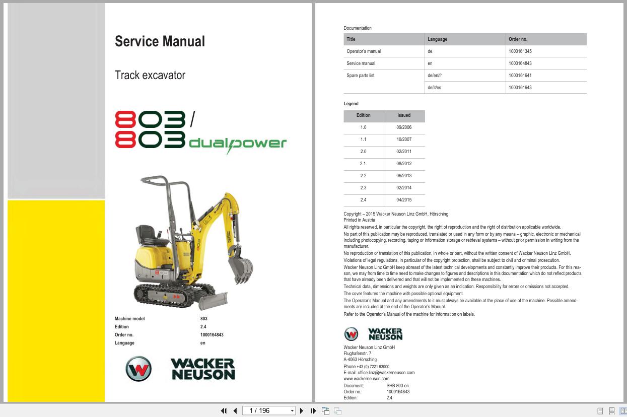
REALEASE :
REALEASE :
-
Wacker Neuson PDF DVD Collection Service Part & Operator Manual_EN
Original price was: 150.90Current price is: 90. USDWacker Neuson PDF DVD Collection Service Part & Operator Manual_ENSize: 731 MBFormat : PDFLanguage : EnglishBrand: Wacker NeusonNumber of page: 61 FolderAmount of DVD: 1 DVDWindow: All Window 32 an d 64 bitType of machine: Wacker Neuson Heavy EquipmentType of document: Service Part & Operator ManualHot-40%
REALEASE :
14.07.2020
REALEASE :
14.07.2020
-
Wacker Neuson Excavator Deere 26P Parts and Repair Service Manual
80 USDSize: 216.88 MBFormat: PDFLanguage: EnglishBrand: Wacker NeusonType of Machine: ExcavatorType of Manual: Repair Service Manual, Parts Manual, Electric and Hydraulic DiagramsModel: Wacker Neuson Deere 26P Excavator
REALEASE :
REALEASE :
-
Wacker Neuson 4.91GB PDF DVD Collection Service Part Diagrams Assembly & Operator Manual
Original price was: 200.140Current price is: 140. USDWacker Neuson 4.91GB PDF DVD Collection Service Part Diagrams Assembly & Operator ManualSize: 4.91 GB (Unpack)Format : PDFLanguage : English, German, FranceBrand: Wacker NeusonNumber of Folder: 1,293 Files, 188 FoldersAmount of DVD: 1 DVDWindow: All Window 32 and 64 bitType of machine: Wacker Neuson Heavy Equipment– Wacker Neuson Dumper– Wacker Neuson Excavator– Wacker Neuson Skid Steer Loader– Wacker Neuson Roller– Wacker Neuson Telehandler…Type of document:– Service Manual– Operating Manual– Spare Part List (English, German, France Langues)– Diagrams– Service News– Assembly InstructionsHigh-Speed link downloadHot-30%
REALEASE :
12.18.2021
REALEASE :
12.18.2021
-
Wacker Neuson Track Excavator EZ17 Parts and Operation Service Manual
80 USDSize: 134.58 MBFormat: PDFLanguage: EnglishBrand: Wacker NeusonType of Machine: Track ExcavatorType of Manual: Service Manual, Operation Manual, Parts Manual, Electric and Hydraulic DiagramsModel: Wacker Neuson EZ17 Track Excavator
REALEASE :
REALEASE :
-
Wacker Neuson Track Excavator EZ26 Operation Service Manual
60 USDSize: 172.34 MBFormat: PDFLanguage: EnglishBrand: Wacker NeusonType of Machine: Track ExcavatorType of Manual: Service Manual, Operation Manual, Electric and Hydraulic DiagramsModel: Wacker Neuson EZ26 Track Excavator
REALEASE :
REALEASE :