
0 ITEMSVIEW CART


✓
Expert Support
✓
Full Speed
✓
100% Working
Wacker Neuson Wheel Loader WL57 Operating Manual 1000289675
Size: 9.86 MB
Format: PDF
Language: English
Brand: Wacker Neuson
Type of Machine: Wheel Loader
Type of Manual: Operating Manual
Model: Wacker Neuson WL57 Wheel Loader
Part Number: 1000289675
Publication Date: 2014
Number of Pages: 312 Pages
10 USD
- Description
Description
Contents:
Preface
1 BASIC INFORMATION
1.1 Notes about this operator’s manual
1.2 Explanation of the symbols used in this operator’s manual
1.3 Warranty and liability
1.4 Proper use
2 BASIC SAFETY INSTRUCTIONS
2.1 Organizational measures
2.2 Personnel selection and qualifications/general duties and obligations
2.3 Safety instructions for particular phases of operation
2.4 Safety instructions for special types of hazard
2.5 Transporting and towing/restarting
2.6 Final decommissioning/dismantling
2.7 Safety stickers used
2.8 Safety devices
3 TECHNICAL DATA
3.1 Technical description
3.2 Loader data
3.3 Lifting diagram
3.4 Identification plates
3.5 Dimensions
4 DESCRIPTION OF THE INDICATOR, WARNING AND OPERATING ELEMENTS
4.1 Operating elements and instruments
4.2 Indicator lamps and warning lamps
4.3 Indicator devices
4.4 Toggle switches
4.5 Switches / rotary switches
5 CONTROLS AND OPERATION
5.1 Before starting up
5.2 Starting up
5.3 Driving mode
5.4 Work operation
5.5 Optional equipment
5.6 Safety instructions for trailer operation
6 TOWING AND TRANSPORTING
6.1 Towing
6.2 Transporting
7 Measures in the event of power loss
8 RELIEVING RESIDUAL PRESSURE IN THE HYDRAULIC SYSTEM
9 SECURING THE LOADER
10 SERVICING AND INSPECTION
10.1 Basic safety instructions for servicing and inspection
10.2 Servicing and inspection intervals
10.3 Lubrication schedule
10.4 Cleaning the loader
10.5 General safety check
10.6 Specifications and filling quantities
10.7 Maintenance and inspection work
10.8 Emergency starting / jump-starting
10.9 Shutting down and restarting the loader
11 TROUBLESHOOTING AND EMERGENCY MAINTENANCE
12 SAFETY INSTRUCTIONS FOR REPAIRS
12.1 General safety regulations for repairs
12.2 Engine
12.3 Welding work
12.4 Hydraulic system
12.5 Brakes
13 FINAL SHUTDOWN OF THE LOADER / DECOMMISSIONING
14 APPENDIX
Ordering replacement parts
Index
List of figures
A
Activating the optional hydraulics
Adding engine oil
Adjusting the distance between the fork prongs
Adjusting the driver’s seat
Adjusting the seat belt
Adjusting the steering column
Air conditioning system
Air filter dust valve
Air pressure table for tires
B
Battery
Before every start of work
Bleeding the hydraulic system
Blocking the articulated joint
Braking and stopping
C
Change in direction of travel
Changeover valve applies tilting in/out function to additional hydraulics
Changing attachments
Changing the axle oil
Changing the coolant
Changing the engine oil
Changing the engine oil filter
Changing the hydraulic fluid
Changing the return filter element
Changing wheels
Checking / changing the safety air filter
Checking the antifreeze mix
Checking the axle oil level
Checking the brake fluid level / adding brake fluid
Checking the coolant level / adding coolant
Checking the engine oil level
Checking the hydraulic fluid level
Checking V-belt tension / Tensioning the V-belt
Check main air filter element / clean / replace
Cleaning the cooling system
Cleaning the cooling system if the loader is equipped with air conditioning
Control lever for the lift frame
Coupling and uncoupling the connections for additional hydraulics
Coupling attachments
D
Daily servicing
Depressurized return line
Description of the engine error display warning lights for the loader WL57
Description of the indicator, warning and operating elements
Description of the starting process
Detent mechanism for the control lever for the additional hydraulics
Differential pawl
Dimensions
Disconnecting/connecting the battery / replacing the battery
Doors and Windows
Driving direction switch
Driving off with the loader
Driving the loader onto a transport vehicle under its own power
E
EC Declaration of Conformity
Electrical connector on the loader lift arms
Emergency starting / jump-starting
Exhausting the fuel system
F
Fastening the seat belt
Filling the container for the windshield washer system
Filling up with hydraulic fluid
Front headlights:
Fuel system (Deutz engine)
Fuel system (Perkins engine)
Fuse allocation
H
Headlights and rotating beacon
Heating and ventilation in the driver’s cab
„High Flow†hydraulic connection
Hydraulic connections at the rear
Hydraulic fluid cooler
Hydraulic locking mechanism for attachments
Hydro connection additionally via changeover valve
I
If the engine does not start
Inflating the tires
Inspection after 30 operating hours (first inspection)
Inspection after 500 operating hours
Inspection intervals
L
Lengthening the seat belt
Level indicator
Lifting diagram
Lighting system and forward warning device
Loader data
Loader lift arm damping
Loading the loader onto a transport vehicle
Loading with a crane
Locking mechanism for the lift frame
Lubrication schedule
M
Maintenance of the air filter system
Maintenance of the axles
Maintenance of the battery
Maintenance of the brakes
Maintenance of the cooling system
Maintenance of the electrical system
Maintenance of the engine
Maintenance of the fuel system
Maintenance of the hydraulic system
Monitoring the stability of the loader
O
Optional multi- function lever for multiple functions
R
Rear headlights:
Rear window heating
Refueling
Releasing the seat belt
S
Seat belt
Servicing the air conditioning system
Servicing the cab vent filter
Servicing the tyres and wheels
Short-circuiting the drive
Shortening the seat belt
Specifications and fill quantities
Starting the engine
Switching gears
T
Technical description of the loader
The rotating beacon
Tilting the driver‘s platform
Towing equipment
Troubleshooting and emergency maintenance
Troubleshooting for the loader
Troubleshooting for transmission pump / oil engine
Tying down the loader
U
Uncoupling attachments
Uncoupling the trailer from the machine
V
Ventilation filter / hydraulic fluid filler neck
Vibrations (weighted effective value)
W
Weekly servicing
What to do if the loader tips over
Windshield wipers and windshield washer system
Working with the bucket
Working with the pallet fork
Working with the telescopable lift frame
Fig. 1 Document pocket
Fig. 2 Transport of large bales or packaged goods
Fig. 3 Safety stickers
Fig. 4 Fire extinguisher
Fig. 5 Mounting for rotating beacon
Fig. 6 Load holding control valve
Fig. 7 Battery disconnect switch
Fig. 8 Seat belt
Fig. 9 Emergency exit
Fig. 10 Switch for lift frame arrest
Fig. 11 Lifting diagram
Fig. 12 Vehicle identification number
Fig. 13 Standard dimensions
Fig. 14 Dimensions of telescopable lift frame
Fig. 15 Operating elements
Fig. 16 Control and warning lights
Fig. 17 Control and warning lights
Fig. 18 Indicator devices
Fig. 19 Stability of the loader
Fig. 20 Toggle switches 1
Fig. 21 Toggle switches 2
Fig. 22 Toggle switches 3
Fig. 23 Rotary switch
Fig. 24 Fuel tank filler neck
Fig. 25 Entering
Fig. 26 Cab door lock
Fig. 27 Window lock
Fig. 28 Side window locking mechanism
Fig. 29 Door arrest
Fig. 30 Release door arrest
Fig. 31 Door put-up hinges
Fig. 32 Adjusting the operator’s seat
Fig. 33 Adjusting the steering column
Fig. 34 Fastening the seat belt
Fig. 35 Adjusting the seat belt
Fig. 36 Lighting / forward warning device
Fig. 37 Switches for windshield wipers
Fig. 38 Switches for the headlights and rotating beacon
Fig. 39 Heating controller
Fig. 40 Ventilation outlets
Fig. 41 Rocker switch for air conditioning system
Fig. 42 Ignition key
Fig. 43 Operating lever for parking brake
Fig. 44 Gear changer/gear shift
Fig. 45 Operating lever for loader lift arms
Fig. 46 Telescoping button
Fig. 47 Stability indicator
Fig. 48 Payload sticker
Fig. 49 Switch for lift frame arrest
Fig. 50 Control lever for the additional hydraulics
Fig. 51 Connections for the additional hydraulics
Fig. 52 Releasing the hydraulic locking mechanism for attachments
Fig. 53 Coupling the hydraulic locking mechanism
Fig. 54 Switch to relieve pressure
Fig. 55 Connecting the additional hydraulics
Fig. 56 Uncoupling – hydraulic locking mechanism
Fig. 57 Control lever movements
Fig. 58 Level indicator
Fig. 59 Loading work 1
Fig. 60 Loading work 2
Fig. 61 Loading work 3
Fig. 62 Excavation work 4
Fig. 63 Excavation work 5
Fig. 64 Correct distance between the fork prongs
Fig. 65 Adjusting the distance between the fork prongs
Fig. 66 Switch for differential pawl
Fig. 67 Switch for loader lift arm damping
Fig. 68 Electrical outlet on the lift frame
Fig. 69 Switch for the electrical outlet on the lift frame
Fig. 70 Switch for changeover valve
Fig. 71 Depressurised return line
Fig. 72 „High Flow“ hydraulic connection
Fig. 73 Switch for the „High Flow“ hydraulic connection
Fig. 74 Hydraulic connections at the rear
Fig. 75 Switches for hydraulic connections at the rear
Fig. 76 Optional multi- function lever
Fig. 77 Optional multi-function lever
Fig. 78 Unlocking the optional multi-function lever
Fig. 79 Engagement with optional multi-function lever
Fig. 80 Control wheel for auxiliary hydraulics
Fig. 81 Telescoping function
Fig. 82 Driving direction switch for optional multi-function lever
Fig. 83 Towing equipment
Fig. 84 Short-circuiting the drive
Fig. 85 Buckling guard
Fig. 86 Independent driving onto the transport device
Fig. 87 Attachment point stickers
Fig. 88 Attachment points
Fig. 89 Loading with a crane
Fig. 90 Lashing point sticker
Fig. 91 Lashing points
Fig. 92 Tying down the loader
Fig. 93 Emergency lowering of the lift frame
Fig. 94 Reducing residual pressure
Fig. 95 Opening the countersunk brake valves
Fig. 96 Points of lubrication
Fig. 97 Opening the engine cover
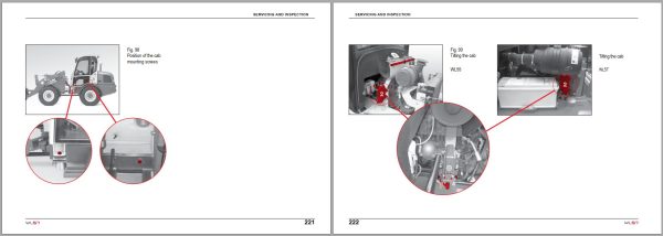
Fig. 98 Position of the cab mounting screws
Fig. 99 Tilting the cab
Fig. 100 Cab safety support
Fig. 101 Engine oil dipstick
Fig. 102 Checking the engine oil / filling the oil
Fig. 103 Engine oil drainage hose
Fig. 104 Location of the engine oil filter
Fig. 105 Position of the fuel Filters
Fig. 106 Position of the fuel filters
Fig. 107 Water separator
Fig. 108 Fuel hand-feed pump
Fig. 109 Fuel hand-feed pump
Fig. 110 Location of the air filter
Fig. 111 Air filter elements
Fig. 112 Hydraulic oil temperature sensor
Fig. 113 Engine temperature sensor
Fig. 114 V-belt
Fig. 115 Tensioning the V-belt
Fig. 116 Radiator opening
Fig. 117 Checking the antifreeze mix
Fig. 118 Cleaning the cooling system
Fig. 119 Removing and fitting the condenser of the air conditioning system
Fig. 120 Hydraulic fluid cooler
Fig. 121 Ventilation filter
Fig. 122 Hydraulic fluid dip stick
Fig. 123 Hydraulic fluid drain plugs
Fig. 124 Return filter
Fig. 125 Filter insert
Fig. 126 Differenzial
Fig. 127 PTO gear
Fig. 128 Wheel gear reduction
Fig. 129 Brake fluid container
Fig. 130 Cab vent filter
Fig. 131 Location of the windshield washer container
Fig. 132 Fusible principal
Fig. 133 Fuse boxes
Fig. 134 Fuse allocation
Fig. 135 Location of the battery
Fig. 136 Maintenance of the battery
Fig. 137 Removing the battery
Fig. 138 Connecting the jumper cables
Related Products
-
Wacker Neuson Dumper 1501 D01-05 Spare Parts Catalog 1000165936
Original price was: 20.10Current price is: 10. USDSize: 12.09 MBFormat: PDFLanguage: English, German, FrenchBrand: Wacker NeusonType of Machine: DumperType of Manual: Parts ManualModel: Wacker Neuson 1501 D01-05 DumperPart Number: 1000165936Publication Date: 2016Number of Pages: 255 Pages-50%
REALEASE :
REALEASE :
-
Wacker Neuson 4.91GB PDF DVD Collection Service Part Diagrams Assembly & Operator Manual
Original price was: 200.140Current price is: 140. USDWacker Neuson 4.91GB PDF DVD Collection Service Part Diagrams Assembly & Operator ManualSize: 4.91 GB (Unpack)Format : PDFLanguage : English, German, FranceBrand: Wacker NeusonNumber of Folder: 1,293 Files, 188 FoldersAmount of DVD: 1 DVDWindow: All Window 32 and 64 bitType of machine: Wacker Neuson Heavy Equipment– Wacker Neuson Dumper– Wacker Neuson Excavator– Wacker Neuson Skid Steer Loader– Wacker Neuson Roller– Wacker Neuson Telehandler…Type of document:– Service Manual– Operating Manual– Spare Part List (English, German, France Langues)– Diagrams– Service News– Assembly InstructionsHigh-Speed link downloadHot-30%
REALEASE :
12.18.2021
REALEASE :
12.18.2021
-
Wacker Neuson Track Excavator 803 803 Dualpower Service Manual 1000164843
20 USDSize: 9.90 MBFormat: PDFLanguage: EnglishBrand: Wacker NeusonType of Machine: Track ExcavatorType of Manual: Service Manual, Hydraulic and Electric DiagramsModel: Wacker Neuson 803, 803 Dualpower Track ExcavatorOrder Number: 1000164843Number of Pages: 196 Pages
REALEASE :
REALEASE :
-
Wacker Neuson Excavator Deere 26P Parts and Repair Service Manual
80 USDSize: 216.88 MBFormat: PDFLanguage: EnglishBrand: Wacker NeusonType of Machine: ExcavatorType of Manual: Repair Service Manual, Parts Manual, Electric and Hydraulic DiagramsModel: Wacker Neuson Deere 26P Excavator
REALEASE :
REALEASE :
-
Wacker Neuson 23.1GB PDF Part Manual, Operator Manual, Repair Manual & Wiring Diagram DVD
Original price was: 400.240Current price is: 240. USDWacker Neuson 23.1GB PDF Part Manual, Operator Manual, Repair Manual & Wiring Diagram DVDSize: 23.1 Gb (PDF Files)Language: EnglishFormat: PDFBrand: Wacker NeusonOS: All WindowsQuantity of CD: 1 DVDHigh-Speed link DownloadType of document: Part Manual, Operator Manual, Repair Manual, Electric Diagram, Hydraulic DiagramHot-40%
REALEASE :
01.11.2022
REALEASE :
01.11.2022
-
Wacker Neuson Track Excavator EZ26 Operation Service Manual
60 USDSize: 172.34 MBFormat: PDFLanguage: EnglishBrand: Wacker NeusonType of Machine: Track ExcavatorType of Manual: Service Manual, Operation Manual, Electric and Hydraulic DiagramsModel: Wacker Neuson EZ26 Track Excavator
REALEASE :
REALEASE :
-
Wacker Neuson Track Excavator EZ17 Parts and Operation Service Manual
80 USDSize: 134.58 MBFormat: PDFLanguage: EnglishBrand: Wacker NeusonType of Machine: Track ExcavatorType of Manual: Service Manual, Operation Manual, Parts Manual, Electric and Hydraulic DiagramsModel: Wacker Neuson EZ17 Track Excavator
REALEASE :
REALEASE :
-
Wacker Neuson PDF DVD Collection Service Part & Operator Manual_EN
Original price was: 150.90Current price is: 90. USDWacker Neuson PDF DVD Collection Service Part & Operator Manual_ENSize: 731 MBFormat : PDFLanguage : EnglishBrand: Wacker NeusonNumber of page: 61 FolderAmount of DVD: 1 DVDWindow: All Window 32 an d 64 bitType of machine: Wacker Neuson Heavy EquipmentType of document: Service Part & Operator ManualHot-40%
REALEASE :
14.07.2020
REALEASE :
14.07.2020