
0 ITEMSVIEW CART

-
Clark Forklift Woodward ToolKit 7.0.359.1 Program
Price range: 100 through 250 USDSize: You need to prepare 1GB of free space for the best installationInterface + Database Languages: EnglishManufacturer: ClarkRecommended OS: Windows 7, Windows 8, Windows 10, Windows 11 & x64 (Tested on Windows 10 Pro 22h2 64bit English)Hot
REALEASE :
REALEASE :
-
PSI ECONTROLS EDIS ECI 4G DISPLAY 684C 2025 Diagnostic Remote
Price range: 80 through 150 USDSize: You need to prepare 2 GB of free space for the best installationManufacturer: Power Solutions International (PSI), developed with Noregon Systems, Inc.Interface + Database Languages: EnglishSupported Operating Systems: Windows 10 (64-bit), Windows 11 (64-bit)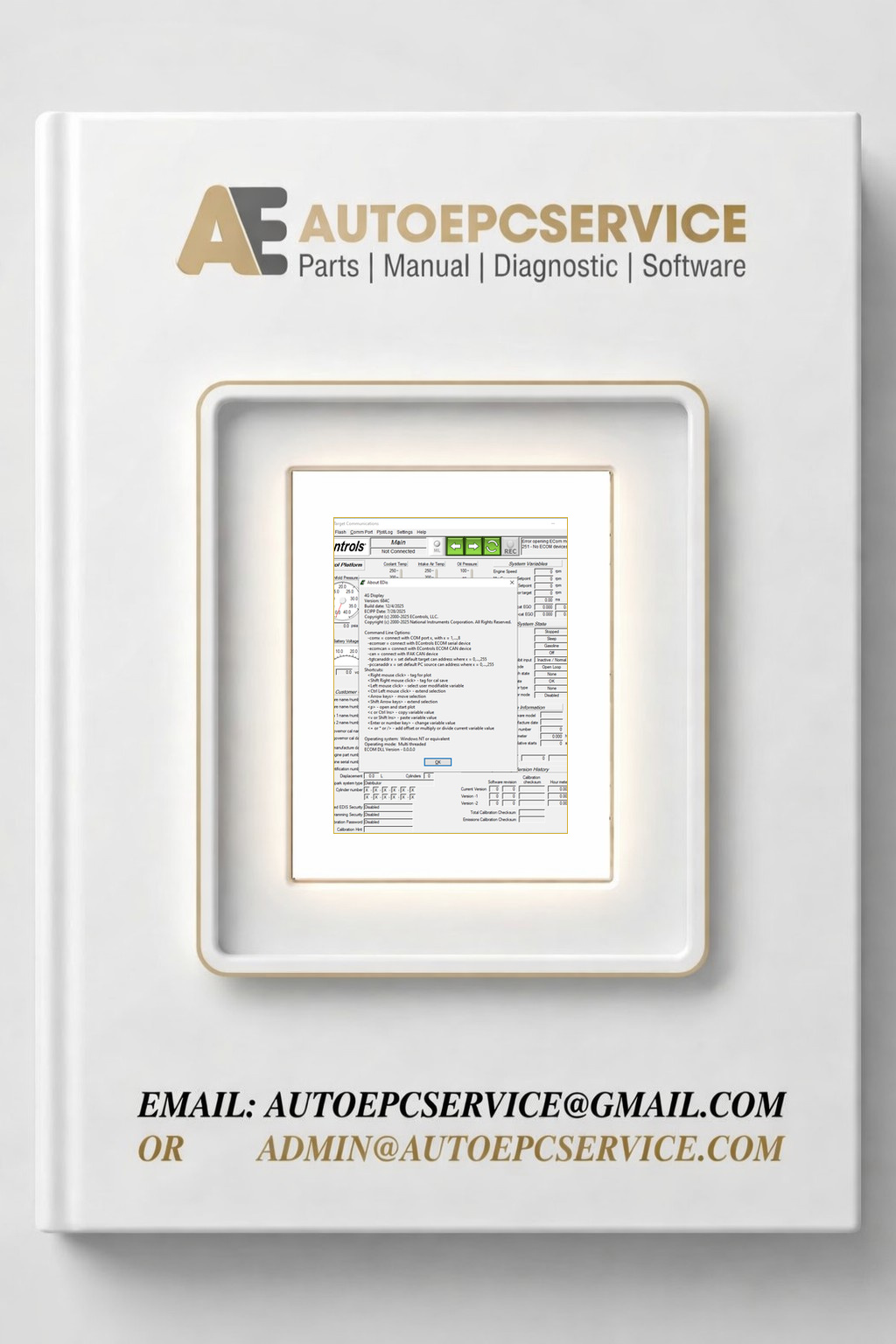
REALEASE :
REALEASE :
-
Scania SDP3 2.71 2026 Truck and Bus Diagnostic Program Remote
250 USDSize: You need to prepare 10gb of free space for installationType of Program: Diagnostic & Programmer SoftwareType of Machine: Truck and BusInterface Database Languages: English, Deutsch, Spanish, Arabic, Finnish, French, Hungarian, Italian, Japanese, Korean, Dutch, Polish, Portuguese, Russian, Swedish, Tai, Turkish, Chinese, CzechVCI Interface: KvaserRecommend OS: Tested on Windows 11 64-bit and Windows 10 64-bit (Working Well)
REALEASE :
REALEASE :
-
Scania SDP3 2.71 2026 Marine and Industrial Engine Diagnostic Program Remote
250 USDSize: You need to prepare 10 GB of free space for installationType of Program: Diagnostic & Programmer SoftwareType of Machine: Marine and IndustrialInterface Database Languages: English, Deutsch, Spanish, Arabic, Finnish, French, Hungarian, Italian, Japanese, Korean, Dutch, Polish, Portuguese, Russian, Swedish, Tai, Turkish, Chinese, CzechVCI Interface: KvaserRecommend OS: Tested on Windows 11 64-bit and Windows 10 64-bit (Working Well)
REALEASE :
REALEASE :
-
ZAPI PC Can Console 2.48 Diagnostic Program
Price range: 100 through 190 USDSize: You need to prepare 2Gb of free space for the best installationInterface Language: English, German, French, OtherOS: Windows 7, Windows 10, Windows 11 32 & 64 bit (Tested on Windows 10 Pro 22H2 64-bit)Version: 2.48
REALEASE :
REALEASE :
-
Yale One Soucre Client 07.2026 Schematic Trouble Shooting Codes
Price range: 100 through 250 USDSize: You need to prepare 10 GB of free space for installationManufacturer: YaleInterface Database Languages: Only EnglishType of Program: Diagnostic SoftwareType of vehicle: ForkliftOS: Windows 10, Window 11 64bit, (Tested on window 10 pro 22h2 64bit)
REALEASE :
REALEASE :
-
Hyster One Soucre Client 07.2026 Schematic Trouble Shooting Codes
Price range: 100 through 250 USDSize: You need to prepare 10GB of free space for installationManufacturer: HysterInterface Database Languages: Only EnglishType of Program: Diagnostic SoftwareType of vehicle: ForkliftOS: Windows 10, Window 11 64bit, (Tested on window 10 pro 22h2 64bit)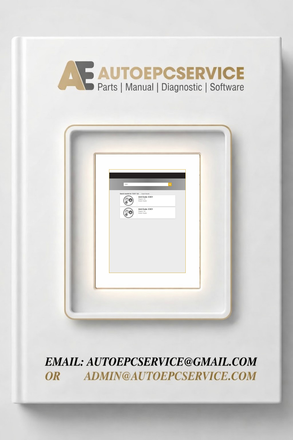
REALEASE :
REALEASE :
-
JUNGHEINRICH ForkLift ET v4.37 539 02.2025 Spare Parts Catalog
Price range: 140 through 350 USDSize: You need to prepare 50GB of free space for the best installationInterface Languages: English, Danish, German, Dutch, Norwegian, Polish, Russian (You can refer to some pictures below)Database Languages: English, Danish, German, Dutch, Norwegian, Polish, Russian (You can refer to some pictures below)Type of Programs: Spare Parts Catalogue JETI ForkLiftType of vehicle: ForkliftOS: Windows 7, Windows 8, Windows 10, Windows 11 32 & 64bit (Tested on win10 pro 22h2 64bit English)Hot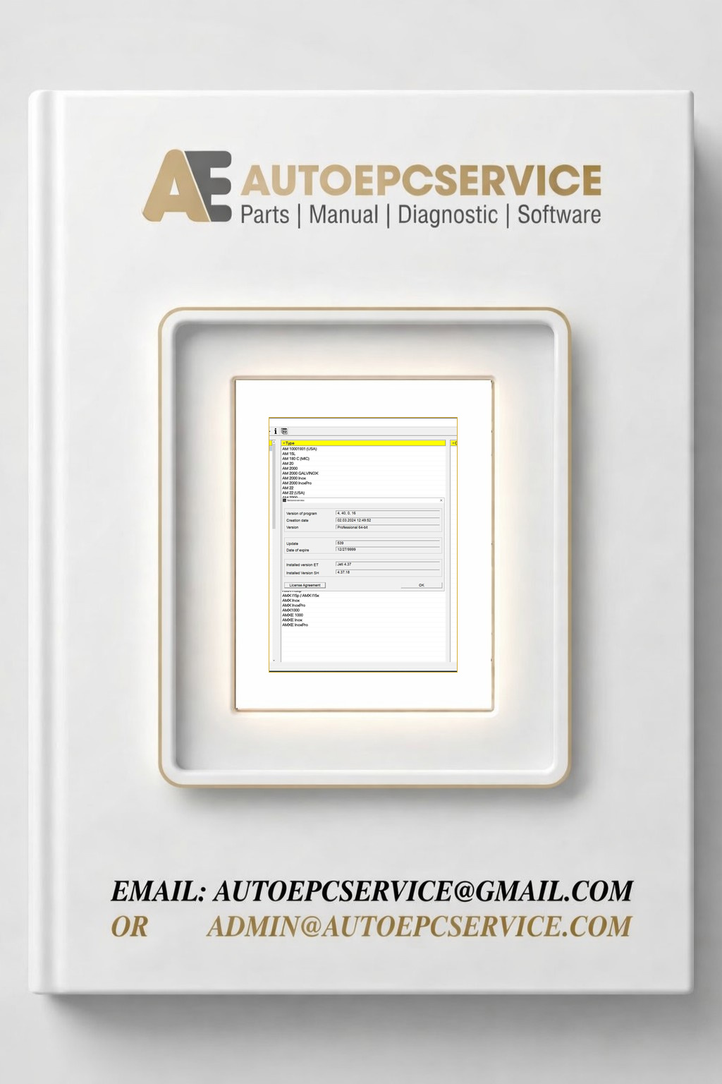
REALEASE :
REALEASE :
-
Hino Truck DXIII 1.26.3 03.2026 Diagnostic Program
Price range: 80 through 290 USDSize: You need to prepare 20GB of free space for installationType of Machine: TruckType of program: HinoInterface Languages: Japanese, Chinese, Spanish, Thai, English, Russian, French, Indonesian,Database Languages: Only EnglishRecommend OS: Windows 7, Windows 10, Windows 11 32 & 64 bit (Tested on Windows 10 Pro 22h2)
REALEASE :
REALEASE :
-
SAIC EPC 06.2026 Spare Parts Catalog Program
Price range: 60 through 100 USDSize: You need to prepare 15gb of free space for installationInterface + Database Languages: English, ChineseType of Program: EPC Spare Parts CatalogType of vehicle: CarsRecommend OS: Windows 7, Windows 10, Windows 11 x64 (Tested Windows 10 Pro 22H2)No search VIN
REALEASE :
REALEASE :
-
YANMAR SMART ASSIST Only Industrial Engine V2.54 06.2026 Diagnostic Program
Price range: 90 through 350 USDSize: You need to prepare 5GB of free space for installationType of Program: Diagnostic Tool Offline VersionInterface Language: English, Chinese, Japanese, KoreanDatabase Language: Only EnglishType of machine: Industrial EngineOS: Windows 7, Windows 8, Windows 10, and Windows 11 (Tested on Windows 10 64-bit English)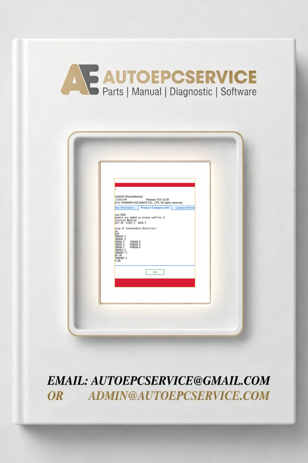
REALEASE :
REALEASE :
-
VMware Mercury EPC Marine EU NA 06.2026 Q2.2026 Spare Parts Catalog
200 USDVMware Included:1/ Mercury Marine Europe EPC Q2 06.2026 Spare Parts Catalog VMWARE2/ Mercury Marine North America EPC Q2 06.2026 Spare Parts Catalog VMWARESize: You need to prepare 100GB fof ree space for installationInterface + Database Languages: English, Hungarian, Dutch, Danish, Spanish, Italian, German, Polish, Turkish, French, Czech, SwedishType of Program: Spare parts catalogVMware OS: Windows 7 32bit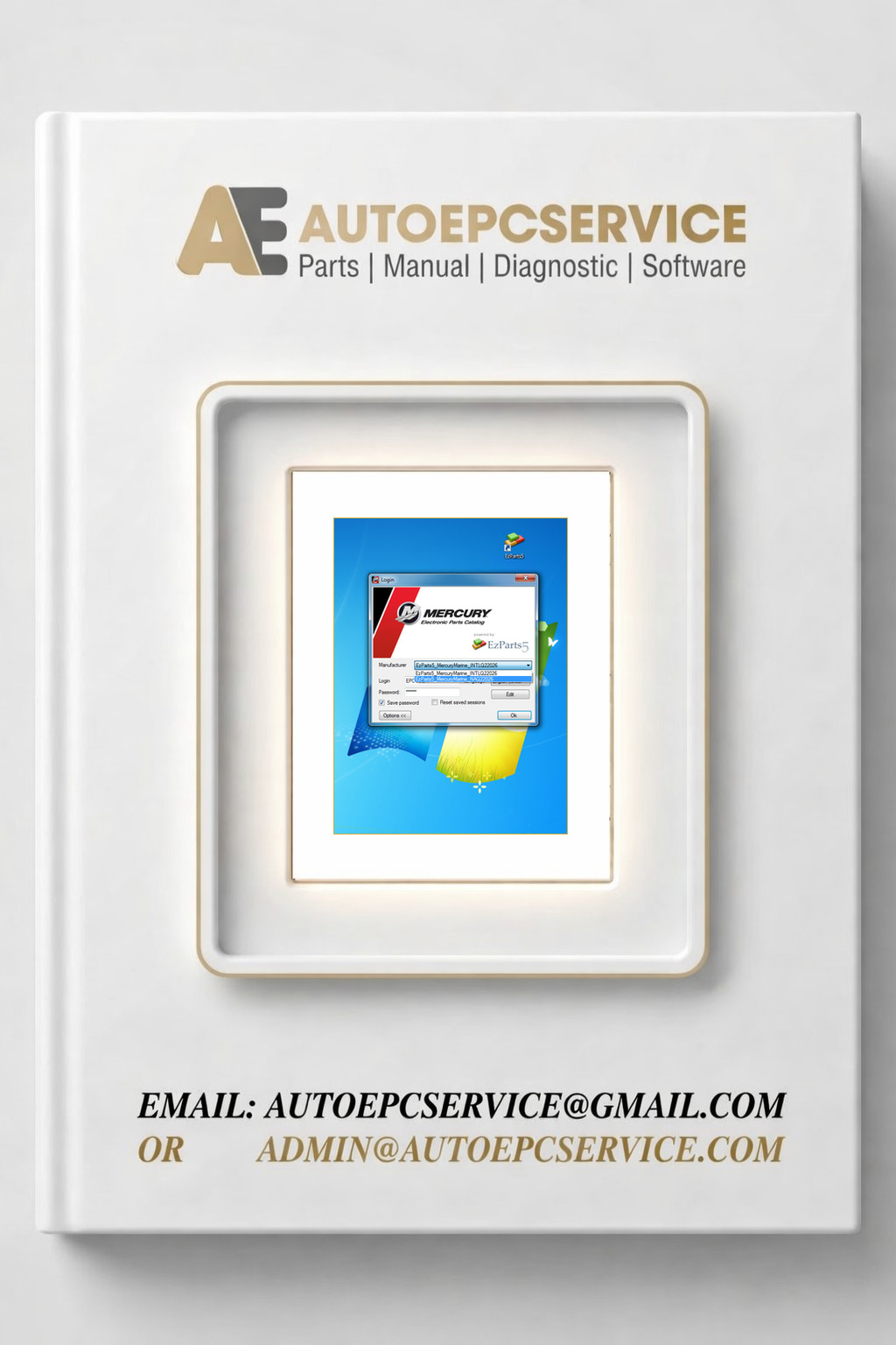
REALEASE :
REALEASE :
-
Toyota GTS 02.2026 Diagnostic Program Remote
120 USDSize: You need to prepare 10GB of free space for the best installationManufacturer: Toyota Motor CorporationType of Program: Diagnostic ProgramRecommend: Windows 10 , Windows 11 64bit (Tested on window 10 pro 22h2 64bit)NOTE: PRICE FOR 1 YEAR LICENSE OFFLINE AND ONE PC
REALEASE :
REALEASE :
-
YANMAR SMART ASSIST Only Industrial Engine V2.54 06.2026 Diagnostic Program
Price range: 90 through 350 USDSize: You need to prepare 5GB of free space for installationType of Program: Diagnostic Tool Offline VersionInterface Language: English, Chinese, Japanese, KoreanDatabase Language: Only EnglishType of machine: Industrial EngineOS: Windows 7, Windows 8, Windows 10, and Windows 11 (Tested on Windows 10 64-bit English)REALEASE :
REALEASE :
-
Manitou EST 2025B Diagnostic Program Remote
350 USDSize: You need to prepare 20GB of free space for the best installationRecommended OS: Windows 10, Windows 11 32 & 64-bit (Tested on Windows 10 Pro 22H2 64-bit English)Interface + Database Language: EnglishHot
REALEASE :
REALEASE :
-
JPRO Commercial Vehicle 2026 v1.1 Diagnostic Program Remote
100 USDSize: You need to prepare 10 GB of free space on disk C for installationRecommend OS: Windows 10, 11 32 64 bit (Tested on Windows 10, 11 Pro 64 bit)How To Install by Remote1. Download Setup.2. Remote install the software via TeamViewer, AnyDesk3. If need do install + active full contact us
REALEASE :
REALEASE :
-
CAT ET Perkins EST 2026a Diagnostic Program Remote Combo
170 USDThe combo included:Size: You need to prepare 5GB of free space for installationRecommend OS: Windows 10, Windows 11 32 & 64bit (Tested on Windows 10 Pro 22H2 64bit english)Hot
REALEASE :
REALEASE :
-
PERKINS EST 2026a Diagnostic Program Remote
120 USDSize: You need to prepare 5GB of free space for installationRecommend OS: Windows 7, Windows 8, Windows 10, Windows 11 32 & 64bit (Tested on Windows 10 Pro 22H2 64bit)HotREALEASE :
REALEASE :
-
Hyundai Doosan DL0608 T4F DPF v0130 04.2026 Diagnostic Program Remote
120 USDSize: You need to prepare 1GB of free space for the best installation Manufacturer: Doosan Bobcat Hyundai Database Language: English Interface Language: English, Korean OS: Windows 10 or Windows 11 Pro x64 (Tested on window 10 pro 22h2 64bit english) Level: – Developer – Supervisor – Service
REALEASE :
REALEASE :
-
Doosan G2 Scan ECU 02.20 04.2026 Diagnostic Program Remote
120 USDSize: You need to prepare 1GB of free space for the best installation Manufacturer: Bobcat Database Language: English Interface Language: English, Korean OS: Windows 10 or Windows 11 Pro x64 (Tested on window 10 pro 22h2 64bit english) Level: – Developer – Supervisor – Service
REALEASE :
REALEASE :
-
Doosan G2 Scan DCU 03.20 04.2026 Diagnostic Program Remote
120 USDSize: You need to prepare 1GB of free space for the best installation Manufacturer: Bobcat Database Language: English Interface Language: English, Korean OS: Windows 10 or Windows 11 Pro x64 (Tested on window 10 pro 22h2 64bit english) Level: – Developer – Supervisor – Service
REALEASE :
REALEASE :
-
Bobcat Engine Analyzer 02.20 ECU 04.2026 Diagnostic Program Remote
150 USDSize: You need to prepare 1GB of free space for the best installationManufacturer: BobcatDatabase Language: EnglishInterface Language: English, KoreanOS: Windows 10 or Windows 11 Pro x64 (Tested on window 10 pro 22h2 64bit english)Level:– Developer– Supervisor– Service
REALEASE :
REALEASE :
-
Bobcat Engine Analyzer 03.20 DCU 04.2026 Diagnostic Program Remote
150 USDSize: You need to prepare 1GB of free space for the best installationBrand: BobcatDatabase Language: EnglishInterface Language: English, KoreanOS: Windows 10 or Windows 11 Pro x64Level:– Developer– Supervisor– Service
REALEASE :
REALEASE :
-
PALDIAG.NET 2020 Diagnostic Program Remote
180 USDSize: You need to prepare 20 GB of free space on disk C for the best installationType of program: Diagnostic Software for PALFINGER ProductsType of vehicle: Heavy EquipmentInterface Languages: English, Italian, Russian, Polish, Spanish, French, Portuguese, German, Dutch, Danish.Database Language: EnglishOS: Windows 10 Pro 22H2 is the best (Tested)Hot
REALEASE :
REALEASE :
-
Manitou Articulated Loader AL ALT Series Service Operator Part Manual Update 2024
200 USDSite: 1.83 GBFormat: PDFLanguage: EnglishBrand: ManitouType of Machine : Articulated LoaderType of Document: Service Manual,Repair Manual, Operator Manuals, Part ManualModels: AL Series, ALT SeriesUpdate: 2024Hot
REALEASE :
REALEASE :
-
Manitou Skid-Steer Loader R RT Series Service Operator Part Manual Update 2024
250 USDSite: 3.73 GBFormat: PDFLanguage: EnglishBrand: ManitouaType of Machine : Skid-Steer LoaderType of Document: Service Manual,Repair Manual, Operator Manuals, Part ManualModels: R Series, RT SeriesUpdate: 2024Hot
REALEASE :
REALEASE :
-
Manitou Telehandler MB MBL MBL-X Series Service Operator Part Manual Update 2024
200 USDSite: 2.58 GBFormat: PDFLanguage: EnglishBrand: ManitouType of Machine : TelehandlerType of Document: Service Manual,Repair Manual, Operator Manuals, Part ManualModels: MB Series, MBL Series, MBL-X SeriesUpdate: 2024Hot
REALEASE :
REALEASE :
-
Manitou TJ TJP TJ-X TJ-XP Series Service Operator Part Manual Update 2024
200 USDSite: 1.57 GBFormat: PDFLanguage: EnglishBrand: ManitouType of Machine : Mobile Elevating Work PlatformsType of Document: Service Manual,Repair Manual, Operator Manuals, Part ManualModels: TJ Series, TJP Series, TJ-X Series, TJ-XP SeriesUpdate: 2024Hot
REALEASE :
REALEASE :
-
Manitou Telehandler MTA Series Service Operator Part Manual Update 2024
200 USDSite: 2.11 GBFormat: PDFLanguage: EnglishBrand: ManitouType of Machine : TelehandlerType of Document: Service Manual,Repair Manual, Operator Manuals, Part ManualModels: MTA SeriesUpdate: 2024Hot
REALEASE :
REALEASE :
-
Manitou Telehandler MVT Series Service Operator Part Manual Update 2024
250 USDSite: 2.47 GBFormat: PDFLanguage: English, some French, some Italian, some Deutsch, some SpanishBrand: ManitouType of Machine : TelehandlerType of Document: Service Manual,Repair Manual, Operator Manuals, Part ManualModels: MVT SeriesUpdate: 2024Hot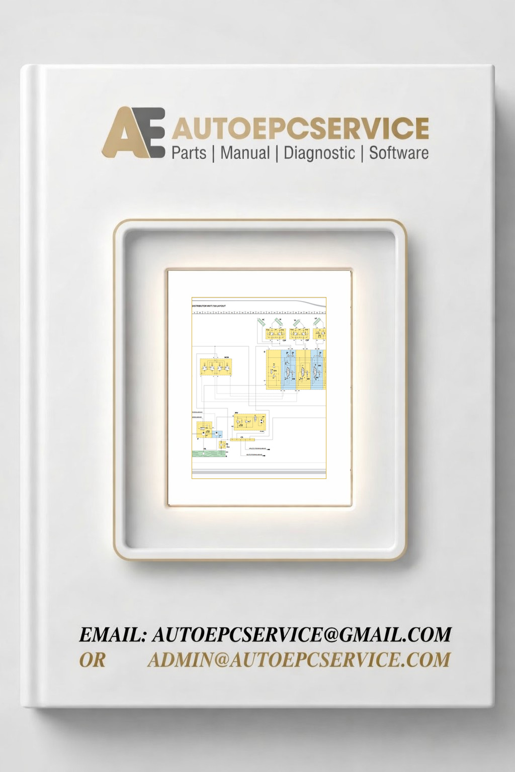
REALEASE :
REALEASE :
-
Manitou Telescopic Handlers MXT Series Service Operator Part Manual Update 2024
250 USDSite: 6.66 GBFormat: PDFLanguage: English, some FrenchBrand: ManitouType of Machine : Telescopic HandlersType of Document: Service Manual,Repair Manual, Operator Manuals, Part ManualModels: MXT SeriesUpdate: 2024Hot
REALEASE :
REALEASE :
-
Manitou Telehandler MT MT-X Series Service Operator Part Manual Update 2024
800 USDSite: 34.2 GBFormat: PDFLanguage: English, some FrenchBrand: ManitouType of Machine : TelehandlerType of Document: Service Manual,Repair Manual, Operator Manuals, Part ManualModels: MT Series, MT-X SeriesUpdate: 2024Hot
REALEASE :
REALEASE :
-
Manitou Forklift TMT TMT-X Series Service Operator Part Manual Update 2024
200 USDSite: 4.90 GBFormat: PDFLanguage: English, some FrenchBrand: ManitouType of Machine : ForkliftType of Document: Service Manual,Repair Manual, Operator Manuals, Part ManualModels: TMT Series, TMT-X SeriesUpdate: 2024Hot
REALEASE :
REALEASE :
-
Manitou Telehandler MRT MRT-X Series Service Operator Part Manual Update 2024
800 USDSite: 26.7 GBFormat: PDFLanguage: English, some FrenchBrand: ManitouType of Machine : TelehandlerType of Document: Service Manual,Repair Manual, Operator Manuals, Part ManualModels: MRT Series, MRT-X SeriesUpdate: 2024Hot
REALEASE :
REALEASE :
-
Changan Automotive 3.09 GB PDF Service Manual Wiring Diagram
100 USDSize: 3.09 GBFormat: PDFLanguage: EnglishBrand: Chana, ChanganType of Machine: AutomotiveType of Manual: Service Manual, Wiring Diagram, Workshop Manual, Electric DiagramHot
REALEASE :
REALEASE :
-
Lifan Car 1.8 GB PDF User Service Manual Parts Catalog
150 USDSize: 1.82 GBFormat: PDF, XLSLanguage: English, ChineseBrand: LifanType of Machine: AutomotiveType of Manual: Wiring Diagram, Service Manual, Owner’s Manual, User Manual, Parts CatalogHot
REALEASE :
REALEASE :