
0 ITEMSVIEW CART

✓
Expert Support
✓
Full Speed
✓
100% Working
Skyjack Rough Terrain Scissors SJ9250RT Service Manual 167323AGA 2023
Size: 22.33 MB
Format: PDF
Language: English
Brand: Skyjack
Type of Machine: Rough Terrain Scissors
Type of Manual: Service Manual, Electrical Schematic, Hydraulic Schematic
Model: Skyjack SJ9250RT Rough Terrain Scissors
Serial Number: 50001153 – 50999999
Part Number: 167323AGA
Publication Date: 2023
Number of Pages: 180 Pages
20 USD
- Description
Description
Contents:
Section 1 – Scheduled Maintenance
1.1 Read and Heed
1.2 Maintenance and Inspection Schedule
1.3 Hydraulic System & Component Maintenance and Repair
1.4 Railing Maintenance and Repair
1.5 About this Section
1.6 Owner’s Annual Inspection Record
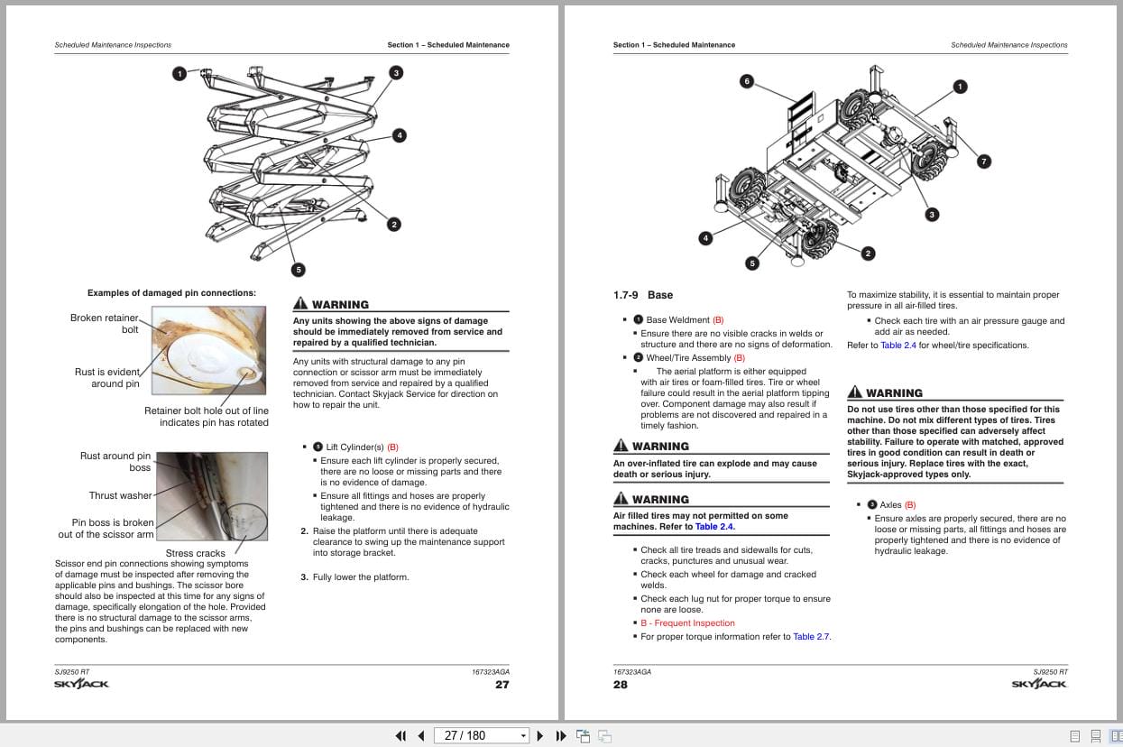
1.7 Scheduled Maintenance Inspections
1.8 Function Tests
Section 2 – Maintenance Tables and Diagrams
2.1 Specifications and Features 50 001 320 – 50 999 999 (Including 50 001 302 – 50 001 307)
2.2 Specifications and Features 50 001 153 – 50 001 320
2.3 Maximum Platform Capacities (Evenly Distributed)
2.4 Tire Specifications
2.5 Floor Loading Pressure
2.6 Fluids
2.7 Torque Specifications
2.8 Torque Specifications for Fasteners (Imperial)
2.9 Torque Specifications for Fasteners (Metric)
2.10 Torque Specifications for Hydraulic Couplings and Hoses
Section 3 – System Component Identification and Schematics
3.1 Electrical Symbol Chart
3.2 Hydraulic Symbol Chart
3.3 AC Cord Color Code
3.4 Hydraulic Component Parts List
3.5 Electrical Component Parts List
3.6 Platform Control Console Wiring – All Options (ANSI/CSA)
3.7 Control Cable Assemblies Diagram
3.8 Outrigger and Hydraulic Generator Control Console Wiring
3.9 Base Control Console Wiring (ANSI/CSA)
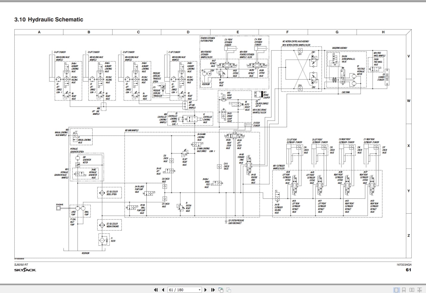
3.10 Hydraulic Schematic
3.11 HydraulicManifold Components and Port Identification
3.12 Main Manifold Wiring Diagram
3.13 Emergency Lowering System Wiring Diagram (ANSI/CSA)
3.14 Electrical Wiring Diagram – Powered Extension Platform
3.15 Electrical Panel Diagram – Oil Cooler Option (ANSI/CSA)
3.16 Electrical Panel Diagram – Dual Fuel Engine with Hydraulic Generator Option (ANSI/CSA)
3.17 Electrical Panel Diagram – Diesel Engine with Hydraulic Generator Option (ANSI/CSA)
3.18 Auto-Leveling Outrigger Wiring Diagram
3.19 Horn, Light, and Beeper Wiring Diagram
3.20 Engine Harness Wiring Diagram – Kubota Diesel Engine
3.21 Engine Interface Harness Wiring Diagram – Kubota Dual Fuel Engine
3.22 Telematics Harness Wiring Diagram – Kubota Diesel Engine
3.23 Telematics Harness Wiring Diagram – Kubota Duel Fuel Engine
3.24 Flashing Light Relay Harness
3.25 Electrical Panel Diagram – S/N 50 002 025. 50 002 025, 50 002 029 – 50 999 999
3.26 Electrical Panel Diagram – S/N 50 002 028, 50 002 027, 50 001 153 – 50 002 024
3.27 Electric Panel with Positive Air Shutoff Option – S/N 50 002 025, 50 002 026, 50 002 029 – 50 999 999
3.28 Electric Panel with Positive Air Shutoff Option – S/N 50 002 028, 50 002 027, 50 001 153 – 50 002 024
3.29 Positive Air Shutoff Harness Wiring Diagram – Diesel Engine
3.30 Electrical Schematic Diagram – Kubota Diesel Engine with All Option (ANSI/CSA) – S/N 50 002 025, 50 002 026, 50 002 029 – 50 999 999
3.31 Electrical Schematic Diagram – Kubota Diesel Engine with All Option (ANSI/CSA) – S/N 50 002 028, 50 002 027, 50 001 153 – 50 002 024
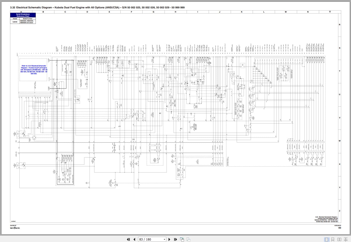
3.32 Electrical Schematic Diagram – Kubota Dual Fuel Engine with All Options (ANSI/CSA) – S/N 50 002 025, 50 002 026, 50 002 029 – 50 999 999
3.33 Electrical Schematic Diagram – Kubota Dual Fuel Engine with All Options (ANSI/CSA) – S/N 50 002 028, 50 002 027, 50 001 1533 – 50 002 024
3.34 Electrical Schematic Diagram – Kubota Dual Fuel Engine with No Options (ANSI/CSA) – S/N 50 002 025, 50 002 026, 50 002 029 – 50 999 999
3.35 Electrical Schematic Diagram – Kubota Dual Fuel Engine with No Options (ANSI/CSA) – S/N 50 002 028, 50 002 027, 50 001 153 – 50 002 024
3.36 Electrical Schematic Diagram – All Options (KC) – S/N 50 002 025, 50 002 026, 50 002 029 – 50 999 999
3.37 Electrical Schematic Diagram – All Options (KC) – S/N 50 002 028, 50 002 027, 50 001 153 – 50 002 024
3.38 Engine Electrical Schematic – Kubota Dual Fuel Engine
3.39 Engine Interface Harnesses – Kubota Dual Fuel Engine
3.40 ECU Wiring Diagram – Kubota Dual Fuel Engine
3.41 Platform Control Box Wiring
Section 4 – Troubleshooting Information
4.1 Introduction
4.2 Electrical System
4.3 Hydraulic System
Section 5 – Procedures
5.1 General
5.2 Platform
5.3 Scissors
5.4 Engine
5.5 Base
5.6 Hydraulic
5.7 Outriggers
5.8 EZcal Diagnostic Tool
5.9 OCM1 Control Module
5.10 GP-106 Control Module
5.11 GP-108 Control Module
Related Products
-
Skyjack Vertical Mast Lifts SJ12E SJ16E SJ20E Parts Manual 241913ADA 2023
15 USDSize: 7.44 MBFormat: PDFLanguage: EnglishBrand: SkyjackType of Machine: Vertical Mast LiftsType of Manual: Parts ManualModel: Skyjack SJ12E, SJ16E, SJ20E Vertical Mast LiftsSerial Number: A601000906 – A601999999Part Number: 241913ADAPublication Date: 2023Number of Pages: 138 Pages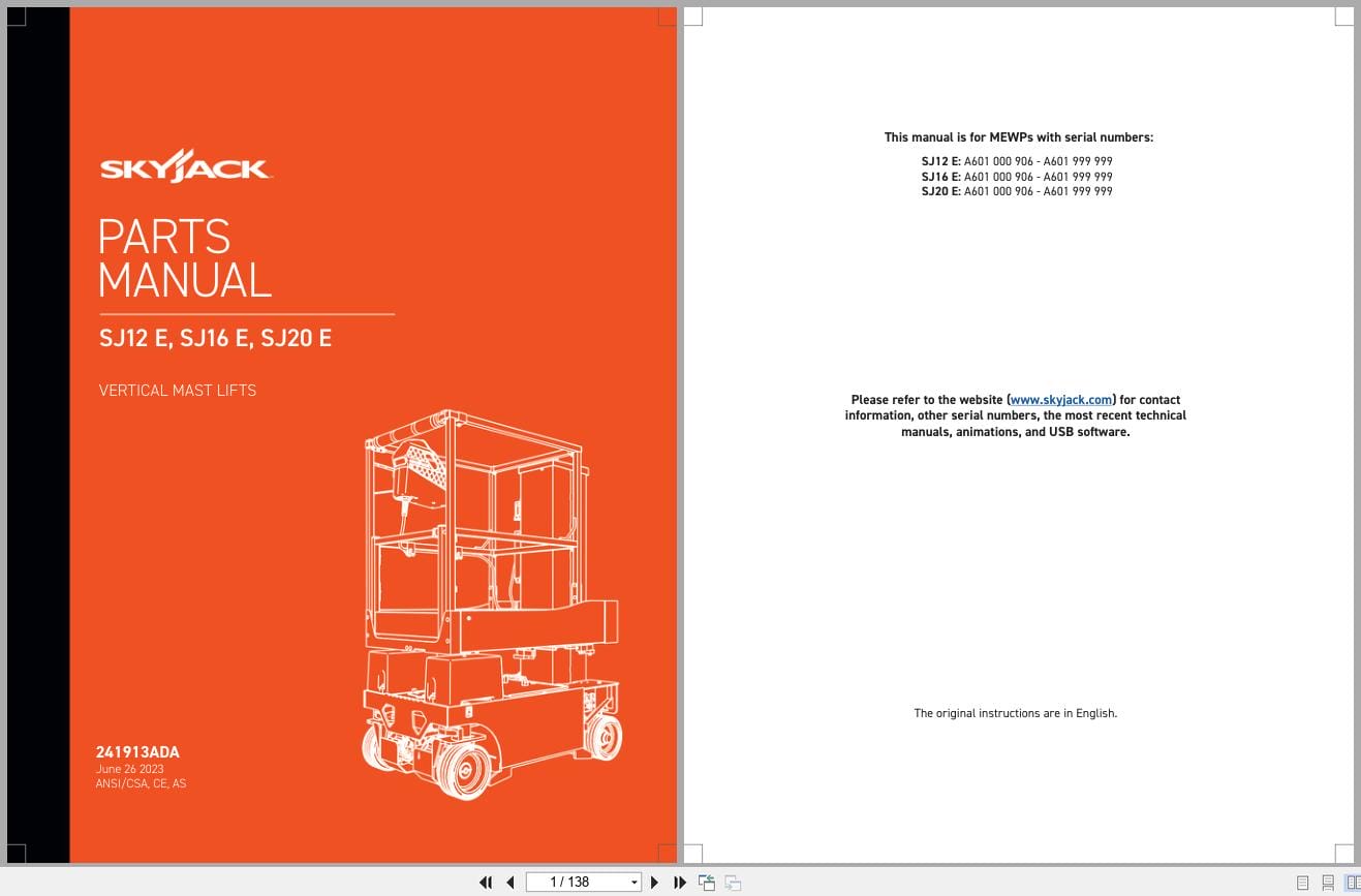
REALEASE :
REALEASE :
-
Skyjack Vertical Mast Lifts SJ12E SJ16E SJ20E Operating Manual 243762ABA 2022
10 USDSize: 5.67 MBFormat: PDFLanguage: EnglishBrand: SkyjackType of Machine: Vertical Mast LiftsType of Manual: Operating ManualModel: Skyjack SJ12E, SJ16E, SJ20E Vertical Mast LiftsSerial Number: A601001639 & abovePart Number: 243762ABAPublication Date: 2022Number of Pages: 92 Pages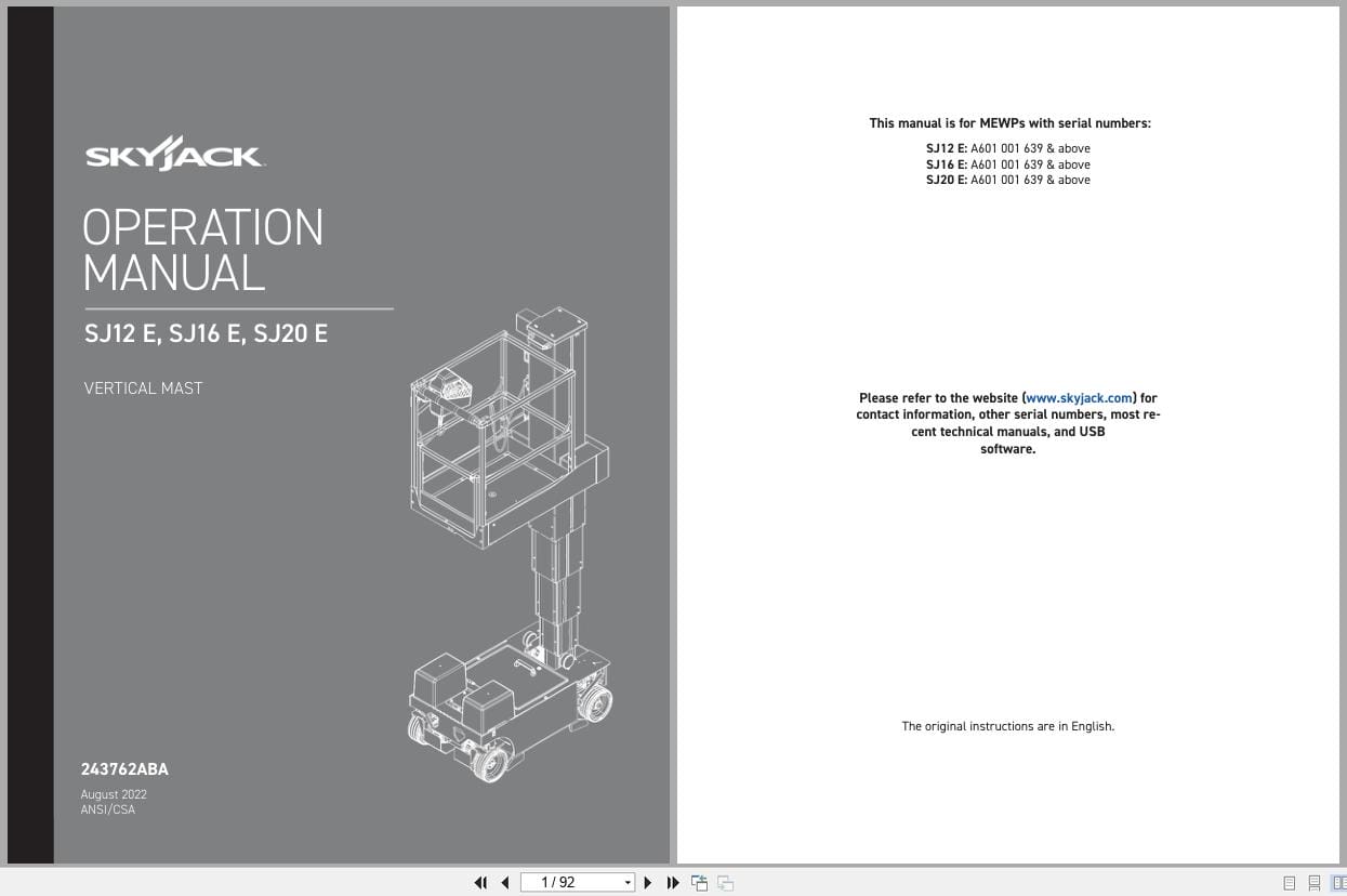
REALEASE :
REALEASE :
-
Skyjack Lift Aerial Working Platform AWP All Models 2020 Documentation PDF DVD
Original price was: 200.110Current price is: 110. USDSkyjack Lift Aerial Working Platform AWP All Models 2020 Documentation PDF DVDSize: 6.39 GBFormat: PDFLanguage: EnglishBrand: Skyjack LiftAmount of DVD: 1 DVDWindow: All Window 32 & 64 bit, Mac OSType of Vehicle: Aerial working platform (AWP)Type of Document: Operating – Parts – Service Manuals PDFHot-45%
REALEASE :
30.05.2020
REALEASE :
30.05.2020
-
Skyjack Vertical Mast Lifts SJ20 Operating Manual 236504AFA 2022
10 USDSize: 5.17 MBFormat: PDFLanguage: EnglishBrand: SkyjackType of Machine: Vertical Mast LiftsType of Manual: Operating ManualModel: Skyjack SJ20 Vertical Mast LiftsSerial Number: A601000001 – A601000905Part Number: 236504AFAPublication Date: 2022Number of Pages: 94 Pages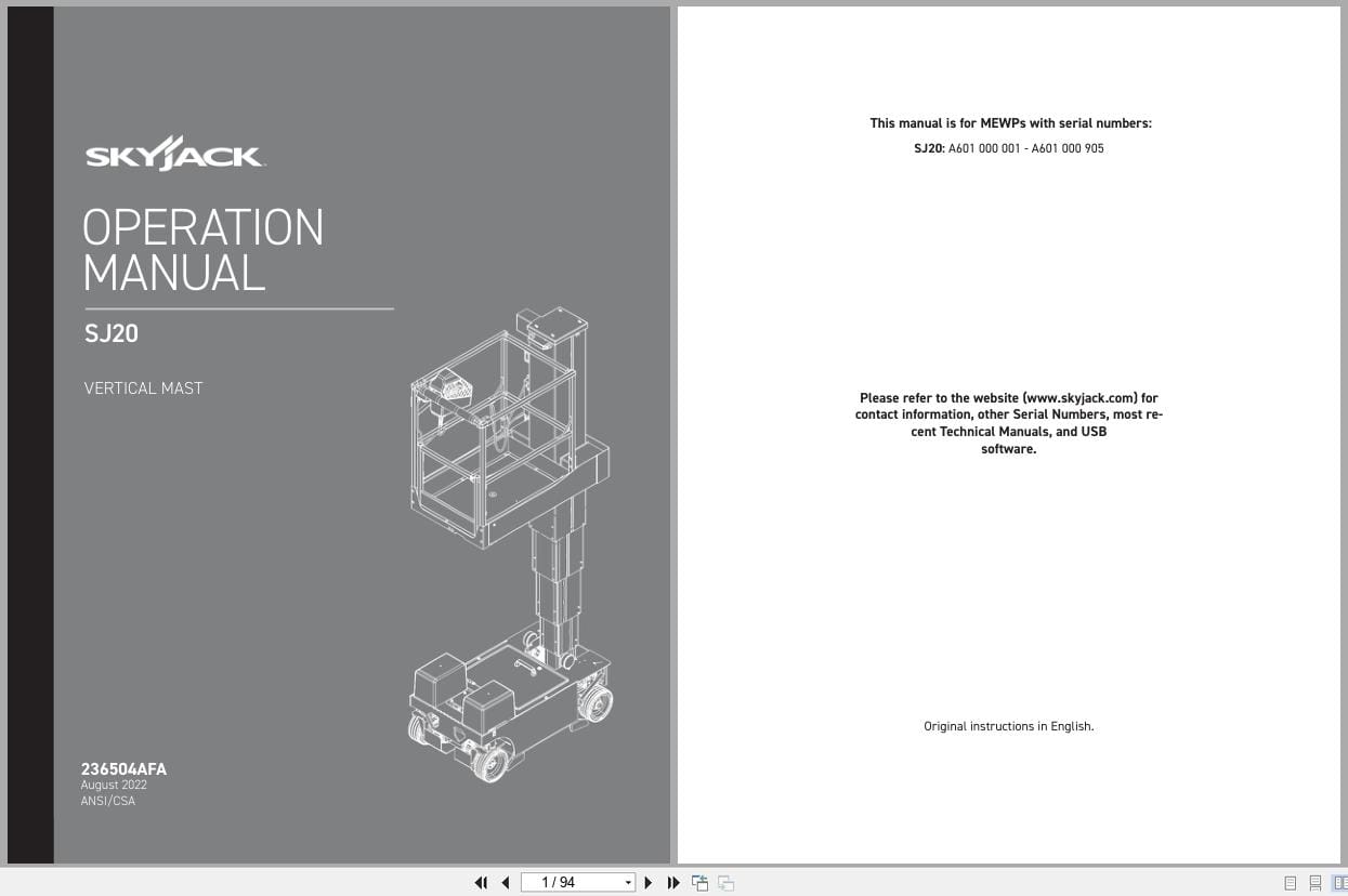
REALEASE :
REALEASE :
-
Skyjack NA 4.93GB PDF Operating Parts Service Manuals
Original price was: 200.140Current price is: 140. USDThis is a service information package, you will need to use this to repair a vehicleHot-30%
REALEASE :
REALEASE :
-
Skyjack Vertical Mast Lifts SJ20 Service Manual 238886ADA 2023
20 USDSize: 9.74 MBFormat: PDFLanguage: EnglishBrand: SkyjackType of Machine: Vertical Mast LiftsType of Manual: Service Manual, Electrical SchematicModel: Skyjack SJ20 Vertical Mast LiftsSerial Number: A601000001 to A601000905Part Number: 238886ADAPublication Date: 2023Number of Pages: 158 Pages
REALEASE :
REALEASE :
-
Skyjack Vertical Mast Lifts SJ12E SJ16E SJ20E Service Manual 241914ADA 2023
20 USDSize: 10.70 MBFormat: PDFLanguage: EnglishBrand: SkyjackType of Machine: Vertical Mast LiftsType of Manual: Service Manual, Electrical SchematicModel: Skyjack SJ12E, SJ16E, SJ20E Vertical Mast LiftsSerial Number: A601000906 – A601999999Part Number: 241914ADAPublication Date: 2023Number of Pages: 154 Pages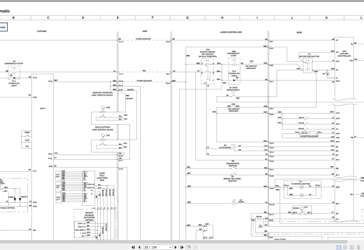
REALEASE :
REALEASE :
-
Skyjack Vertical Mast Lifts SJ20 Parts Manual 238885ACA 2023
15 USDSize: 6.43 MBFormat: PDFLanguage: EnglishBrand: SkyjackType of Machine: Vertical Mast LiftsType of Manual: Parts ManualModel: Skyjack SJ20 Vertical Mast LiftsSerial Number: A601000001 to A601000905Part Number: 238885ACAPublication Date: 2023Number of Pages: 116 Pages
REALEASE :
REALEASE :