")
Expert Support
Full Speed
100% Working
Skyjack Telescopic Booms SJ40T SJ45T Service Manual 207563AL 2023
20 USD
- Description
Description
Contents:
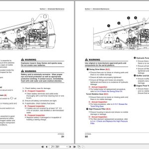
Section 1 – Scheduled Maintenance
1.1 Read and Heed
1.2 Maintenance and Service
1.3 Scheduled Maintenance
1.4 Owner’s Annual Inspection Record
1.5 Pre-Delivery/Maintenance Inspection Checklist
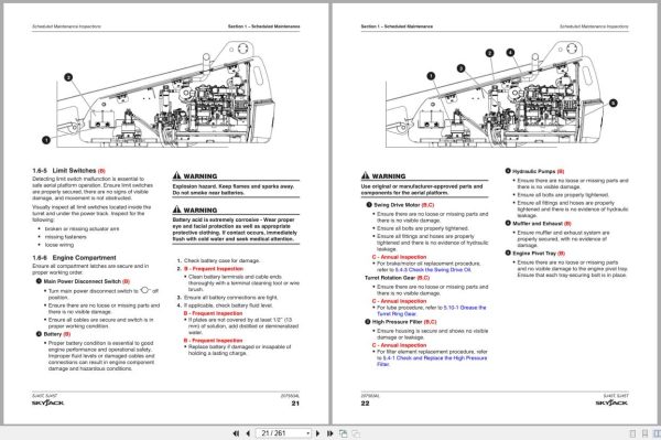
1.6 Scheduled Maintenance Inspections
1.7 Function Tests
Section 2 – Maintenance Tables and Diagrams
2.1 Standard Hose Numbering System
2.2 Aerial Platform Torque Specifications
2.3 Axle Torque Specifications
2.4 Torque Specifications for Fasteners (US)
2.5 Torque Specifications for Fasteners (Metric)
2.6 Torque Specifications for Hydraulic Couplings & Hoses
2.7 Axles Maintenance Intervals
2.8 Tire Specifications
2.9 Floor Loading Pressure
2.10 Hydraulic Specifications & Gear Oil
2.11 Specifications and Features – Dimensional Data
2.12 Specifications and Features – Performance and Speeds
2.13 Engine Specifications
2.14 Dimension and Reach Diagram – SJ40T
2.15 Dimension and Reach Diagram – SJ45T
2.16 Axle Oscillation Diagrams
Section 3 – System Component Identification and Schematics
3.1 Electrical Symbol Chart
3.2 Hydraulic Symbol Chart
3.3 Wire Number and Color Code
3.4 Hydraulic Parts List
3.5 Electrical Component Parts List
3.6 Rotary Manifold Port Identification
3.7 Brake Manifold Port Identification
3.8 System Pump Port Identification
3.9 Drive Pump Port Identification
3.10 Drive Motor Port Identification
3.11 Jib Valve Port Identification – SJ45T
3.12 No Jib Valve Port Identifications – SJ40T
3.13 Main Manifold Port Identification
3.14 Main Manifold Electrical Component Identification
3.15 Main Manifold Hydraulic Component Identification
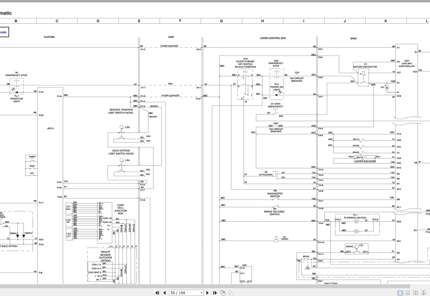
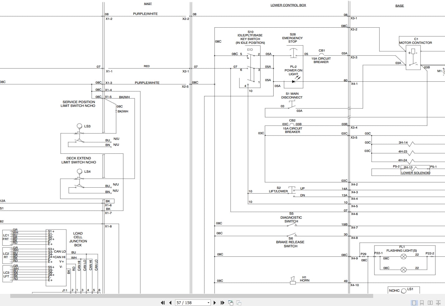
3.16 Main Harness Wiring Diagram
3.17 ECU Engine Wiring Diagram – Deutz D2011
3.18 Engine Interface Harness – Deutz D2.9L
3.19 Engine Interface Harness – Kubota WG2503
3.20 Glow Plug Harness – Deutz D2.9L
3.21 Glow Plug Harness – Deutz D2011
3.22 Platform Harnesses
3.23 Platform Control Cables
3.24 Limit Switch Connections
3.25 Load Sensing Cable Connection (CE & AS)
3.26 Flashing Light Connection
3.27 Oil Cooler Harness Connections
3.28 Generator Wire Kit Connections
3.29 Load Circuit Wiring
3.30 SGE Schematic
3.31 SGE Platform Control Box Wiring Diagram
3.32 Differential Lock Harness
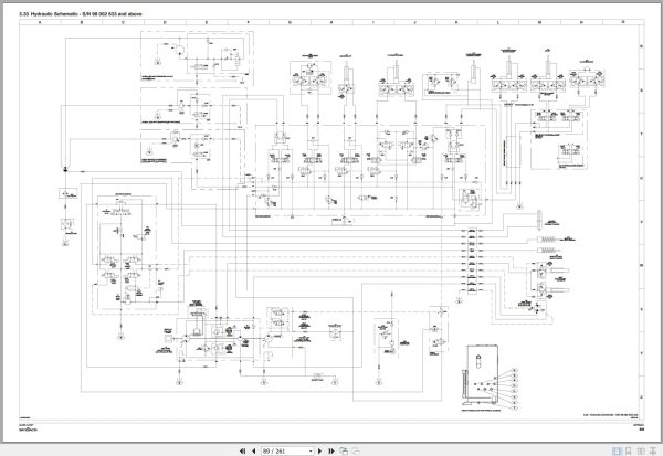
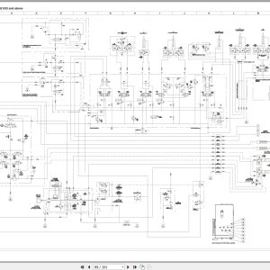
3.33 Hydraulic Schematic – S/N 98 002 633 and above
3.34 Hydraulic Schematic – S/N 98 002 632 and below
3.35 Platform Controls Wiring – SJ40T ANSI/CSA Kubota
3.36 Platform Controls Wiring – SJ40T ANSI/CSA Deutz & Perkins
3.37 Platform Controls Wiring – SJ45T ANSI/CSA Kubota
3.38 Platform Controls Wiring – SJ45T ANSI/CSA Deutz & Perkins
3.39 Platform Controls Wiring – SJ45T CE Deutz
3.40 Platform Controls Wiring – SJ45T AS Deutz
3.41 Base Controls Wiring – SJ40T ANSI/CSA Kubota
3.42 Base Controls Wiring – SJ40T ANSI/CSA Deutz D2011
3.43 Base Controls Wiring – SJ40T ANSI/CSA Deutz D2011 with Positive Air Shut-Off Option
3.44 Base Controls Wiring – SJ40T ANSI/CSA Deutz D2.9L
3.45 Base Controls Wiring – SJ40T ANSI/CSA Deutz D2.9L with Positive Air Shut-Off Option
3.46 Base Controls Wiring – SJ40T ANSI/CSA Perkins
3.47 Base Controls Wiring – SJ45T ANSI/CSA Kubota
3.48 Base Controls Wiring – SJ45T ANSI/CSA Deutz D2011
3.49 Base Controls Wiring – SJ45T ANSI/CSA Deutz D2011 with Positive Air Shut-Off Option
3.50 Base Controls Wiring – SJ45T ANSI/CSA Deutz D2.9L
3.51 Base Controls Wiring – SJ45T ANSI/CSA Deutz D2.9L with Positive Air Shut-Off Option
3.52 Base Controls Wiring – SJ45T ANSI/CSA Perkins
3.53 Base Controls Wiring – SJ45T CE Deutz D2.2
3.54 Base Controls Wiring – SJ45T CE Deutz D2011
3.55 Base Controls Wiring – SJ45T AS Deutz D2011
3.56 Electrical Schematic – ANSI/CSA Kubota (S/N 98003579 and below)
3.57 Electrical Schematic – ANSI/CSA Kubota (S/N 98003580 and above)
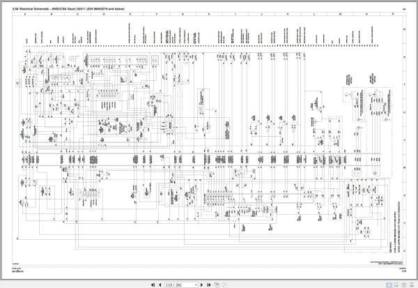
3.58 Electrical Schematic – ANSI/CSA Deutz D2011 (S/N 98003579 and below)
3.59 Electrical Schematic – ANSI/CSA Deutz D2011 (S/N 98003580 and above)
3.60 Electrical Schematic – ANSI/CSA Deutz D2.9L (S/N 98003579 and below)
3.61 Electrical Schematic – ANSI/CSA Deutz D2.9L (S/N 98003580 and above)
3.62 Electrical Schematic – ANSI Perkins (S/N 98003579 and below)
3.63 Electrical Schematic – ANSI Perkins (S/N 98003580 and above)
3.64 Electrical Schematic – CE Deutz D2.2
3.65 Electrical Schematic – CE Deutz D2011 (S/N 98003579 and below)
3.66 Electrical Schematic – CE Deutz D2011 (S/N 98003580 and above)
3.67 Electrical Schematic – AS Deutz D2011 (S/N 98003579 and below)
3.68 Electrical Schematic – AS Deutz D2011 (S/N 98003580 and above)
3.69 Interface & Engine Electrical Schematic – Kubota WG2503
3.70 Interface & Engine Electrical Schematic – Deutz D2.9L
3.71 Interface & Engine Electrical Schematic – Deutz D2.2
3.72 OEM Engine Harness – Deutz D2.2
3.73 Engine Interface Harness Schematic – Perkins
3.74 Engine OEM Harness Schematic – Perkins
3.75 Engine Component Harness Schematic – Perkins
Section 4 – Troubleshooting Information
4.1 Introduction
4.2 Electrical System
4.3 Hydraulic System
4.4 Load Sensing System – CE
Section 5 – Procedures
5.1 General
5.2 Platform
5.3 Boom
5.4 Turret
5.5 Deutz Diesel Engines
5.6 Kubota WG2503 Dual Fuel Engine
5.7 Hydraulic Tank
5.8 Manifold and Hydraulic Pumps
5.9 Axles
5.10 Grease Points
5.11 Options
Related Products
-
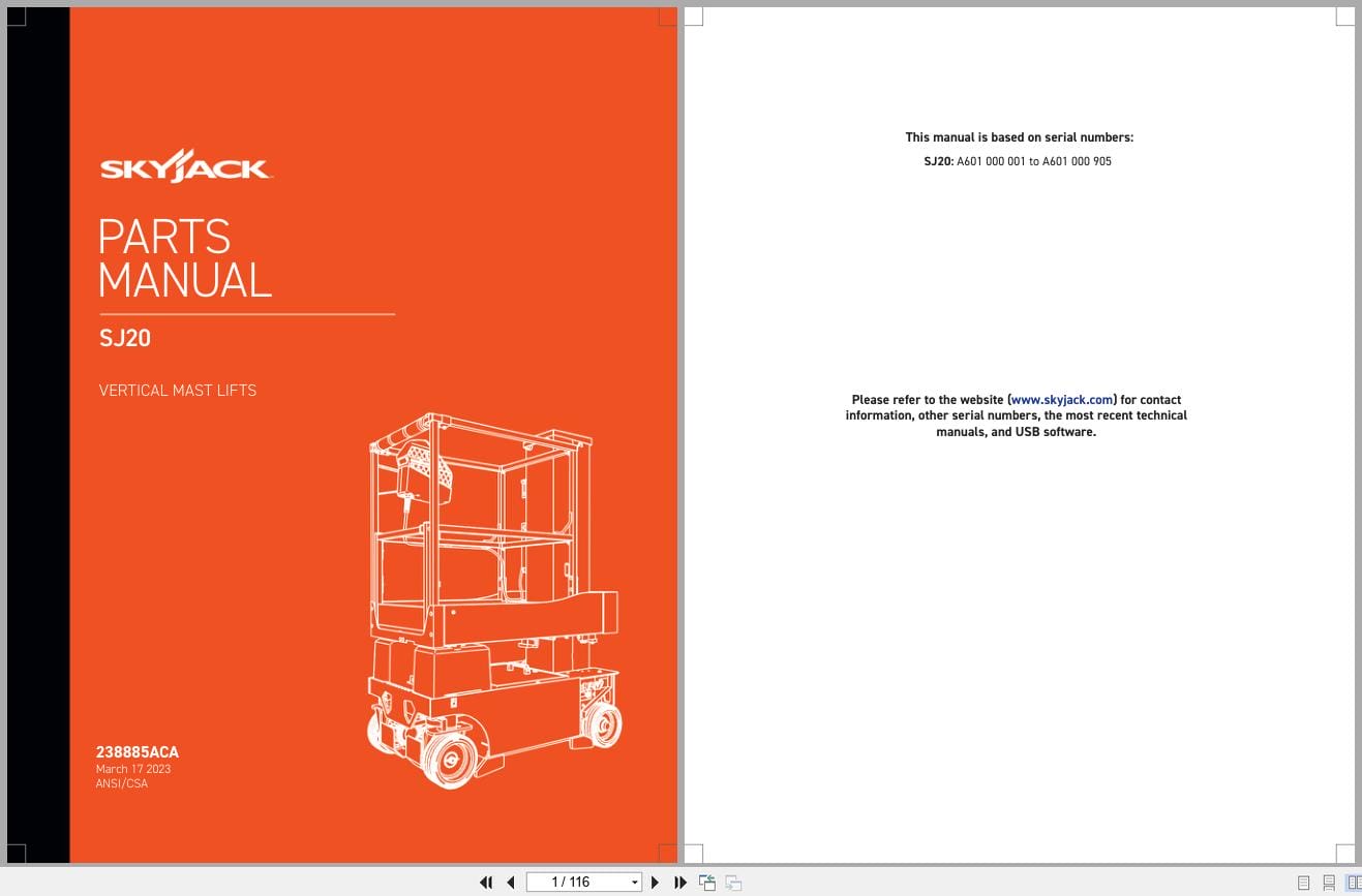
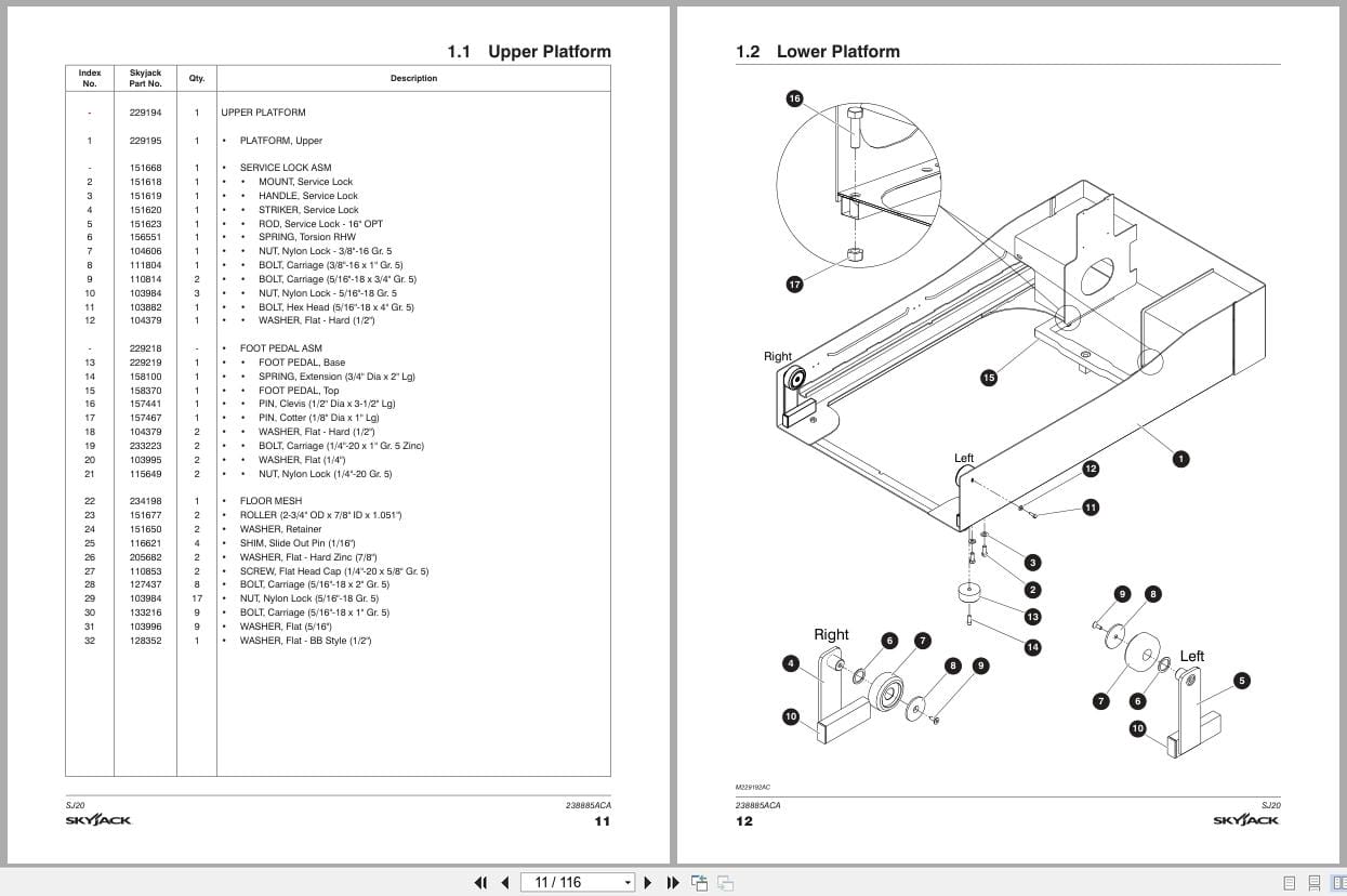
Skyjack Vertical Mast Lifts SJ20 Parts Manual 238885ACA 2023
15 USD -
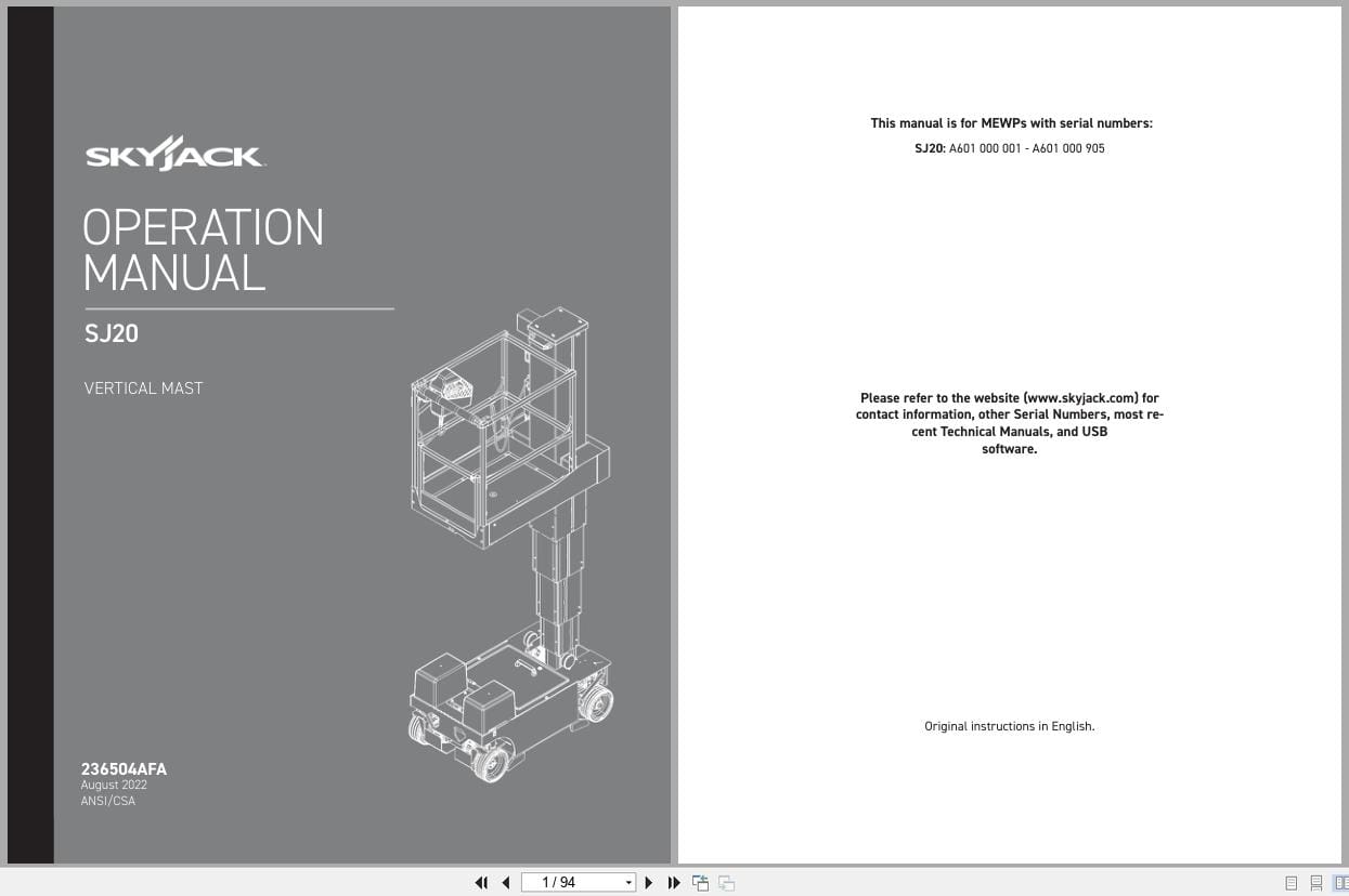
Skyjack Vertical Mast Lifts SJ20 Operating Manual 236504AFA 2022
10 USD -
Skyjack NA 4.93GB PDF Operating Parts Service Manuals
Original price was: 200.140Current price is: 140. USD -
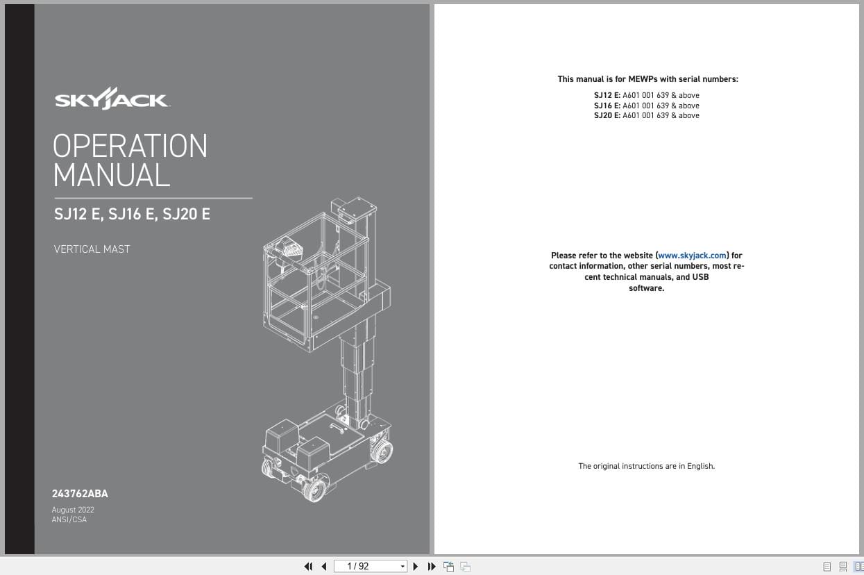
Skyjack Vertical Mast Lifts SJ12E SJ16E SJ20E Operating Manual 243762ABA 2022
10 USD -
Skyjack Vertical Mast Lifts SJ12E SJ16E SJ20E Parts Manual 241913ADA 2023
15 USD -
Skyjack Vertical Mast Lifts SJ12E SJ16E SJ20E Service Manual 241914ADA 2023
20 USD -
Skyjack Vertical Mast Lifts SJ20 Service Manual 238886ADA 2023
20 USD -
Skyjack Lift Aerial Working Platform AWP All Models 2020 Documentation PDF DVD
Original price was: 200.110Current price is: 110. USD