
1 ITEMVIEW CART

Total: 30.00


Expert Support
Full Speed
100% Working
50 USD
Contents:
1 General
1-1 How to use this manual
1-1-1 Construction of this manual
1-1-2 Warning label definition
1-1-3 Major units in use
1-2 Glossary
1-3 Exterior and specifications
1-4 Safety precautions
1-5 Maintenance
1-6 Lubricants
1-6-1 Recommended viscosities and capacities
1-6-2 Oil specifications
1-7 Disassembly/assembly instructions
1-8 Standard torques
1-8-1 Standard torques for bolts and nuts
1-8-2 Standard torques for tightening fittings
2 Transmission
2-1 Overview and specifications
2-1-1 Powertrain components
2-1-2 Power flow
2-2 Torque converter
2-2-1 Exterior and specifications
2-2-2 How it works
2-2-3 Converter stall test
2-3 Transmission body
2-3-1 Exterior and specifications
2-3-2 Tightening torques
2-3-3 How it works (mechanical section)
2-3-4 How it works (hydraulic section)
2-3-5 Transmission pressure test
2-3-6 Inching pedal adjustment
2-3-7 Transmission removal/installation
2-3-8 Transmission disassembly/assembly
2-4 Transmission electric control system
2-4-1 How it works
2-4-2 Electric control system tests
2-5 Troubleshooting
2-5-1 Check list during operation
2-5-2 Check List from Operation Noise
2-5-3 Check List from Pressure Test
3 Drive axle
3-1 Overview
3-1-1 Components and power flow
3-2 General information on drive axle service
3-2-1 Tightening torques
3-2-2 Drive axle oil refill and filter cleaning/replacement
3-3 Drive axle body and accessories
3-3-1 Exterior and specifications (ODB & shoe)
3-3-2 Drive wheel removal/installation
3-3-3 U-joint removal/installation
3-3-4 Drive axle removal/installation
3-4 Wheel hub ass’y (ODB type)
3-4-1 Exterior and specifications
3-4-2 How it works
3-4-3 Wheel hub disassembly/assembly
3-5 Wheel hub ass’y (Shoe type)
3-5-1 Exterior and specifications
3-5-2 How it works
3-5-3 Wheel hub disassembly/assembly
3-6 Differential ass’y
3-6-1 Exterior and specifications
3-6-2 How it works
3-6-3 Differential carrier removal
3-6-4 Differential carrier reassembly
3-7 Troubleshooting
4 Hydraulic system
4-1 Overview
4-1-1 Components
4-1-2 Oil flow
4-2 Main hydraulic pump
4-2-1 Exterior and specifications
4-2-2 How it works
4-2-3 Hydraulic pump removal and installation
4-2-4 Main hydraulic pump disassembly/assembly
4-3 Hydraulic tank and filter
4-3-1 Exterior and specifications
4-3-2 How it works
4-3-3 Suction strainer, return filter, and air breather replacement
4-4 Troubleshooting
5 Lift/tilt/auxiliary system
5-1 Overview
5-1-1 Components
5-1-2 Oil flow
5-2 Control valve
5-2-1 Exterior and specifications
5-2-2 How it works
5-2-3 Relief valve setting
5-2-4 Needle valve use for an emergency lowering
5-2-5 Control valve removal/installation
5-2-6 Control valve disassembly/assembly
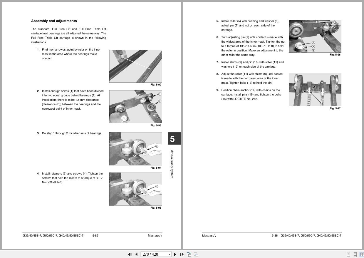
5-3 Mast ass’y
5-3-1 Exterior and specifications
5-3-2 How it works
5-3-3 Forks service
5-3-4 Sideshifter service
5-3-5 Chains service
5-3-6 Tilt cylinders service
5-3-7 Primary lift cylinder service
5-3-8 Standard/secondary cylinders service
5-3-9 Carriage service
5-3-10 Mast service
5-4 Troubleshooting
6 Steering system
6-1 Overview
6-1-1 Components
6-1-2 Oil flow
6-2 Steering control group
6-2-1 Exterior and specifications
6-2-2 How it works
6-2-3 Steering system air removal
6-2-4 Steering system pressure check
6-2-5 Steering wheel removal/installation
6-2-6 Steering column cover removal/installation
6-2-7 Steering unit removal/installation
6-2-8 Steering unit disassembly/assembly
6-3 Steering actuator group
6-3-1 Exterior and specifications
6-3-2 How it works
6-3-3 Rear wheel and tire removal/installation
6-3-4 Rear wheel hub removal/installation/adjustment
6-3-5 Steer axle removal/installation
6-3-6 Tie rod removal/installation
6-3-7 Steering knuckle, kingpin, and bearing removal/installation
6-3-8 Steering cylinder removal/installation
6-3-9 Steering cylinder disassembly/assembly
6-4 Troubleshooting
7 Brake system
7-1 Overview
7-1-1 Components
7-2 Brake pedal
7-2-1 Exterior
7-2-2 How it works
7-2-3 Brake pedal ass’y adjustment
7-2-4 Brake pedal ass’y removal/installation
7-3 Master cylinder (OCDB)
7-3-1 Exterior and specifications
7-3-2 How it works
7-3-3 Brake system air removal
7-3-4 Master cylinder removal/installation
7-3-5 Master cylinder disassembly/assembly
7-4 Parking brake
7-4-1 Exterior
7-4-2 How it works
7-4-3 Adjustment
7-4-4 Brake test
7-4-5 Parking brake lever removal/installation
7-5 Troubleshooting
7-5-1 Master cylinder
7-5-2 Brake system
7-5-3 Parking brake
8 Frame and miscellaneous
8-1 Cabin and overhead guard
8-1-1 Cabin module removal/installation
8-1-2 Overhead guard/full cabin removal/installation
8-2 Seat removal/installation
8-3 Counterweight removal/installation
8-4 Ground speed control
8-4-1 Exterior and specifications
8-4-2 How it works
8-4-3 Removal and installation
8-5 ASC/ASLC
8-5-1 Exterior and specifications
8-5-2 How it works
8-5-3 ASC/ASLC settings
8-5-4 Diagnostic function
8-5-5 Removal and installation
8-6 Functional Safety
8-6-1 Overview
8-6-2 Operation
8-6-3 Exterior
8-6-4 Specification
8-6-5 How it works
8-6-6 Removal & Installation
8-6-7 Calibration on GRYO Sensor
8-6-8 Trouble shooting of New Operator Sensing System
8-7 Air conditioner
8-7-1 Exterior and specifications
8-7-2 How it works
8-7-3 Air conditioner inspection
8-7-4 Disassembly and assembly
8-8 Heater
8-8-1 Exterior and specifications
8-8-2 How it works
8-8-3 Disassembly and assembly
9 Schematics
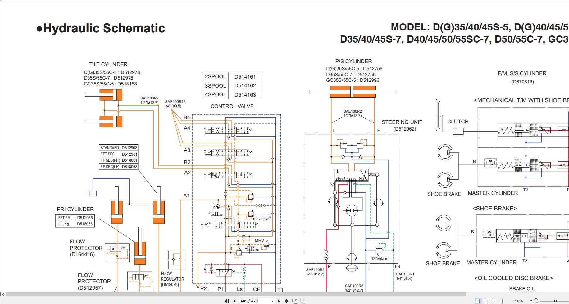
9-1 Hydraulic schematic
9-2 Electric schematic for PSI Engine
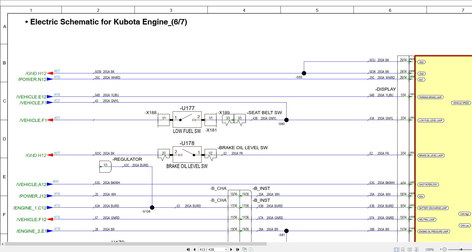
9-3 Electric Schematic for Kubota Engine
ENGINE _1
ENGINE _2
POWER
GND
Vehicle
Display
LAMP
9-4 Electric Schematic for Functional Safety
ENGINE_1
ENGINE_2
POWER
GND
VEHICLE
DISPLAY
LAMP
9-5 Chassis Harness for KUBOTA Engine (310207-09718)
9-6 Chassis Harness for Functional Safety_KUBOTA (310207-12668)
310207-12668 (1/2)
310207-12668 (2/2)
9-7 Instrument Harness for Functional Safety_KUBOTA (310207-12669)
310207-12669 (1/2)
310207-12669 (2/2)
Index

REALEASE :
REALEASE :

REALEASE :
18.09.2021
REALEASE :
18.09.2021

REALEASE :
REALEASE :
REALEASE :
REALEASE :
REALEASE :
REALEASE :

REALEASE :
REALEASE :

REALEASE :
12.04.2019
REALEASE :
12.04.2019

REALEASE :
REALEASE :
Automotive - Heavy Equipment - Truck & Bus - Forklift - Crane