3 ITEMSVIEW CART


Total: 48.00


Expert Support
Full Speed
100% Working
30 USD
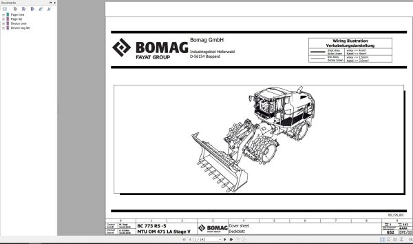
Bomag BC 773 RS-5 MTU OM 471 LA Stage V Function.652 Wiring Diagram 2020 EN DE
Size: 24.1 MB
Format: PDF
Interface: English, German
Brand: Bomag
Type of Manual: Wiring Diagram
Machine: Bomag BC 773 RS-5 MTU OM 471 LA Stage V Machinery
Publicaton: 2020
Function.652
Number Of Page: 142 Pages
Index:
Cover sheet
Table of Contents
Machine index
Notes
Structure identifier overview
Layout mounting locations
Supply
Supply ground
Supply
Fuse protection potential 30
Fuse protection potential 15
Ignition switch, Pre-excitation, Starting unit
Power supply driving controller
Power supply control lever
Power supply display
Power supply sensors
Emergency stop
Disconnecting battery
Communication CAN, Diagnosis
Communication Ethernet
Communication USB
Engine – Reversible fan, Pre-heating, Compressor
Engine – MTU Common Powertrain Controler CPC4
Engine – MTU Motor Control Module MCM2
Engine – MTU Aftertreatment Control Module ACM
Monitoring, Failure indicators
Accelerator pedal, Slope sensor, Backup alarm
Speed sensors
Brake
Speed ranges
Driving pump front left
Driving pump front right
Driving pump rear left
Driving pump rear right
Steering functions
Blade and Shovel functions
Sensors hydraulic cylinders
Engine hood
Central lubrication system
Sockets
Warning horns
Drivers seat
Cabin – Supply
Cabin – Fuse protection
Cabin – Lighting
Cabin – Lighting
Cabin – Cabin equipment
Cabin – Cabin equipment
Cabin – Radio
Cabin – Mirror adjustment
Cabin – Automatic heating and air conditioning
Cabin – Fresh air blower
Back up monitoring
BOMAG Telematics
Interface measurement
Cabin – Additional heater
Device tag list
Terminal strip overview Xl
Terminal strip overview X2
Terminal strip overview X3
Terminal strip overview X4
Terminal strip overview X5
Terminal strip overview X6
Terminal strip overview X7
Terminal strip overview X8
Terminal strip overview X9
Terminal strip overview X1O
Terminal strip overview Xl1
Terminal strip overview Xl2
Description connection points terminals
Terminal line-up diagram Xi
Terminal line-up diagram X2
Terminal line-up diagram X3 – X12
Terminal line-up diagram X7 – Xl1
Plug overview
Pin overview A34
Pin overview A81
Pin overview S259
Pin overview S441
Overview communication CAN 1
Overview communication CAN 2
Overview communication CAN 3
Overview communication CAN Engine
Overview communication CAN 4
Overview central electric
Overview dashboard sidewise
Overview dashboard cabin rear wall

REALEASE :
REALEASE :

REALEASE :
REALEASE :
REALEASE :
REALEASE :

REALEASE :
26.05.2022
REALEASE :
26.05.2022
REALEASE :
REALEASE :
REALEASE :
REALEASE :

REALEASE :
29.09.2022
REALEASE :
29.09.2022

REALEASE :
12.08.2022
REALEASE :
12.08.2022
Automotive - Heavy Equipment - Truck & Bus - Forklift - Crane