
21 ITEMSVIEW CART


Total: 2,115.00
Expert Support
Full Speed
100% Working
20 USD
List of Files:
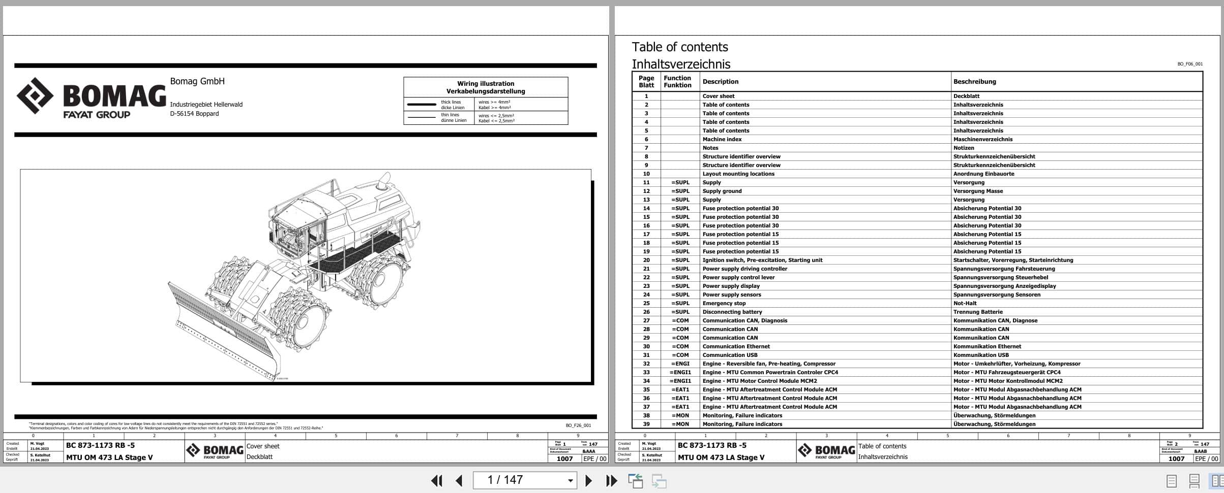
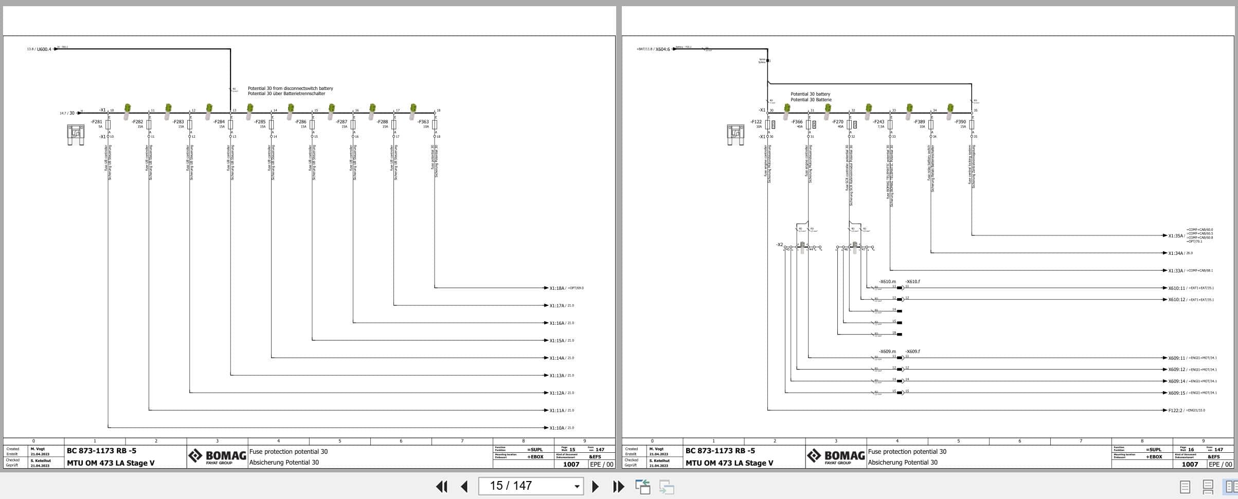
Bomag Refuse Compactor BC 973 RB-5 Electrical Hydraulic Schematic
BC 973 RB-5 101930411001 – 101930419999 (00826035)
000000000000000650_00_000.pdf
Aaa Title Page – Cover Sheet
Cover Sheet
Aab Table Of Contents
Table Of Contents
Adb Structure Identifier Overview
Structure Identifier Overview
Alu Layout Mounting Locations
Layout Mounting Locations
Efs Circuit Diagram
Supl Supply
Com Communication
Engi Engine
Engi1 Engine Mtu Stage 5
Eat1 Exhaust Aftertreatment Mtu Stage 5 – Tier 4F
Mon Monitoring, Failure Indicators
Driv Drive Functions
Ster Steering Functions
Work Working Functions
Comf Comfort Functions
Opt Optional Functions
Epb Device Tag List Electrical Engineering
Device Tag List
Ema1 Terminal Strip Overview
Terminal Strip Overview
Ema2 Terminal Line-Up Diagram
Description Connection Points Terminals
Terminal Line-Up Diagram X1
Terminal Line-Up Diagram X2
Terminal Line-Up Diagram X3 – X12
Terminal Line-Up Diagram X7 – X11
Ema3 Plug Overview
Plug Overview
Efa1 Pin Overview Ecu
Pin Overview A34
Pin Overview A81
Pin Overview S259
Pin Overview S441
Efa2 Overview Can Communication
Overview Communication Can
Etl1 Overview Central Electric
Overview Central Electric
Etl2 Overview Dashboard
Overview Dashboard Sidewise
Overview Dashboard Cabin Rear Wall
000000000000000662_00_000.pdf
Title Page – Cover Sheet
Table Of Contents : 1 – 16
Overview
Drive Circuit Right
Drive Circuit Left
Brake Circuit
Steering And Working Functions
Fan Drive And Hood Opening System
Tank
Gear Box Oil
Device Tag List : A1 – G1
Device Tag List : G2 – Ms15
Device Tag List : Ms16 – Ms33
Device Tag List : Ms34 – Ms51
Device Tag List : P1.1 – V9
Device Tag List : Z1 – Z6
000000000000000813_00_000.pdf
Title Page – Cover Sheet
Table Of Contents : 1 – 16
Overview
Drive Circuit Right
Drive Circuit Left
Brake Circuit
Steering And Working Functions
Fan Drive And Hood Opening System
Tank
Gear Box Oil
Device Tag List : A1 – F8
Device Tag List : G1 – Ms14
Device Tag List : Ms15 – Ms32
Device Tag List : Ms33 – Ms50
Device Tag List : Ms51 – V8
Device Tag List : V9 – Z6
000000000000000814_00_000.pdf
Aaa Title Page – Cover Sheet
Cover Sheet
Aab Table Of Contents
Table Of Contents
Apd Machine Index
Machine Index
Abc Notes
Notes
Adb Structure Identifier Overview
Structure Identifier Overview
Alu Layout Mounting Locations
Layout Mounting Locations
Efs Circuit Diagram
Supl Supply
Com Communication
Engi Engine
Engi3 Engine Cummins Tier 4F
Eat3 Exhaust Aftertreatment Cummins Tier 4F
Mon Monitoring, Failure Indicators
Driv Drive Functions
Ster Steering Functions
Work Working Functions
Comf Comfort Functions
Opt Optional Functions
Epb Device Tag List Electrical Engineering
Device Tag List
Ema1 Terminal Strip Overview
Terminal Strip Overview
Ema2 Terminal Line-Up Diagram
Description Connection Points Terminals
Terminal Line-Up Diagram X1
Terminal Line-Up Diagram X2
Terminal Line-Up Diagram X3 – X12
Terminal Line-Up Diagram X7 – X11
Ema3 Plug Overview
Plug Overview
Plug Overview
Efa1 Pin Overview Ecu
Pin Overview A34
Pin Overview A81
Pin Overview S259
Pin Overview S441
Efa2 Overview Can Communication
Overview Communication Can
Etl1 Overview Central Electric
Overview Central Electric
Etl2 Overview Dashboard
Overview Dashboard Sidewise
Overview Dashboard Cabin Rear Wall
000000000000000879_00_000.pdf
Title Page – Cover Sheet
Table Of Contents : 1 – 16
Overview
Drive Circuit Right
Drive Circuit Left
Brake Circuit
Steering And Working Functions
Fan Drive And Hood Opening System
Tank
Gear Box Oil
Device Tag List : A1 – F8
Device Tag List : G1 – Ms14
Device Tag List : Ms15 – Ms32
Device Tag List : Ms33 – Ms50
Device Tag List : Ms51 – V7
Device Tag List : V8 – Z6
000000000000000890_00_000.pdf
Aaa Title Page – Cover Sheet
Cover Sheet
Aab Table Of Contents
Table Of Contents
Apd Machine Index
Machine Index
Abc Notes
Notes
Adb Structure Identifier Overview
Structure Identifier Overview
Alu Layout Mounting Locations
Layout Mounting Locations
Efs Circuit Diagram
Supl Supply
Com Communication
Engi Engine
Engi1 Engine Mtu Stage 5
Eat1 Exhaust Aftertreatment Mtu Stage 5 – Tier 4F
Mon Monitoring, Failure Indicators
Driv Drive Functions
Ster Steering Functions
Work Working Functions
Comf Comfort Functions
Opt Optional Functions
Epb Device Tag List Electrical Engineering
Device Tag List
Ema1 Terminal Strip Overview
Terminal Strip Overview
Ema2 Terminal Line-Up Diagram
Description Connection Points Terminals
Terminal Line-Up Diagram X1
Terminal Line-Up Diagram X2
Terminal Line-Up Diagram X3 – X12
Terminal Line-Up Diagram X7, X10, X11, X13
Ema3 Plug Overview
Plug Overview
Plug Overview
Efa1 Pin Overview Ecu
Pin Overview A34
Pin Overview A81
Pin Overview A145
Pin Overview S259
Pin Overview S441
Efa2 Overview Can Communication
Overview Communication Can
Etl1 Overview Central Electric
Overview Central Electric
Etl2 Overview Dashboard
Overview Dashboard Sidewise
Overview Dashboard Cabin Rear Wall
000000000000001007_00_000.pdf
Aaa Title Page – Cover Sheet
Cover Sheet
Aab Table Of Contents
Table Of Contents
Apd Machine Index
Machine Index
Abc Notes
Notes
Adb Structure Identifier Overview
Structure Identifier Overview
Alu Layout Mounting Locations
Layout Mounting Locations
Efs Circuit Diagram
Supl Supply
Com Communication
Engi Engine
Engi1 Engine Mtu Stage 5
Eat1 Exhaust Aftertreatment Mtu Stage 5 – Tier 4F
Mon Monitoring, Failure Indicators
Driv Drive Functions
Ster Steering Functions
Work Working Functions
Comf Comfort Functions
Opt Optional Functions
Epb Device Tag List Electrical Engineering
Device Tag List
Ema1 Terminal Strip Overview
Terminal Strip Overview
Ema2 Terminal Line-Up Diagram
Description Connection Points Terminals
Terminal Line-Up Diagram X1
Terminal Line-Up Diagram X2
Terminal Line-Up Diagram X3 – X12
Terminal Line-Up Diagram X7, X10, X11, X13
Ema3 Plug Overview
Plug Overview
Efa1 Pin Overview Ecu
Pin Overview A34
Pin Overview A81
Pin Overview A145
Pin Overview S259
Pin Overview S441
Efa2 Overview Can Communication
Overview Communication Can
Etl1 Overview Central Electric
Overview Central Electric
Etl2 Overview Dashboard
Overview Dashboard Sidewise
Overview Dashboard Cabin Rear Wall
BC 973 RB-5 101930611001 – 101930619999 (00826463)
000000000000000814_00_000.pdf
Aaa Title Page – Cover Sheet
Cover Sheet
Aab Table Of Contents
Table Of Contents
Apd Machine Index
Machine Index
Abc Notes
Notes
Adb Structure Identifier Overview
Structure Identifier Overview
Alu Layout Mounting Locations
Layout Mounting Locations
Efs Circuit Diagram
Supl Supply
Com Communication
Engi Engine
Engi3 Engine Cummins Tier 4F
Eat3 Exhaust Aftertreatment Cummins Tier 4F
Mon Monitoring, Failure Indicators
Driv Drive Functions
Ster Steering Functions
Work Working Functions
Comf Comfort Functions
Opt Optional Functions
Epb Device Tag List Electrical Engineering
Device Tag List
Ema1 Terminal Strip Overview
Terminal Strip Overview
Ema2 Terminal Line-Up Diagram
Description Connection Points Terminals
Terminal Line-Up Diagram X1
Terminal Line-Up Diagram X2
Terminal Line-Up Diagram X3 – X12
Terminal Line-Up Diagram X7 – X11
Ema3 Plug Overview
Plug Overview
Plug Overview
Efa1 Pin Overview Ecu
Pin Overview A34
Pin Overview A81
Pin Overview S259
Pin Overview S441
Efa2 Overview Can Communication
Overview Communication Can
Etl1 Overview Central Electric
Overview Central Electric
Etl2 Overview Dashboard
Overview Dashboard Sidewise
Overview Dashboard Cabin Rear Wall
000000000000000879_00_000.pdf
Title Page – Cover Sheet
Table Of Contents : 1 – 16
Overview
Drive Circuit Right
Drive Circuit Left
Brake Circuit
Steering And Working Functions
Fan Drive And Hood Opening System
Tank
Gear Box Oil
Device Tag List : A1 – F8
Device Tag List : G1 – Ms14
Device Tag List : Ms15 – Ms32
Device Tag List : Ms33 – Ms50
Device Tag List : Ms51 – V7
Device Tag List : V8 – Z6

REALEASE :
REALEASE :

REALEASE :
26.05.2022
REALEASE :
26.05.2022
REALEASE :
REALEASE :

REALEASE :
REALEASE :

REALEASE :
12.08.2022
REALEASE :
12.08.2022

REALEASE :
29.09.2022
REALEASE :
29.09.2022
REALEASE :
REALEASE :

REALEASE :
REALEASE :
 Automotive - Heavy Equipment - Truck & Bus - Forklift - Crane