
5 ITEMSVIEW CART


Total: 185.00
Expert Support
Full Speed
100% Working
10 USD
Contents:
Introduction
The Machine
Intended Use
Warning Symbols
Safety Information
General
Ce Marking And Declaration Of Conformity
Safety – General Instructions
Safety – When Operating
Sitting Position
Work Driving
Driving Near Edges
Special Instructions
Standard Lubricants And Other Recommended Oils And Fluids
Higher Ambient Temperatures, Above +40°C (104°F)
Lower Ambient Temperature – Freeze Risk
Temperatures
High Pressure Cleaning
Fire Fighting
Roll Over Protective Structure (Rops)
Battery Handling
Jump Starting
Technical Specifications
Vibrations – Operator Station
Noise Level
Electrical System
Slopes
Dimensions, Side View
Dimensions, Top View
Weights And Volumes
Working Capacity
General
Co2-Emission
Tightening Torque
Rops – Bolts
Hydraulic System
Machine Description
Diesel Engine
Electrical System
Propulsion System/Transmission
Brake System
Steering System
Rops
Identification
Product Identification Number On The Frame
Machine Plate
Explanation Of 17pin Serial Number
Engine Plates
Decals
Location – Decals
Location – Decals, California
Safety Decals
Info Decals
Fuel
Instruments/Controls
Locations – Instruments And Controls
Locations – Control Panel And Controls
Function Description
Electrical System
Fuses
Fuses In Engine Compartment
Relays
Operation
Before Starting
Battery Isolation Switch – On – Optional
Plus Version
Cc Version
Driver Seat (Cc Version) – Adjustment
Driver Seat (Plus Version) – Adjustment
Instruments And Lamps – Checking
Interlock
Operator Position
Starting
Starting The Engine
Driving
Operating The Roller
Interlock/Emergency Stop/Parking Brake – Check
Vibration
Manual/Automatic Vibration
Manual Vibration – Switching On
Braking
Normal Braking
Emergency Braking
Switching Off
Parking
Chocking The Drums
Master Switch – Optional
Plus Version
Cc Version
Long-Term Parking
Engine
Battery
Air Cleaner, Exhaust Pipe
Sprinkler System
Fuel Tank
Hydraulic Reservoir
Steering Cylinder, Hinges, Etc.
Hoods, Tarpaulin
Miscellaneous
Lifting
Locking The Articulation
Lifting The Roller
Unlocking The Articulation
Transport
Securing Cc800/900/1000 For Loading
Towing/Recovering
Releasing The Brake
Towing The Roller
Operating Instructions – Summary
Preventive Maintenance
Acceptance And Delivery Inspection
Warranty
Maintenance – Lubricants And Symbols
Maintenance Symbols
Maintenance – Maintenance Schedule
Service And Maintenance Points
General
Every 10 Hours Of Operation (Daily)
After The First 50 Hours Of Operation
Every 50 Hours Of Operation (Weekly)
Every 250 / 750 / 1250 / 1750 Hours Of Operation
Every 500 / 1500 Hours Of Operation
Every 1000 Hours Of Operation
Every 2000 Hours Of Operation
Service – Checklist
Maintenance, 10h
Diesel Engine Check Oil Level
Hydraulic Reservoir, Level Check – Filling
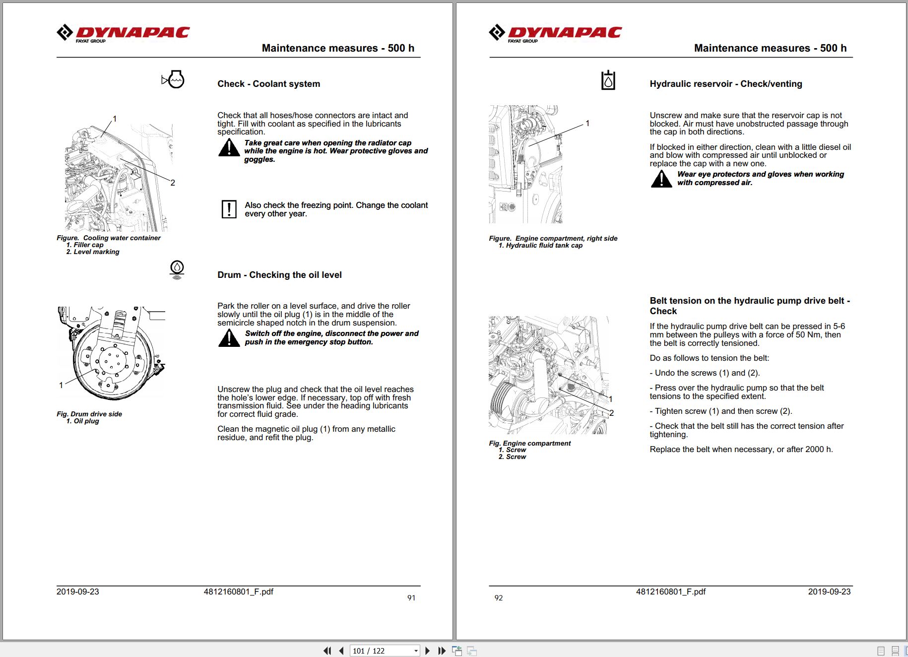
Check – Coolant System
Refueling
Water Tank – Filling
Sprinkler System/Drum
Cleaning Of Sprinkler Nozzle
Sprinkler System – Check, Cleaning
Air Circulation – Check
Scrapers – Check, Adjustment
Warning Lamps – Check
Air Cleaner Indicator
Brakes – Check
Maintenance – 50h
Air Cleaner – Emptying
Rubber Elements And Fastening Screws – Check
Belt Tension On The Hydraulic Pump Drive Belt – Check
Maintenance Measures – 250 H
Air Cleaner – Cleaning – Change
Hydraulic Fluid Cooler – Cleaning
Forward/Reverse Controls And Joints – Check And Lubrication
Maintenance Measures – 500 H
Hydraulic Fluid Cooler – Cleaning
Forward/Reverse Controls And Joints – Check And Lubrication
Air Cleaner – Cleaning – Change
Engine Oil And Oil Filter – Change
Check – Coolant System
Drum – Checking The Oil Level
Hydraulic Reservoir – Check/Venting
Belt Tension On The Hydraulic Pump Drive Belt – Check
Maintenance – 1000h
Hydraulic Fluid Cooler – Cleaning
Forward/Reverse Controls And Joints – Check And Lubrication
Air Cleaner – Cleaning – Change
Engine Oil And Oil Filter – Change
Check – Coolant System
Drum – Checking The Oil Level
Hydraulic Reservoir – Check/Venting
Hydraulic Fluid Filter – Change
Alternator Belt – Checking Tension – Change
Belt Tension On The Hydraulic Pump Drive Belt – Check
Maintenance – 2000h
Hydraulic Fluid Cooler – Cleaning
Forward/Reverse Controls And Joints – Check And Lubrication
Air Cleaner – Cleaning – Change
Engine Oil And Oil Filter – Change
Check – Coolant System
Drum – Checking The Oil Level
Hydraulic Reservoir – Check/Venting
Hydraulic Fluid Filter – Change
Hydraulic Reservoir – Fluid Change
Alternator Belt – Checking Tension – Change
Water Tank – Cleaning
Drum – Changing The Oil
Fuel Tank – Cleaning
Steering Joint – Check
Belt Tension On The Hydraulic Pump Drive Belt – Check
REALEASE :
REALEASE :
REALEASE :
REALEASE :

REALEASE :
REALEASE :

REALEASE :
06.09.2022
REALEASE :
06.09.2022

REALEASE :
26.01.2021
REALEASE :
26.01.2021
REALEASE :
REALEASE :

REALEASE :
26.01.2021
REALEASE :
26.01.2021

REALEASE :
REALEASE :
 Automotive - Heavy Equipment - Truck & Bus - Forklift - Crane