
4 ITEMSVIEW CART


Total: 255.00
Expert Support
Full Speed
100% Working
20 USD
Contents:
Part I Engine
Chapter 1 Engine Assembly (MR479Q, MR479QA, MR481QA)
Section 1 Routine InspectionSection 2 Drive Belt ReplacementSection 3 Valve Clearance AdjustmentChapter 2 Engine Components Replacement
(MR479Q, MR479QA, MR481QA)
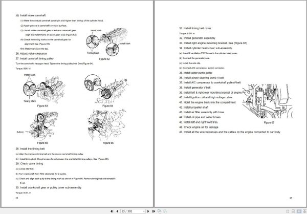
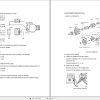
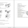
Section 1 Engine ComponentsSection 2 Engine Components ReplacementSection 3 Timing Belt ReplacementSection 4 Camshaft ReplacementSection 5 Cylinder Head Gasket ReplacementSection 6 Oil Pump Oil Seal ReplacementSection 7 Engine Rear Oil Seal ReplacementChapter 3 Lubrication System (MR479Q, MR479QA, MR481QA)
Section 1 Oil Pressure Gage Sensor ReplacementSection 2 Oil Pump Assembly ReplacementSection 3 Oil Filter ReplacementSection 4 Starter ReplacementSection 5 Generator ReplacementChapter 4 Fuel System (MR7131A, MR7151A, MR7161A)
Section 1 Check Fuel System PressureSection 2 Fuel Pump InspectionSection 3 Fuel Injector ReplacementSection 4 Fuel Pump ReplacementSection 5 Fuel Emission Control SystemSection 6 Carbon Canister ReplacementChapter 5 Exhaust System (MR7131A, MR7151A, MR7161A)
Chapter 6 Cooling System Inspection
(MR7131A, MR7151A, MR7161A)
Section 1 System CheckSection 2 Water Pump, Thermostat and Radiator ReplacementChapter 7 Clutch (MR7131A, MR7151A, MR7161A)
Section 1 Clutch ReplacementChapter 8 Maunal Transaxle Assembly
(MR7131A, MR7151A, MR7161A)
Section 1 Manual T ransaxle ReplacementSection 2 Vehicle Speed Sensor ReplacementSection 3 Transmission Case Oil SealSection 4 Transaxle Case Oil Seal ReplacementChapter 9 General Engine Troubles and Their Troubleshooting
Section 1 OverviewSection 2 General Engine Fault and TroubleshootingSection 3 Engine Noise Diagnosis and TroubleshootingChapter 10 Engine Management Unit
Section 1 System DescriptionSection 2 System Component and Working PrinciplePart II Chassis
Chapter 1 Transmission Control Device
Section 1 Transmission Control DeviceSection 2 Lever Type Transmission Control DeviceSection 3 Cable Type Transmissi on Control ModuleChapter 2 Accelerator Pedal
Section 1 Accelerator PedalChapter 3 Clutch Control System
Section 1 Clutch Control SystemSection 2 Clutch Cable Control MechanismSection 3 Clutch hydraulic Control DeviceChapter 4 Propeller Shaft
Section 1 Propeller ShaftChapter 5 Front Suspension System
Section 1 Front Suspension SystemSection 2 Front SuspensionSection 3 Front Wheel AlignmentSection 4 Front Strut AssemblySection 5 Lower Swing Arm AssemblySection 6 Front Stabilizer Bar and Link Rod AssemblyChapter 6 Rear Suspension System
Section 1 Rear Suspension SystemSection 2 Rear SuspensionSection 3 Rear Wheel AlignmentSection 4 Left & Right Rear Strut AssemblySection 5 Rear stabilizer bar assembly, strut rod componentsSection 6 Left & Right Trailing Rod AssemblySection 7 No. 1 Transverse Arm AssemblySection 8 No. 2 Transverse Arm AssemblyChapter 7 Wheel
Section 1 Tire InspectionSection 2 Wheel ReplacementChapter 8 Power Steering System
Section 1 Power Steering SystemSection 2 Steering Drive and Control MechanismSection 3 Steering Pipeline ComponentSection 4 Power Steering Gear Retaining DeviceChapter 9 Brake System
Section 1 Brake SystemSection 2 Brake FluidSection 3 Brake PedalSection 4 Vacuum Booster with Brake Master Cylinder AssemblySection 5 Front Brake AssemblySection 6 Rear BrakeSection 7 Brake LineSection 8 Parking Brake SystemChapter 1 Survey
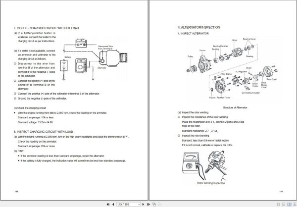
Chapter 2 Starting and Charging System
Section 1 Starting System (MR479Q MR479QA MR481QA)Section 2 Charging System (MR479Q, MR479QA, MR481QA)Chapter 3 Combination Meter System
Section 1 Circuit Diagram of Combination Meter and Location of Multi-pin Plug-in TerminalSection 2 Malfunction Symptom Table and Solution ProcedureSection 3 Combination MeterChapter 4 Wiper and Washer System
Section 1 Wiper and Washer System InspectionSection 2 Replacement and AdjustmentChapter 5 Light System
Section 1 Survey of Light Syst emSection 2 Light System Symptom InspectionSection 3 Headlamp ReplacementSection 4 Front Fog Lamp ReplacementSection 5 Rear Combination Lamp ReplacementSection 6 High Mounted Stop Lamp ReplacementSection 7 Interior Dome Lamp ReplacementSection 8 Rear Row Reading Lamp ReplacementSection 9 License Plate Lamp ReplacementChapter 6 Audio System
Section 1 Audio System DescriptionSection 2 Audio System Connector Terminal LayoutSection 3 Audio System InspectionSection 4 Audio and V ideo System ReplacementChapter 7 SRS (Supplemental Restraint System)
Section 1 SRS-General InformationSection 2 TroubleshootingPart III Electrical Equipment
Section 3 Removal & InstallationChapter 8 MK-20 ABS System
Section 1 ABS DiagnosisSection 2 ABS System CheckSection 3 Removal and InstallationPart IV Air Conditioner and Inside & Outside Trim
Chapter 1 A/C System
Section 1 The Structure & Working Principle of Refrigeration SystemSection 2 Heating SystemSection 3 A/C contr olling systemSection 4 Service Caution & NoticeSection 5 The Refrigeration System Operation ProcedureSection 6 Basic SystemSection 7 A/C System Faults Check & TroubleshootingChapter 2 Inside & outside Trim and Accessor y
Section 1 Configuration Index(I) Outside Trim And Fr ont Accessory(II) Outside Trim and Rear Accessory(III) Front inside trim(IV) Rear inside trimSection 2 Inside & Outside Trim and Accessories Removal and Installation(I) Front Bumper(II) Engine Hood(III) Outside Rear View Mirror(IV) Rear trunk Lid(V) Rear Bumper(VI) Seat Removal, Installation and Adjustment(VII) Seat Belt(VIII) Instrument panel and auxiliary console(IX) A pillar inside trim and front door sill(X) B pillar inside trim(XI) Cpillar inside trim and rear door sill(XII) Roof inside trim(XIII) Carpet and Heat Insulator(XIV) Rear trunk Inside Trim(XV) Engine Hood Inside Trim(XVI) DoorPart V BodyChapter 1 General Information
Section 1 Body StructureChapter 2 Body Repair
Section 1 Body Damage Forms and Requirements for RepairSection 2 Typical Technology Of Body Panel RepairSection 3 Repair after Body DamageSection 4 Features and Composition of Automobile BodySection 5 Painting Technique after Body RepairSection 6 Service Data For Body
REALEASE :
REALEASE :
REALEASE :
REALEASE :

REALEASE :
REALEASE :
REALEASE :
REALEASE :

REALEASE :
REALEASE :

REALEASE :
REALEASE :
REALEASE :
REALEASE :
REALEASE :
REALEASE :
 Automotive - Heavy Equipment - Truck & Bus - Forklift - Crane