
6 ITEMSVIEW CART


Total: 1,390.00

Expert Support
Full Speed
100% Working
15 USD
Contents:
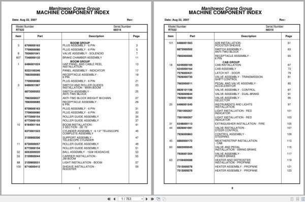
Plug Assembly – 6 Pin
Valve Assembly – Solenoid
Brake Chamber Assembly
Hap Panel And Cable Reel Installation
Panel Assembly – Indicator
Receptacle Assembly – 6 Pin
Switch And Roller Guides Installation – Main Boom
Switch Assembly – Anti-Two Block
Anti-Two Block Weight W/Chain
Roller Guide Assembly
Boom Installation – 3 Section – 28’-70’
Cylinder Assembly – 6 1/2″ Telescope Complete Assembly
Support Assembly – Telescope Cylinder
Ball Assembly – 150# Headache
Carrier Installation – Jib Boom
Light Installation – Boom
Sheave Installation – Rooster
A2b Installation – Rooster Sheave
Cab Installation
Cab Assembly
Latch Kit – Door
Valve Assembly – Transmission Shift Control
Pedal And Valve Assembly – Accelerator
Valve Assembly – Control
Valve Assembly – Dual Brake
Valve Assembly – Selector
Instruments And Lights Installation
Light Installation – Red Indicator
Extinguisher Installation – Fire
Valve Installation – Steer Control
Control Assembly – Steering
Weatherstrip Installation – Cab
Valve And Pedal Installation – Swing Brake
Valve Assembly – Power Brake
Heater And Defroster Installation – Propane
Heater Assembly – Propane
Seat Installation
Seat Assembly
Fan Installation – Cab Circulating
Fan Assembly – 12 Volt Cab Complete Assembly
Acoustical Installation
Wiper And Washer Installation – Windshield
Warning System Installation -Audio/Visual
Grab Rail Installation
Air Lines Installation
Control Valve And Linkage Installation
Valve Bank Assembly – 1 Section
Valve Assembly – Outlet
Valve Section – Inlet (A-35 Series)
Valve Assembly – Relief 2250 Psi
Cartridge Assembly
Valve Bank Assembly – 2 Section (A-20 Series)
Valve Assembly – Section Inlet (A-20 Series)
Valve Assembly – Section Outlet (A-20 Series)
Valve Bank Assembly – 3 Section (A-35 Series)
Valve Assembly – Relief 1000 Psi
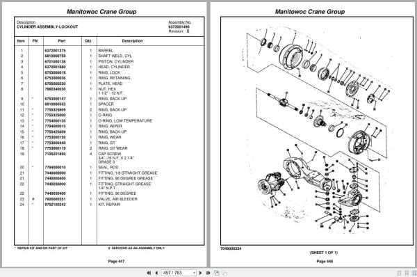
Cylinder Assembly – Lockout
Panel Installation – Hydraulic Test
Hydraulic Lines Installation – Pressure Check Panel
Valve Installation – Lever Lockout Solenoid
Hydraulic Lines Installation – Lift
Hydraulic Lines Installation – Mid Telescope
Hydraulic Lines Installation – Main Hoist
Hydraulic Lines Installation – Lever Lockout
Hoist Installation – Main
Hoist Assembly – Low Profile
Hoist Assembly
Valve Assembly – Motor Control
Brake Assembly
Gear Reduction Assembly
Motor Assembly – Hydraulic Vane Type
Rotation Indicator Installation
Driver Assembly Driver Assembly
Indicator Assembly
Transmitter Assembly
Idler Drum And Cable Follower Installation
Cable Follower
Idler Drum Assembly
Hose Clamp Installation
Turntable Drive Installation
Swing Box Assembly – Complete
Swing Box And Brake Assembly
Brake Assembly – Swing
Motor Assembly – Orbit
Counterweight Installation
Cylinder Installation – 9.00’’ Lift
Cylinder Assembly – 9″ Lift
Swivel Installation – Electric/Air/Hydraulic
Swivel Assembly – Hydraulic
Swivel Assembly – Air/Hydraulic
Slip Ring Assembly – 35 Conductor
Bearing Bolt Installation
Lock Installation – Swing
Cover Plate Installation
Valve Installation – Flow Divider
Valve Assembly – Flow Divider
Guard Installation – Pinion
Valve Installation – Reducing/Relief (Swing)
Valve Assembly – Pressure And Sequence
Brake Valve And Air Tank Installation
Hydraulic Schematic – Free Swing
Hydraulic Lines Installation – Non-Free Swing
Valve Assembly – Shuttle
Pivot Shaft Installation – Boom
Engine Installation – Deutz
Filter Assembly – Oil
Pump Assembly – Steer
Cylinder Assembly – Throttle
Battery Installation
Quick Start Installation
Transmission Installation
Transmission Assembly
Transmission Assembly Front Cover And Case Assembly
Transmission Assembly Clutch And Gear Group
Transmission Assembly Axle Disconnect Assembly
Transmission Assembly Low Clutch Assembly
Transmission Assembly Forward Clutch Assembly
Transmission Assembly Reverse And Second Shift
Transmission Assembly Control Valve Assembly
Cylinder Assembly – Air Lockout
Valve Assembly Transmission
Driveline Installation
Driveline Assembly
Driveline
Transmission And Converter Lines Installation
Transmission Shift Lines Installation
Axle Installation – Front
Axle Assy Clark Front
Axle Assy. Housing & Hub Group
Axle Assy. Diff. Carrier Group
Axle Assy. Park Brake Group
Axle Assy. Spider Assy. Group
Axle Assy. Brake Assy. Group
Cylinder Assembly – 3″ Steer
Axle Installation – Rear
Cylinder Assembly -Lockout
Axle Assembly
Axle Assy. Housing & Hud Group
Axle Assy . Diff.Carrier Group
Cylinder Assembly – Steer Complete Assembly
Tire And Wheel Assembly
Indicator Installation – Rear Steer
Switch Assembly – Limit
Outrigger Beam Installation
Cylinder Assembly – 5 1/2″ Stabilizer
Cylinder Assembly – Extension
Outrigger Valve Installation
Valve Assembly – Outrigger Selector Complete Assembly
Valve Assembly – 4 Stack Outrigger Solenoid
Valve Assembly – Sequence
Float Assembly – Outrigger
Frame – Fifth Wheel Assembly
Hood Installation – Engine
Reservoir Installation – Hydraulic
Fuel Tank Installation
Air Tanks And Valves Installation
Valve Assembly – Check
Actuator Assembly – Air Hydraulic
Air System Schematic
Lights Installation
Mirror Installation -Rear View
Battery Box Installation
Electrical System Installation – Carrier
Cover Installation – Pump
Tool Box Installation
Cover Installation – Front
Fender Installation
Alarm Installation – Back-Up
Tie Down Installation – Hook Block
Hydraulic Lines Installation – Supply, Pressure And Return
Decal Installation
Valve Installation – Rear Axle Lockout
Valve Assembly
Hydraulic Brake Lines Installation
Valve Installation – Relief (Power Steering)
Valve Assembly – Relief (See Separate Parts List)
Hydraulic Lines Installation – Outrigger
Hydraulic Lines Installation – Front Steer
Hydraulic Lines Installation – Rear Steer
Hydraulic Schematic – Rear Axle Lockout

REALEASE :
REALEASE :

REALEASE :
REALEASE :

REALEASE :
REALEASE :

REALEASE :
REALEASE :

REALEASE :
REALEASE :

REALEASE :
REALEASE :

REALEASE :
REALEASE :

REALEASE :
REALEASE :
 Automotive - Heavy Equipment - Truck & Bus - Forklift - Crane