
17 ITEMSVIEW CART


Total: 3,690.00
Expert Support
Full Speed
100% Working
30 USD
Contents:
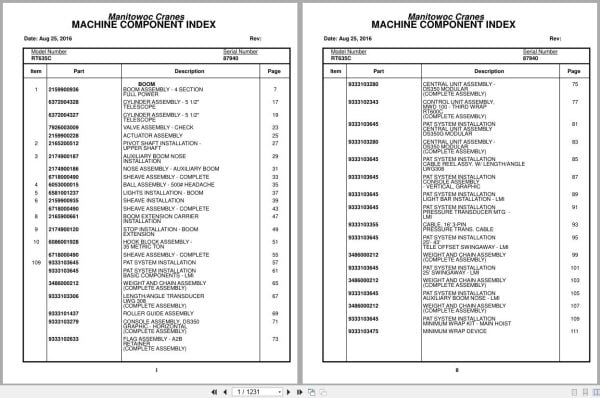
Boom Assembly – 4 Section Full Power
Cylinder Assembly – 5 1/2″ Telescope
Valve Assembly – Check
Actuator Assembly
Pivot Shaft Installation – Upper Shaft
Auxiliary Boom Nose Installation
Nose Assembly – Auxiliary Boom
Sheave Assembly – Complete
Ball Assembly – 500# Headache
Lights Installation – Boom
Sheave Installation
Boom Extension Carrier Installation
Stop Installation – Boom Extension
Hook Block Assembly – 35 Metric Ton
Pat System Installation
Pat System Installation Basic Components – Lmi
Weight And Chain Assembly (Complete Assembly)
Length/Angle Transducer Lwg 308
Roller Guide Assembly
Console Assembly , Ds350 Graphic – Horizontal
Flag Assembly – A2b Retainer
Central Unit Assembly – Ds350 Modular
Control Unit Assembly , Mwd 100 – Third Wrap
Pat System Installation Central Unit Assembly
Pat System Installation Cable Reel Assy. W/ Length/Angle
Pat System Installation Console Assembly
Pat System Installation Light Bar Installation – Lmi
Pat System Installation Pressure Transducer Mtg –
Cable, 16′ 3-Pin Pressure Trans. Cable
Pat System Installation 25′- 43′
Pat System Installation 25′ Swing Away – Lmi
Pat System Installation Auxiliary Boom Nose – Lmi
Pat System Installation Minimum Wrap Kit – Main Hoist
Minimum Wrap Device
Pat System Installation Sensor, Minimum Wrap W/Notch
Pat System Installation Control Unit Assembly – Mwd100
Pat System Installation Minimum Wrap Kit, Aux Hoist
Pat System Installation Cable Assembly – Jumper 7′
Pat System Installation Flag Assembly – A2b Retainer
Pat System Installation Anti 2 Block Weight Assembly
Pat System Installation Decals Assembly
Pat System Installation Wiring Diagrams
Hydraulic Lines Installation – Telescope
Hydraulic Lines Installation – Hydraulic Heater
Hydraulic Lines Installation – Brake
Hydraulic Lines Installation – Supply, Pressure And Return
Hydraulic Lines Installation – Front Steer
Valve Assembly – Residual Check
Valve Installation – Control (Main And Auxiliary Hoist)
Valve Assembly – 2 Section Control
Valve Assembly – 2 Section
Valve Assembly – 1 Section Control
Brake Booster And Master Cylinder Assembly
Cylinder Assembly – Brake Booster And Master
Valve Assembly – Pressure Reducing
Valve Assembly – Flow Control
Valve Assembly – Sequence
Valve Assembly – 5 Station Solenoid
Hydraulic Lines Installation – Pressure Check Panel
Hoist Installation – Main And Auxiliary
Hoist Assembly – Complete
Hoist Assembly
Group Assembly – Right Hand
Group Assembly – Left Hand
Center Group – Hoist
Motor Assembly – Hydraulic Vane Type (Complete Assembly)
Brake Assembly
Valves And Plumbing Installation
Valve Assembly – Control
Cable Follower And Idler Drum Assembly
Kicker Installation
Hydraulic Lines Installation – Main And Auxiliary Hoist
Sensor Installation – Hoist Rotation
Rotation Sensor Assembly
Harness Assembly – Rotation Sensor
Mirror Installation – Hoist
Hydraulic Lines Installation – Main And Auxiliary Hoist
Turntable Drive Installation
Box Assembly – Swing Complete
Swing Box And Brake Assembly
Brake Assembly – Swing (Complete Assembly)
Motor Assembly – Orbit
Lock Assembly – Swing
Pin Installation – Turntable Lock Installation
Lower Shaft And Lift Cylinder Installation
Cylinder Assembly – 10.00” Lift
Positive Swing Lock Installation
Lever Installation
Swivel Installation – Electrical And Hydraulic
Swivel Assembly – Electrical And Hydraulic
Swivel Assembly – 15 Port Hydraulic
Ring Assembly – 44 Conductor Slip
Hydraulic Lines Installation – Swing
Hydraulic Lines Installation – Lift
Sensor Installation – Swing Lock Pin Position
Switch Assembly
Lube Installation – Turntable Auto Bearing
Pump Assembly – Grease
Valve Assembly – Park Brake (Complete Assembly)
Valve Assembly – Divide
Bearing Bolt Installation
Hydraulic Lines Installation – Swing And Swing Brake
Switch Installation – Axle Oscillation Override
Cab Installation
Cab Assembly
Cab Section
Valve Assembly – Treadle
Cable Assembly – Control
Motor Assembly – Wiper (Complete Assembly)
Door Assembly
Skylight Assembly – Sliding
Column Assembly – Steering (Complete Assembly)
Valve Assembly – Orbital (W/O Return To Center Steering)
Valve Installation – Hydraulic Heater
Valve Assembly – Solenoid
Valve Assembly – Relief 2500 Psi
Heater Valve Installation
Console Installation – Front
Console Assembly – Front
Control Assembly – Shift
Gauge Cluster – 12v
Harness Installation
Harness Assy, Outrigger Cab To Board
Cable Assembly – Wiper Motor
Seat Installation – Control Single Axis With Auxiliary
Control Seat Assembly – Single Axis
Seat Assembly
Plate Assembly
Controller Assembly – Single Axis
Harness Assembly – Seat Arm
Harness Assembly – Seat
Suspension Assembly – Seat
Covers Installation – Bottom
Pedal Installation – Swing Brake
Screen Installation – Sun Open Mesh
Heater Installation – Hydraulic
Heater Assembly
Heater Panel Installation
Harness Assembly – Heater Panel
Work Light Installation
Extinguisher Installation – Fire
Electrical System Installation – Cab
Harness Assembly – Cab
Cable Assembly – Skylight Wiper Motor
Panel Assembly
Harness Assembly – Panel Assembly
Mat Installation – Floor
Acoustical Installation
Wiper/Washer Installation – Skylight
Washer Installation – Windshield
Pedal Installation – Boom Telescope
Rocker Pedal – Single Function
Fan Installation – Cab Circulating
Fan Assembly – 12 Volt Cab (Complete Assembly)
Hydraulic Lines Installation – Heater
Electrical System Installation – Superstructure
Harness Assembly – Superstructure
Hydraulic Heater Lines
Cooler Installation – Oil
Fan Assembly
Engine Installation – (For Reference Only)
Engine Assembly – Cummins 6bt5.9
Transmission Installation – Cummins/Clark
Transmission Assembly – Complete
Transmission Assembly
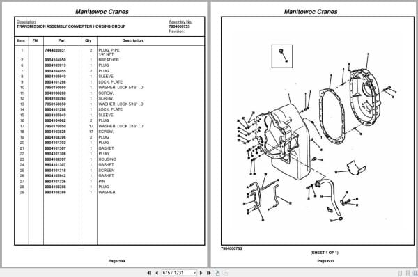
Transmission Assembly Converter Housing Group
Transmission Assembly Transmission Case And
Transmission Assembly Turbine Shaft Stator Support
Transmission Assembly Torque Converter Assembly
Transmission Assembly Auxiliary Pump Drive Parts
Transmission Assembly Charging Pump Drive Group
Transmission Assembly Forward Shaft Group
Transmission Assembly Reverse Idler Group
Transmission Assembly Reverse And Second Shaft
Transmission Assembly Low Speed Shaft Group
Transmission Assembly Forward And Hi 3rd And 4th
Transmission Assembly Idler Shaft Group
Transmission Assembly Output Shaft Group
Transmission Assembly Drive Plate Group
Transmission Assembly Control Valve Group
Transmission Assembly Control Valve Assembly
Transmission Assembly Disconnect Assembly – Pump
Transmission Assembly Charging Pump And Filter
Pump Assembly – Two Section Gear
Pump Assembly
Cylinder Assembly – Throttle (Complete Assembly)
Electrical Systems Installation
Harness Assembly – Engine
Disconnect Assembly – Pump
Engine Components Assembly
Quick Start Installation
Belt & Filter Cumm Cta 8.3
Cleaner Installation – Air
Cleaner Assembly – Air (Complete Assembly)
Exhaust System Installation
Radiator Installation
Radiator Assembly
Hood Installation – Engine Cummins
Engine Hood Weld And Assembly – Cummins
Weatherstrip Installation – Engine Hood
Battery Installation
Cover Installation – Battery
Divider Installation – Flow
Divider Assembly – Flow
Driveline Installation
Driveline Assembly
Shaft Assembly – Drive
Axle Installation – No Spin Front
Axle Assembly – No-Spin Front
Drive/Steer Axle
Drive/Steer Axle Differential Carrier Assembly
Drive/Steer Axle Housing Assembly
Drive/Steer Axle Wheel End Assembly
Drive/Steer Axle Caliper Assembly
Cylinder Assembly – 3″ Steer
Chamber Assembly – Brake
Axle Installation – Rear
Axle Assembly – Rear
Axle Assembly – Drive/Steer
Axle Assembly – Drive/Steer Carrier Assembly
Axle Assembly – Drive/Steer Housing Assembly
Axle Assembly – Drive/Steer Wheel End Parts
Axle Assembly – Drive/Steer Caliper Assembly
Cylinder Assembly – 5″ Lockout
Hydraulic Lines Installation – Rear Axle Lockout
Hydraulic Lines Installation – Rear Steer
Tire And Wheel Assembly
Indicator Installation – Rear Steer
Valve Installation – Rear Axle Lockout
Hydraulic Lines Installation – Steer
Outrigger Beam Installation
Beam Assembly – Outrigger
Cylinder Assembly -4 1/2″ Outrigger Jack (Complete Assembly)
Cylinder Assembly – 2 1/2″ Outrigger Extension
Hydraulic Lines Installation – Outrigger
Outrigger Float Stowage Installation
Float Assembly – Outrigger
Outrigger Control Valve Installation
Valve Assembly – 4 Stack Outrigger Solenoid
Valve Assembly
Frame Section
Stud Installation
Stud Installation – Weld (Not Available As Assembly)
Electrical System Installation
Harness Assembly – Carrier
Box Assembly – Relay
Harness Assembly – Relay Box
Exterior Lights Installation – Carrier
Mirror Installation – Frame
Fender Installation
Hydraulic Reservoir Installation
Reservoir Assembly – Hydraulic
Cover Assembly – 16 1/4″ Inspection Inspection
Filter Assembly – Return
Flex Step Installation
Fuel Tank And Step Installation
Tank Assembly – 60 Gallon Fuel
Tie Down Installation – Hook Block
Tool Box Installation
Decking Installation
Filter Installation – Fuel/ Water Separator
Relief Valve And Parking Brake Installation
Valve Assembly – Relief
Decal Installation – Rt635c

REALEASE :
REALEASE :

REALEASE :
REALEASE :

REALEASE :
REALEASE :

REALEASE :
REALEASE :

REALEASE :
REALEASE :

REALEASE :
REALEASE :

REALEASE :
REALEASE :

REALEASE :
REALEASE :
 Automotive - Heavy Equipment - Truck & Bus - Forklift - Crane