
25 ITEMSVIEW CART


Total: 2,695.00
Expert Support
Full Speed
100% Working
15 USD
Contents:
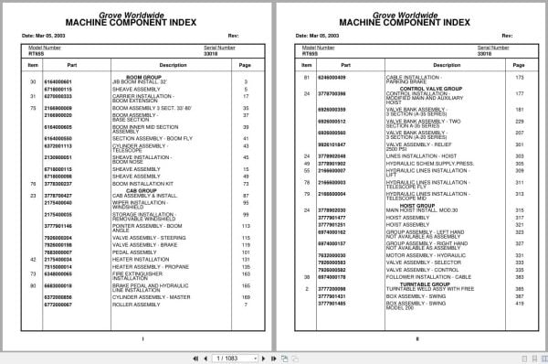
Grove Worldwide
Jib Boom Install. 32’
Sheave Assembly
Roller Assembly
Sheave Wheel Assembly
Carrier Installation – Boom Extension
Support Assembly – Front Jib
Boom Assembly 3 Sect. 33’-80’
Boom Assembly – Base Section
Boom Inner Mid Section Assembly
Section Assembly – Boom Fly
Cylinder Assembly – Telescope
Sheave Installation – Boom Nose
Support Assembly – Cylinder
Support Assembly – Cylinder (3 Section Boom)
Boom Installation Kit
Cab Assembly & Install.
Wiper Installation – Windshield
Valve Assembly – Horn
Storage Installation – Removable Windshield
Pedal Assembly
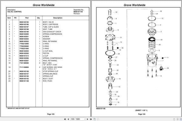
Valve, Control
Valve Assembly – Control
Boom Pointer/Angle Indicator Assembly
Pointer Assembly – Boom Angle
Valve Assembly – Steering
Valve Assembly – Brake
Heater Installation
Heater Assembly – Propane
Fire Extinguisher Installation
Brake Pedal And Hydraulic Line Installation
Cylinder Assembly – Master
Cable Installation – Parking Brake
Cable Assembly – Brake
Control Installation – Modified Main And Auxiliary
Valve Bank Assembly – 3 Section (A-35 Series)
Valve Section – Inlet (A-35 Series)
Valve Assembly – Outlet
Valve Assembly – 4-Way Section (A-35 Series)
Valve Section – Relief
Valve Assembly – Relief
Valve Section – 4 Way (A-35 Series)
Cartridge Assembly
Valve Bank Assembly – 3 Section (A-20 Series)
Valve Assembly – Section Inlet (A-20 Series)
Valve Assembly – Relief 2500 Psi
Valve Assembly – Section Outlet (A-20 Series)
Valve Section – 4 Way
Valve Bank Assembly – Two Section A-35 Series
Lines Installation – Hoist
Hydraulic Schem.Supply.Press.
Hydraulic Lines Installation – Lift
Hydraulic Lines Installation – Telescope Fly
Hydraulic Lines Installation – Telescope Mid
Main Hoist Install. Mod.30
Hoist Assembly
Group Assembly – Left Hand Not Available As Assembly
Group Assembly – Right Hand Not Available As Assembly
Motor Assembly – Hydraulic
Valve Assembly – Selector
Follower Installation – Cable
Turntable Weld Assy With Free
Box Assembly – Swing
Box Assembly – Swing Model 200
Swing Box Assembly – Model 200
Brake Assembly – Disc
Brake Assembly – Mechanical
Motor Assembly – Orbit
Swivel Installation – Hydraulic
Swivel Assembly
Swivel Assembly – Hydraulic
Swivel Assembly – 10 Port
Slip Ring Assembly
Manifold Installation – Hydraulic
Cylinder Installation – Lift
Cylinder Assembly – Lift
Cylinder Assembly – 7″ Lift
Hose Reel Installation
Reel Assembly – Hose
Hose Reel Assy. 25″ Dia.
Reel Assembly – Right Hand Automatic
Emergency Air Tank Install.
Elevation And Swing Warning Installation
Switch Assembly – Limit
Swing Hyd. Schematic
Valve Bank Assembly – 1 Section (A-20 Series)
Valve Assembly – Relief 1500 Psi
Boom Pivot Bearing Parts
Pivot Shaft Installation – Boom
Engine Installation – Cummins
Engine Assembly – Cummins V555
Converter Assembly – Torque
Pump Assembly – Steer
Throttle Installation – Cummins V-555-C
Cylinder Assembly – Throttle
Disconnect Assembly – Pump
Pump Assembly
Radiator And Oil Cooler Installation
Air Cleaner Installation
Air Cleaner Assembly
System Installation – Exhaust
Hood Assembly – Engine
Quick Start Installation
Wiring Diagram – Hourmeter
Clutch/Lube Oil Pressure Check Point Installation
Transmission Installation
Transmission Assembly
Valve Assembly – Transmission Shift Control
Transmission Assembly Valve Assembly –
Driveline Assembly
Front Driveline Installation
Rear Axle & Range Shifter
Rear Axle And Range Shift Assembly
Cylinder Assembly – Air
Valve Assembly – 3-Way Solenoid
Hyd.Trans&Torq.Conv.Lines Inst
Front Axle Installation
Axle Assembly
Axle Assembly Axle
Chamber Assembly – Camtite
Axle Assembly Planet Spider Assembly
Axle Assembly Tie Rod Assembly
Axle Assembly Differential And Carrier
Axle Assembly Air Brake Assembly
Cylinder Assembly – 4.00’’ Steer
Rear Axle Installation
Axle Assembly – Rear Drive Steer
Cylinder Assembly – 6.00’’ Lockout
Cylinder Assembly – 3.00’’ Steer
Outrigger Assembly – Hydraulic
Cylinder Assembly – Stabilizer
Cylinder Assembly – Outrigger
Float Assembly – Outrigger Aluminum
Cylinder Assembly – 3.00’’ Outrigger
Valve Assembly – In-Line Relief
Valve Assembly – 4 Stack Outrigger Solenoid
Tire And Wheel Assembly
Valve Installation – Rear Axle Lockout
Valve Installation – Front Steer
Valve Assembly – Relief (See Separate Parts List)
Rear Axle Lockout Override Installation
Valve Assembly – Solenoid
Hydraulic Schem. Front Steer
Hydraulic Schem. Rear Steer
Axle Lockout With Override Hydraulic Schematic
Outrigger Hyd Sch.
Valve, Pressure Relief
Lines Installation – Air Brake And Throttle
Valve Assembly – Check
Tank Installation – Fuel
Air Tanks, Valves, And Cover Installation
Valve Assembly – Quick Release
Valve Assembly – Relay
Front Deck Cover And Storage Well Installation
Terminal Block Assembly
Light And Turn Signal Installation
Fenders And Storage Well Assembly And Installation
Hyd.Tank & Decking Install.
Deck And Hydraulic Tank Assembly
Filter Assembly – Oil
Wiring Diagram Schematic

REALEASE :
REALEASE :

REALEASE :
REALEASE :

REALEASE :
REALEASE :

REALEASE :
REALEASE :

REALEASE :
REALEASE :

REALEASE :
REALEASE :

REALEASE :
REALEASE :

REALEASE :
REALEASE :
 Automotive - Heavy Equipment - Truck & Bus - Forklift - Crane