
5 ITEMSVIEW CART


Total: 340.00
Expert Support
Full Speed
100% Working
15 USD
Contents:
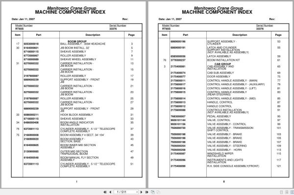
Ball Assembly – 300# Headache
Jib Boom Install. 32’
Sheave Assembly
Roller Assembly
Sheave Wheel Assembly
Carrier Installation – Jib Boom
Support Assembly – Front Jib
Hook Block Assembly
Boom Angle Indicator Installation
Cylinder Assembly – 5 1/2 ” Telescope Complete Assembly
Boom Assembly 4 Sect. 34’-104’
Boom Assembly – Section, Base
Boom Inner Mid Section Assembly
Outer Mid Section Trapezoidal Boom
Boom Manual Fly Section Assembly
Support Assembly – Cylinder
Latch And Cylinder Support Installation
Latch Assembly
Boom Installation Kit
Cab Assembly And Installation
Cab Sub Assembly
Door Assembly
Control Handle Assembly – (Main)
Control Handle Assembly – (Auxiliary)
Control Handle Assembly – (Lift)
Control Handle Assembly (Rear Steering)
Control Handle Assembly – (Mid)
Handle, Control
Handle Control
Controls Installation (Not Available As Assembly )
Pedal Assembly
Valve, Control
Valve Assembly – Control
Valve Assembly – Transmission Shift Control
Valve Assembly – Brake
Valve Assembly – Steering
Valve Assembly – Horn
Windshield Wiper Installation
Instruments And Lights Installation
R.H. Side Console Assembly (Front)
R.H. Side Console Assembly – Front
Console Panel Assembly
Panel – Right Hand Side Front
Lock Installation – Window (Not Available As Assembly )
Hydraulic Lines Installation
Acoustical Installation
Cable Installation – Parking Brake
Cable Assembly – Brake
Hydraulic Lines Installation – Swing
Lines Installation – Hoist
Control Valve And Linkage Installation
Valve Bank Assembly – 4 Section (A-35 Series)
Valve Section – Inlet (A-35 Series)
Valve Assembly – Outlet
Valve Sub- Assembly – Relief
Cartridge Assembly – Relief Valve
Valve Assembly – 4-Way Section (A-35 Series)
Valve Section – Relief
Valve Assembly – Relief
Valve Section – 4 Way (A-35 Series)
Cartridge Assembly
Valve Bank Assembly – 1 Section (A-20 Series)
Valve Assembly – Section Inlet (A-20 Series)
Valve Assembly – Section Outlet (A-20 Series)
Valve Section – 4 Way
Valve Assembly – Relief 1500 Psi
Valve Bank Assembly – 3 Section (A-20 Series)
Valve Assembly – Relief 2500 Psi
Valve Bank Assembly – 1 Section (A-35 Series)
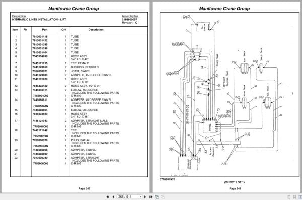
Hydraulic Lines Installation – Lift
Lines-Supply,Press& Return Hyd
Telescope Fly, Hyd.Schematic
Grove Mod 30a Hoist-Main Install
Hoist Assembly – Model 30a
Hoist Assembly – Model 30a-17
Motor Assembly – Hydraulic
Valve Assembly – Selector
Valve Assembly – Motor Control
Support Installation – Tube
Rotation Ind.Install.
Follower Installation – Cable
Turntable Weld Assy With Free
Box Assembly – Swing Box Assembly – Swing
Box Assembly – Swing Model 200
Box Assembly – Swing
Brake Assembly – Disc
Brake Assembly – Mechanical
Motor Assembly – Orbit
Pivot Shaft Installation – Boom
Cylinder Installation – Lift
Cylinder Assembly – Lift
Counter-Weight Installation
Hose Reel Installation
Reel Assembly – Hose
Emergency Air Tank Install.
Frame & Cover Installation
Elevation And Swing Warning Installation
Switch Assembly – Limit
Boom Pivot Bearing Parts
Pin Installation – Turntable Lock
Hyd.Pump & Disc.Handle Install
Cover And Handle Assembly – Hydraulic Pump Disconnect
Driveline Assembly
Front Driveline Installation
Rear Axle & Range Shifter
Rear Axle And Range Shift Assembly
Cylinder Assembly – Air
Valve Assembly – 3-Way Solenoid
Hyd.Trans&Torq.Conv.Lines Inst
Tire And Wheel Assembly
Indicator Installation – Rear Steer
Air Tanks, Valves, And Cover Installation
Valve Assembly – Quick Release
Valve Assembly – Relay
Tank Installation – Fuel
Terminal Block Assembly – Electrical
Light And Turn Signal Installation
Fenders And Storage Well Assembly And Installation
Hyd.Tank & Decking Install.
Deck And Hydraulic Tank Assembly
Rear View Mirror Installation
Valve Install.Front & Rear O/R
Valve Assembly – 4 Stack Outrigger Solenoid
Valve Assembly – Outrigger Selector Complete Assembly
Valve Installation – Rear Axle Lockout
Valve Installation – Front Steer
Lines Install – Outrigger Hyd
Valve, Pressure Relief
Lines Install-Front Steer Hyd
Lines Install – Rear Steer Hyd
Axle Lockout – Hydraulic Schematic
Standard Wiring Diagram
Alphabetical Index
Recommended Spare Parts List
Foot Note Index

REALEASE :
REALEASE :

REALEASE :
REALEASE :

REALEASE :
REALEASE :

REALEASE :
REALEASE :

REALEASE :
REALEASE :

REALEASE :
REALEASE :

REALEASE :
REALEASE :

REALEASE :
REALEASE :
 Automotive - Heavy Equipment - Truck & Bus - Forklift - Crane