
4 ITEMSVIEW CART


Total: 260.00
Expert Support
Full Speed
100% Working
15 USD
Contents:
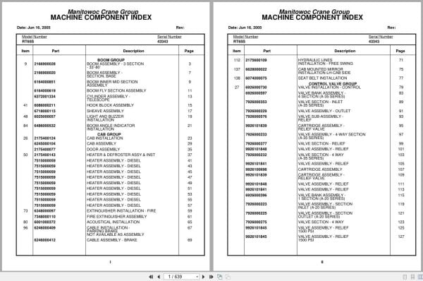
Boom Assembly – 3 Section – 33’-80’
Boom Assembly – Section, Base
Boom Inner Mid Section Assembly
Boom Fly Section Assembly
Cylinder Assembly – Telescope
Hook Block Assembly
Sheave Assembly
Light And Buzzer Installation
Boom Angle Indicator Installation
Cab Installation
Cab Assembly
Door Assembly
Heater & Defroster Assy.& Inst
Heater Assembly – Diesel
Extinguisher Installation – Fire
Fire Extinguisher Assembly
Acoustical Installation
Cable Installation – Parking Brake
Cable Assembly – Brake
Hydraulic Lines Installation – Free Swing
Cab Mounted Mirror Installation -Lh-Cab Side
Seat Belt Installation
Valve Installation – Control
Valve Bank Assembly – 4 Section (A-35 Series)
Valve Section – Inlet (A-35 Series)
Valve Assembly – Outlet
Valve Sub- Assembly – Relief
Cartridge Assembly – Relief Valve
Valve Assembly – 4-Way Section (A-35 Series)
Valve Section – Relief
Valve Assembly – Relief
Valve Section – 4 Way (A-35 Series)
Cartridge Assembly
Valve Bank Assembly – 1 Section (A-20 Series)
Valve Assembly – Section Inlet (A-20 Series)
Valve Assembly – Section Outlet (A-20 Series)
Valve Section – 4 Way
Valve Assembly – Relief 1500 Psi
Valve Bank Assembly – 3 Section (A-20 Series)
Valve Assembly – Relief 2500 Psi
Valve Bank Assembly – 1 Section (A-35 Series)
Hydraulic Lines Installation – Swing
Hydraulic Lines Installation – Lift
Hydraulic Lines Installation – Telescope Mid
Hydraulic Lines Installation – Telescope Fly
Hydraulic Lines Installation – Main Hoist
Hoist Installation – Main
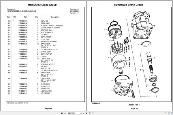
Hoist Assembly – Model Ho30b-16
Motor Assembly , Hydraulic
Valve Assembly – Selector
Valve Assembly – Motor Control
Follower Installation – Cable
Rotation Indicator Installation
Driver Assembly Driver Assembly
Indicator Assembly
Transmitter Assembly
Support Installation – Tube
Swivel Assembly And Installation
Swivel Assembly – Hydraulic
Swivel Assembly – 10 Port
Ring Assembly – Slip 32 Conductor
Manifold Installation – Hydraulic
Lift Cylinder Installation
Cylinder Assembly – Lift
Drive Install – Turntable
Swing Box And Brake Assembly
Box Assembly – Swing
Motor Assembly – Orbit
Brake Assembly – Mechanical
Brake Assembly – Disc
Counterweight Install.Mod.#30a
Reel Installation – Hose
Hose Reel Assembly – Right Hand
Tank Install – Emergency Air
Elevation And Swing Warning Installation
Switch Assembly – Limit
Turntable Lock Pin Installation Installation
Pivot Shaft Installation – Boom
Bearing Bolt Installation
Storage Installation – Removable Windshield
Engine Installation – Gmc6v-53n
Hood Assembly – Engine
Filter Assembly – Oil
Torque Converter Assembly
Fitting Assy
Pump Assembly – Steer
Transmission Installation
Transmission Assembly
Valve Assembly – Transmission Shift Control
Transmission Assembly Valve Assembly –
Driveline Installation
Driveline (Front Axle)
Driveline Assembly
Driveline (Rear Axle)
Driveline (Transmission)
Shifter Installation – Hi-Lo
Cylinder Assembly – Air
Valve Assembly – 3 Way Solenoid
Transmission And Converter Lines Installation
Hydraulic Shift Converter Line Installation
Axle Installation – Front
Cylinder Assembly – Steer
Rear Axle Installation
Cylinder Assembly -Lockout
Axle Assembly – Rear
Axle Assembly – Drive Steer
Axle Assembly – Drive Steer Housing Assembly
Axle Assembly – Drive Steer Differential And Carrier
Axle Assembly – Drive Steer Hub And Shaft Group
Axle Assembly – Drive Steer Brake Assembly
Axle Assembly – Drive Steer Wedge Assembly
Axle Assembly – Drive Steer Brake Chamber Assembly
Axle Assembly – 3’’ Steer
Tire And Wheel Assembly
Valve Installation – Rear Axle Lockout
Valve Installation – Front Steer
Rear Axle Lockout Override Installation
Valve Assembly – Solenoid
Indicator Installation – Rear Steer
Hydraulic Lines Installation – Front Steer
Hydraulic Lines Installation – Rear Steer
Hydraulic Lines Installation – Axle Lockout With Override
Lug Nut And Washer Installation
Outrigger And Valve- Installation
Cylinder Assembly – Stabilizer
Cylinder Assembly – Outrigger
Hydraulic Lines Installation – Outrigger
Valve, Pressure Relief
Float Assembly – Outrigger
Hydraulic Reservoir And Deck Installation
Fuel Tank, Battery Box,And Cover Installation
Air Tanks, Valves, And Cover Installation
Valve Assembly – Quick Release
Valve Assembly – Relay
Light And Turn Signal Installation
Fenders And Storage Well Assembly And Installation
Hydraulic Lines Installation – Supply, Pressure And Return
Decal Installation – Rt65s/75s
Cover And Handle Assembly – Hydraulic Pump Disconnect
Alarm Installation – Back-Up
Air Brake And Throttle Line Installation
Valve Assembly – Check
Air Brake & Throttle Lines Ins
Rear View Mirror Installation
Pintle Hook Installation
Pintle Hook Assembly
Wiring Harness Installation – Carrier
Air Dryer Installation
Dryer Assembly – Air
Air Brake And Throttle Lines
Wiring Diagram

REALEASE :
REALEASE :

REALEASE :
REALEASE :

REALEASE :
REALEASE :

REALEASE :
REALEASE :

REALEASE :
REALEASE :

REALEASE :
REALEASE :

REALEASE :
REALEASE :

REALEASE :
REALEASE :
 Automotive - Heavy Equipment - Truck & Bus - Forklift - Crane