
16 ITEMSVIEW CART


Total: 2,472.00
Expert Support
Full Speed
100% Working
20 USD
Contents:
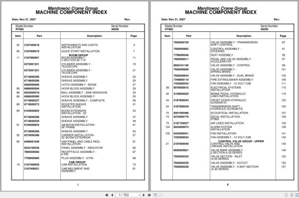
Instruments And Lights Installation
Quick Start Installation
Boom Assembly – 4 Section 36’-114’
Cylinder Assembly – Telescope
Sheave Assembly
Latch Assembly – Boom
Hook Block Assembly
Ball Assembly – 300# Headache
Sheave Assembly – Complete
Rooster Sheave Installation
Boom Extension Installation – 32’
Jib Boom Installation – 28’ Frame
Carrier Installation – 32’ Boom Extension
Hap Panel And Cable Reel Installation
Panel Assembly – Indicator
Receptacle Assembly – 6 Pin
Plug Assembly – 6 Pin
Cab Installation
Cab Weldment And Assembly
Valve Assembly – Transmission Shift Control
Control Assembly – Steering
Seat Assembly
Pedal And Valve Assembly – Accelerator
Valve Assembly – Control
Valve Assembly – Spring Brake
Valve Assembly – Dual Brake
Fire Extinguisher Assembly
Fan Assembly – 12 Volt Cab
Electrical Systems Installation
Brake Pedal Hydraulic Lines Installation
Front Steer Hydraulic Schematic
Transmission Shift – Hydraulic Schematic
Acoustical Installation
Decal Installation – Rt865
Air Lines Installation
Alarm System Installation
Fan Installation
Control Valve And Linkage Installation
Valve Bank Assembly – 2 Section A-35 Series
Valve Section – Inlet (A-35 Series)
Valve Assembly – Outlet
Valve Assembly – 4-Way Section (A-35 Series)
Cartridge Assembly
Valve Bank Assembly – 3 Section A-35 Series
Valve Section – Relief
Valve Assembly – Relief
Valve Section – 4 Way
Relief Valve
Valve Bank Assembly – 1 Section A-20 Series
Valve Assembly – Section Inlet (A-20 Series)
Valve Section – Outlet
Valve Bank Assembly – 4 Section A-35 Series
Valve Sub- Assembly – Relief
Cartridge Assembly – Relief Valve
Free Swing – Hydraulic Schematic
Hydraulic Lines Installation – Lift
Hydraulic Lines Installation – Inner Mid Telescope
Hydraulic Lines Installation – Outer Mid
Panel Installation – Hydraulic Test
Hoist Installation
Hoist Assembly – Model Ho30a-26
Motor Assembly , Hydraulic
Valve Assembly – Selector
Valve Assembly – Motor Control
Cable Follower And Idler Assembly
Hoist Installation – Auxiliary
Hoist Assembly – Model Ho15b-16
Gear Reduction Assembly
Motor Assembly – Hydraulic
Idler Drum Assembly
Roller Assembly – Cable
Cable Follower Installation
Cable Follower Assembly – Hoist
Cable Follower
Hydraulic Lines Installation – Main And Auxiliary Hoist
Rotation Indicator Installation – Model 30
Driver Assembly Driver Assembly
Indicator Assembly
Transmitter Assembly
Rotation Indicator Installation – Model 15
Turntable Drive Installation
Swing Box And Brake Assembly
Motor Assembly – Orbit
Brake Assembly
Swivel Installation – Electric/Hydraulic
Swivel Assembly – Hydraulic
Swivel Assembly – Air/Hydraulic
Ring Assembly – Slip 36 Conductor
Lock Installation – Swing
Cylinder Installation – Lift
Cylinder Assembly – Lift
Valve Assembly – Overcenter
Counterweight Installation
Reel Installation – Hose
Reel Assembly – Hose
Elevation And Swing Warning Installation
Switch Assembly – Limit
Valve Installation – Pressure Reducing
Engine Installation – Cat – 3306t
Torque Converter Assembly
Torque Converter Assembly Converter Group
Torque Converter Assembly Pressure Regulating Valve
Torque Converter Assembly Disconnect Assembly – Pump
Pump Assembly – Steering
Pump Assembly
Cylinder Assembly – Throttle
Converter Oil Filter Installation
Filter Assembly – Oil
Hood Installation – Engine
Pump Disconnect Controls Installation
Transmission Installation
Transmission Assembly
Transmission Assembly Main Housing And Output Shaft
Transmission Assembly Clutch And Gear Parts – Main
Transmission Assembly Reverse And Third, Forward
Transmission Assembly Low Clutch Group
Transmission Assembly Disconnect Assembly
Valve Assembly Transmission
Cylinder Assembly – Air Lockout
Driveline Installation
Driveline Assembly
Transmission And Torque Converter Converter
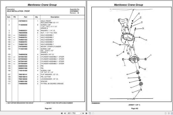
Axle Installation – Front
Axle Assembly
Axle Assembly Housing Assembly
Axle Assembly Differential Carrier Assembly
Axle Assembly Hub And Shaft Group
Axle Assembly Brake Assembly
Axle Assembly Fail Safe Brake Chamber
Cylinder Assembly – Steer
Hydraulic Lines Installation – Front Steer
Rear Steer Hydraulic Schematic
Axle Lockout Hydraulic Schematic
Valve Installation – Relief
Rear Axle Lockout Valve Assembly And Installation
Valve Assembly – Lockout
Light Installation – Red Indicator
Tire And Wheel Assembly
Tire Inflation Kit Installation
Outrigger Beam Installation
Cylinder Assembly – Stabilizer
Cylinder Assembly – Extension
Reservoir Installation – Hydraulic
Cover Installation – Hydraulic Tank
Tank Installation – Fuel
Tank Assembly – Fuel 100 Gallon
Tool Box And Ladder Installation
Fenders And Battery Box Installation
Battery Installation
Lights,Turn Signals And Back-Up Alarm Installation
Electrical Systems Installation -Carrier
Hydraulic Lines Installation – Supply, Pressure And Return
Valve Assembly – Sequence
Rear View Mirror Installation
Air Lines Installation Carrier
Dryer Assembly – Air
Valve, Relay
Emergency Steer Pump And Harness Installation
Pump And Motor Assembly
Pintle Hook Installation
Hook Assembly – Pintle
Hydraulic Lines Installation – Outrigger

REALEASE :
REALEASE :

REALEASE :
REALEASE :

REALEASE :
REALEASE :

REALEASE :
REALEASE :

REALEASE :
REALEASE :

REALEASE :
REALEASE :

REALEASE :
REALEASE :

REALEASE :
REALEASE :
 Automotive - Heavy Equipment - Truck & Bus - Forklift - Crane