")
Expert Support
Full Speed
100% Working
Hako Sweeper Citymaster Citytrac Citycleaner Service-Booklet 23843 2009
10 USD
- Description
Description
Hako Sweeper Citymaster Citytrac Citycleaner Service-Booklet 23843 2009
Size: 7.84 MB
Format: PDF
Language: English
Brand: Hako
Type of Machine: Sweeper
Type of Manual: Electrical Installations, Service-Booklet,
Training, Troubleshooting, Adjustments, Components/Suppliers
Model: Hako Sweeper
Hako – Citytrac 4200 CT4200DA (8010.11 ; 8010.12)
Hako – Citymaster 1200 CM1200 (1433.11 ; 1433.12)
Hako – Citycleaner (1433.52)
Engine: Yanmar 4TNV88MHW Engine
Part Number: 23843
Publication Date: 2009
Number of Pages: 112 Pages
List Of Files:
Citymaster Citytrac Citycleaner Electrical Installations 2009.pdf
Citymaster Citytrac Citycleaner Service-Booklet 23843 2009.pdf
1.0 Product Description
1.1 Product Description
1.2 Short Operator Manual
2.0 Technical Data
2.1 Technical Data
2.2 Overview Service
3.0 Assembly And Mechanical Design
3.1 Articulated 4-Wheel Chassis
3.1.1 Articulated Steering
3.1.2 Hydraulic Motor
3.2 Accelerator
3.3 Engine Hand Throttle
4.0 Engine
4.1 Engine Identification System
4.2 Technical Data
4.3 Overview Of Components
4.4 Crankshaft Housing Ventilation
4.5 Valve Clearance Adjustment
4.6 Changing The Injection Pump
4.7 Engine Shutdown Solenoid
5.0 Hydraulic Installations
5.1 Safety Regulations
5.2 Hydraulic Pumps
5.2.1 Overview Of Pump Locations
5.2.2 Variable Displacement Pump
5.2.3 Technical Data
5.2.4 Hydraulic Pump Description
5.2.5 Flush Valve
5.2.6 Gear Pump, Zp1
5.2.7 Gear Pump, Zp2
5.3 Traction Drive
5.3.1 System Diagram
5.3.2 Differential Lock Valve
5.3.3 Switching Valve, Working/Transport Mode
5.4 Work Hydraulics
5.4.1.1 Valve Manifold, Old
5.4.1.2 Valve Manifold, New
5.4.1.3 Torque, Valve Manifold
5.4.1.4 Measure Values Solenoid Valves
5.4.2.1 Valve Manifold, System Diagram, Old
5.4.2.2 Valve Manifold, System Diagram, New
5.4.3 Function Description, Valve Manifold
5.4.4 Proportional Throttle Cartridge
5.4.5 Functions, System Diagram
5.4.6 Proportional Valve Control Unit
5.4.7 Hydraulic Connections For Front Attachment Devices
5.4.8 Rear Connections
5.5 Citycleaner Hydraulics
6.0 Electrical Installations
6.1 Safety Information
6.2 Basic Principles
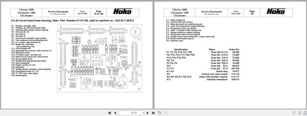
6.3 Fuse Box, Cab
6.4 Fuse Box, Trailer
6.5 Overview Of Components
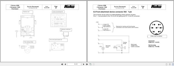
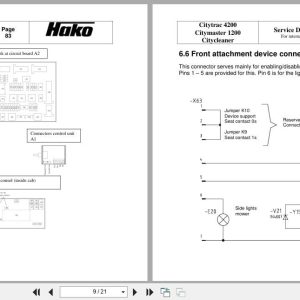
6.6 Front Attachment Device Connector
6.7 Rear Attachment Device Connector
6.8 Rear Device Connector Assignment
6.9 Switching Functions
6.10 Controller Water Regulation
6.11 Relay Surface Pressure
7.0 Options
7.1 Multipurpose Packet
7.1.1 Path-Dependent Spreading
7.1.1.1 Electrical Circuit
7.1.1.2 Control Unit
7.1.2 Rear Connections
7.2 Grass And Leaf Collector
7.3 Working Time Counters / Mileometer
7.4 High Pressure Cleaner
Related Products
-
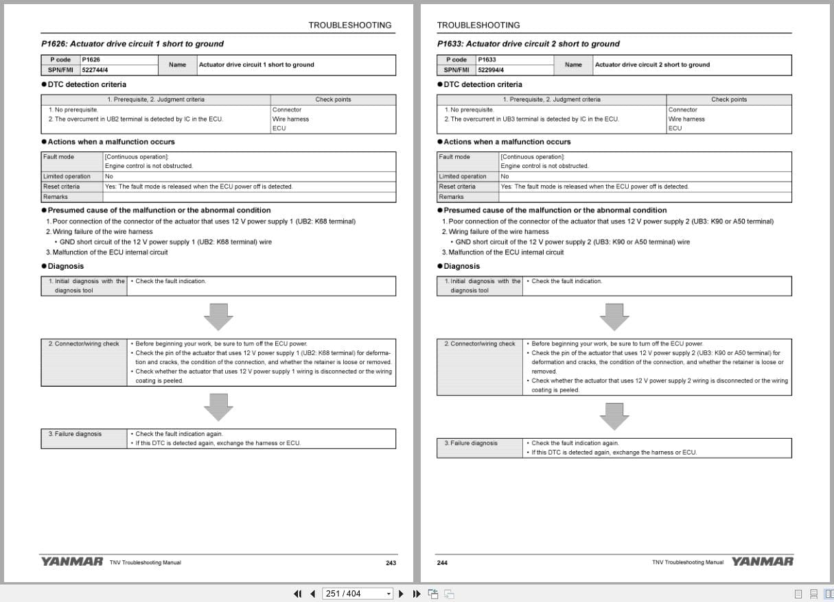
Yanmar Engine 3TNV88C To 4TNV98CT Troubleshooting Manual 0DTN4-G00200 2015
10 USD -
Hako EPC Spare Parts List PDF 8.59GB
Original price was: 200.110Current price is: 110. USD -
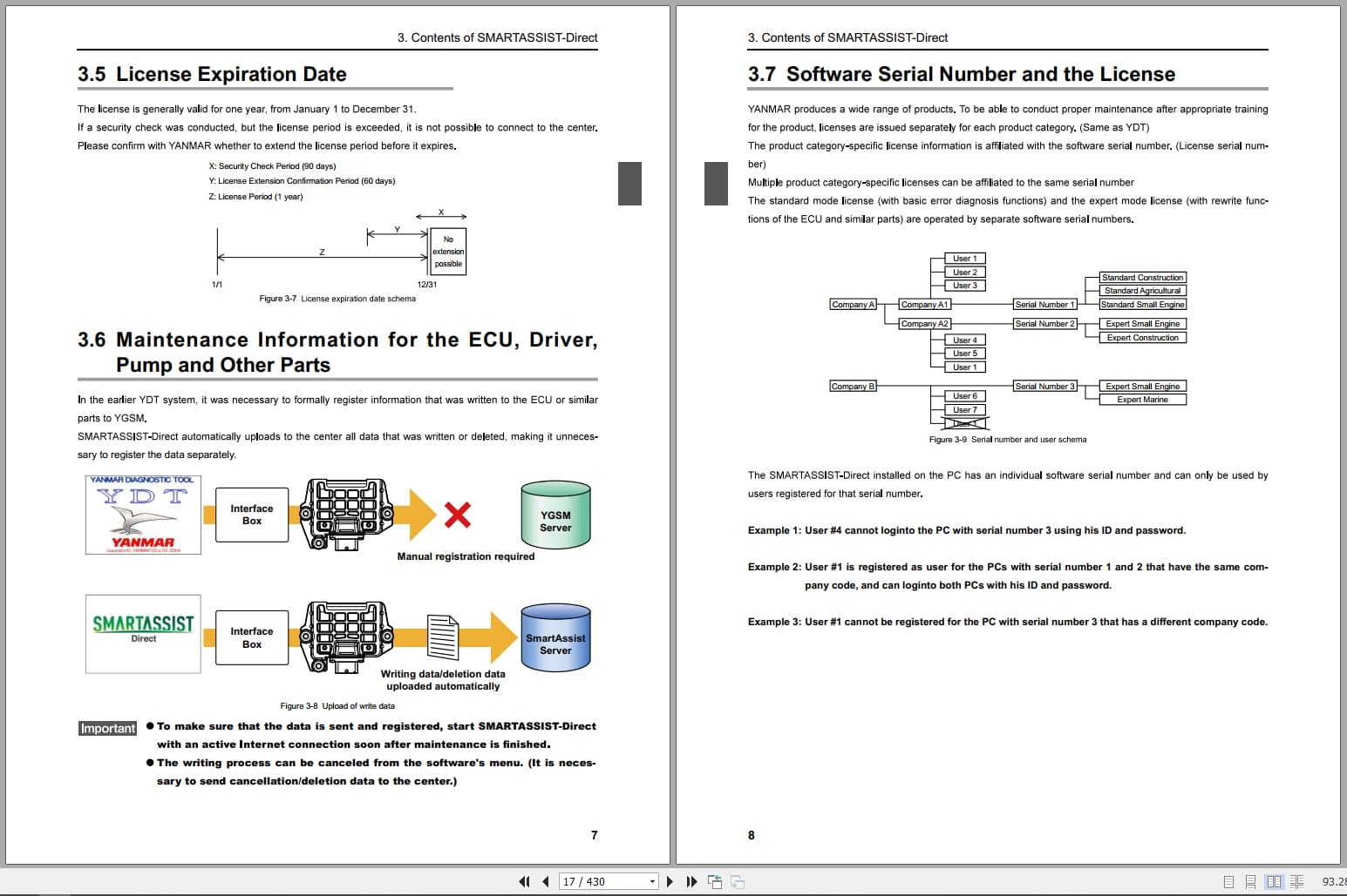
Yanmar Engine SMARTASSIST-Direct Operation Manual 0AYSA-EN0018 2018
10 USD -
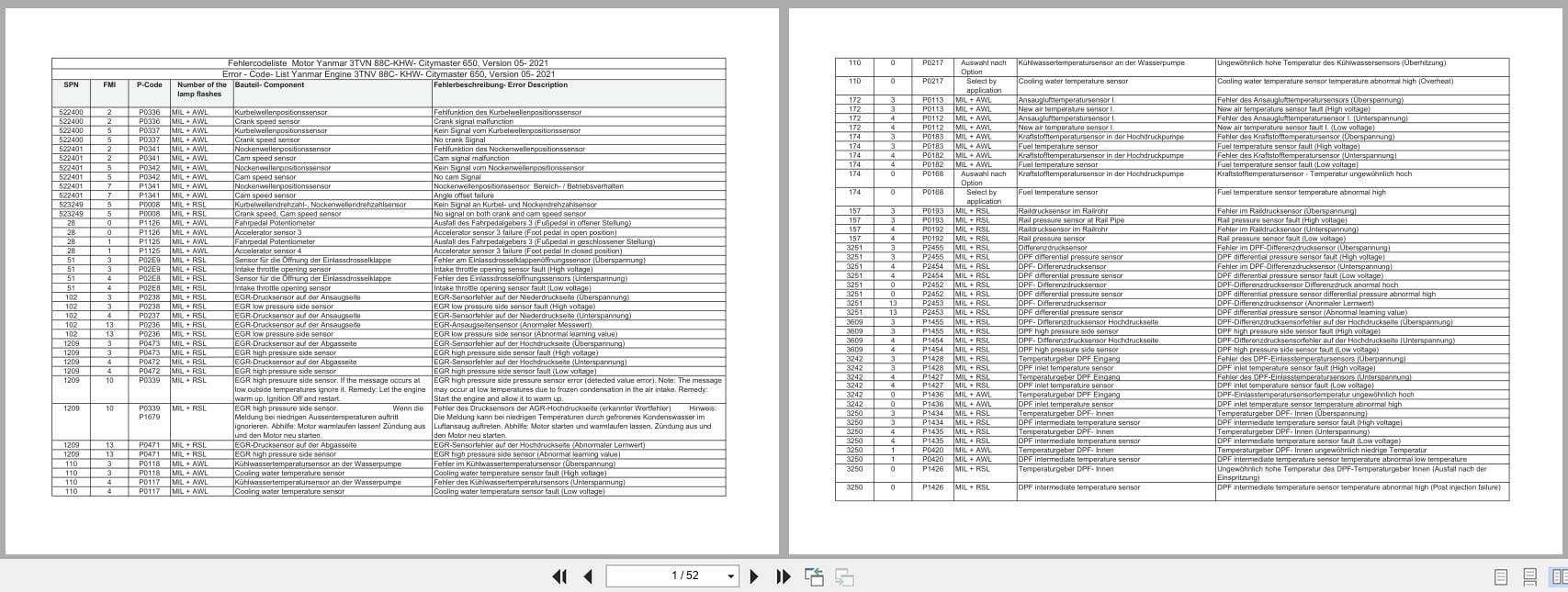
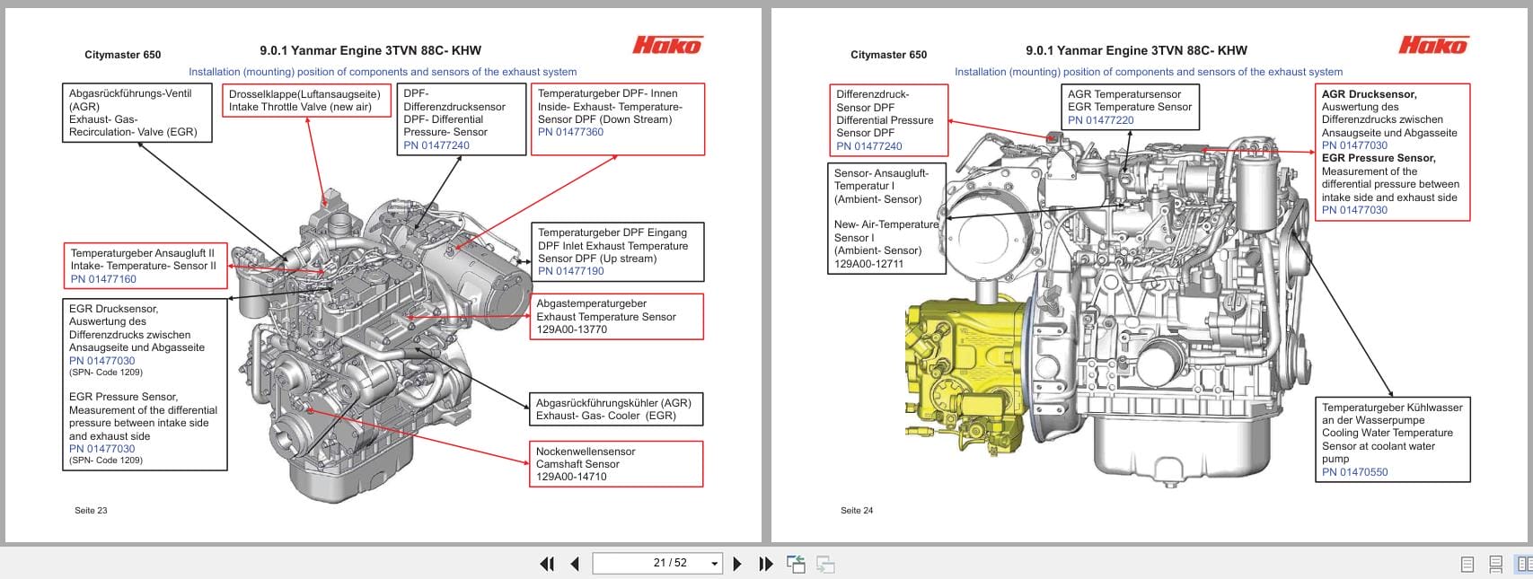
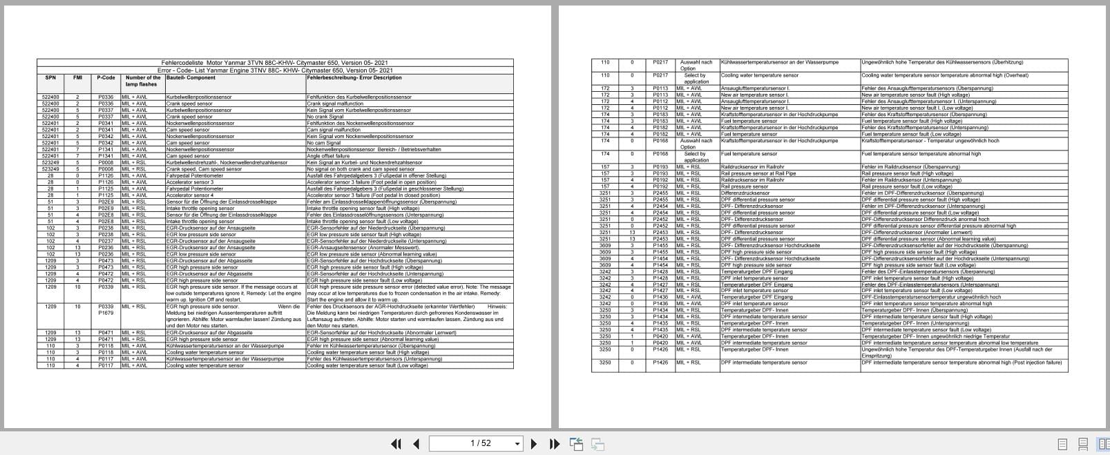
Yanmar Engine 3TNV88C-KHW Error Diagnostic Trouble Codes Wiring Diagram
10 USD -
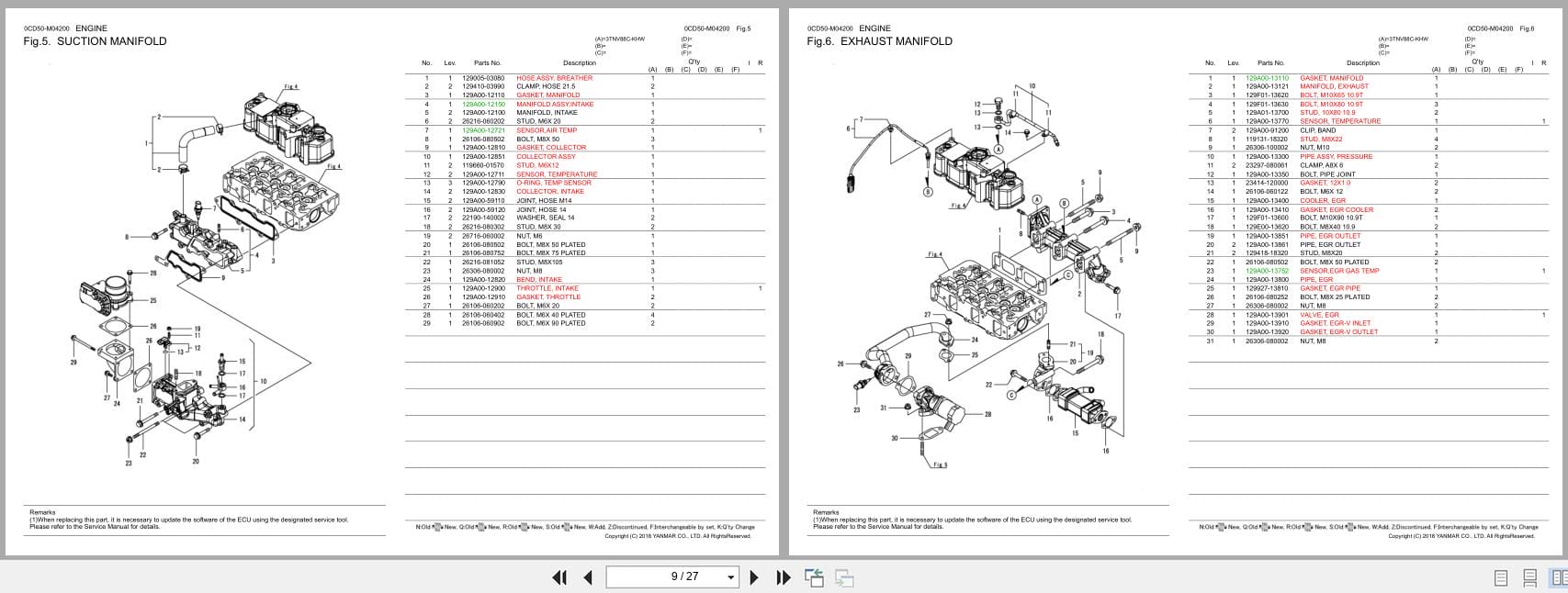
Yanmar Engine 3TNV88C-KHW Parts Catalog 0CD50-M04200EN 2018
10 USD -
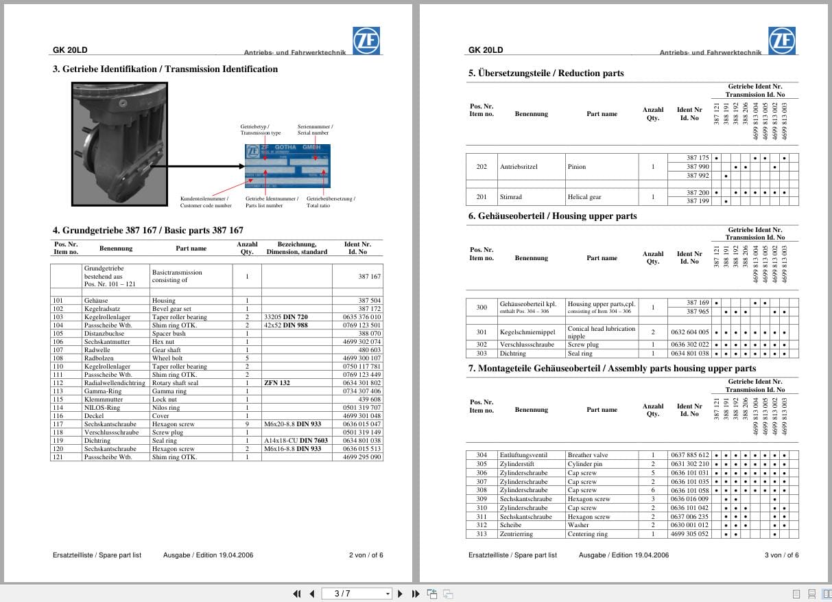
ZF Transmission GK20LD Spare Parts List
10 USD -
Yanmar Engine 3TNV88C-KHW Error Code Electrical Schematic
10 USD -
Hako Spare Parts List Machine Collection 456 MB Operating Manual
Original price was: 100.50Current price is: 50. USD