
7 ITEMSVIEW CART


Total: 710.00

Expert Support
Full Speed
100% Working
10 USD
Contents:
1 Information
2 General Information
2.1 Settings
2.1.1 Control Panel
2.1.2 Machine Control Unit
2.2 Brief Description
2.2.1 Switching Off Suction / Waste Water Tank Full
2.2.2 Solution Tank Display
2.2.3 Machine Home Position
2.2.4 Seat Contact Switch (3.6.6.4.)
2.3 Diagnostics And Communications
2.3.1 Prerequisites
2.3.2 Diagnostic Software On The Diagnostic Computer
2.3.3 Connecting To The Diagnostic PC
2.3.4 Connection Scheme With The Diagnostic PC
2.3.5 Flashing The Software
2.3.6 Flashing The SD Card
2.4 Configuration Menu
2.4.1 Entering The Configuration Menu
2.4.2 Time And Date Setting Menu
2.4.3 Configuration Setting Menu
2.4.4 Settings, That Can Be Carried Out Without Code
2.4.5 Settings, That Can Only Be Carried Out With Code
2.4.6 Resetting The Last Error And Deleting The Error Memory
2.4.7 Deleting The Last Error On The Display Panel
2.4.8 Deleting Error Entries
3 Technical Data
4 Maintenance Intervals
4.1 Hako System Maintenance (Customer)
4.2 Hako System Maintenance I
4.3 Hako System Maintenance II
4.4 Hako System Maintenance S
5 Cleaning Programmes (FPV)
5.1 Cleaning Programmes (SOW)
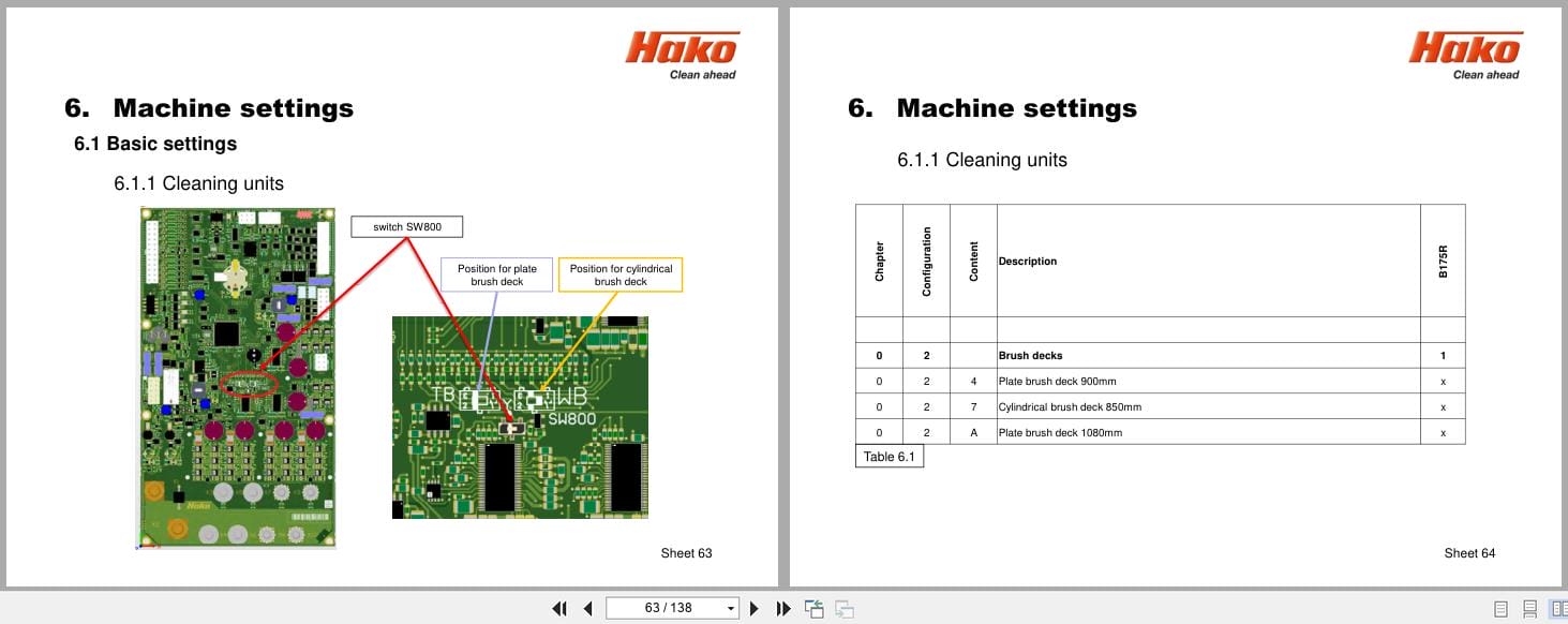
6 Machine Settings
6.1 Basic Settings
6.1.1 Cleaning Units
6.1.2 Battery And Charger Settings
6.1.3 Battery Setting (LDS)
6.1.4 Charger
6.1.5 Charger Characteristic Curves
6.1.6 Charging Data Table Of The Integrated Charger
6.1.7 All-Wheel Drive Variant – X-Ac
6.1.8 SD Storage Medium In Control Panel
6.1.9 Logo On The Starting Screen
6.2 Customer-Specific Settings (PPV)
7 Mechanical Components
7.1 Squeegee
7.2 Rotating Brush Heads
7.3 Roller Brush Heads
7.4 Lifting Element Brush Head
7.4.1 Potentiometer In The Lifting Element For The Brush Head
8 Water Pump
8.1 Water Supply – Components On The Water Plate
8.2 Water Quantities
8.3 Water Pump Standstill Detection
8.4 Suction-And Speay Tool; Spray Nozzle
9 Drive System
9.1 DMC Drive Control Unit (Front)
9.1.1 Connection Description – Drive Control Unit (Front)
9.1.2 Service Codes – Drive Control Unit (Front)
9.1.3 Brake – Manual Release Of The Brake (Front)
9.1.4 Brake – Testing The Brake Function
9.2 DMC Drive Control Unit (Rear)
9.2.1 Connection Description – Drive Control Unit (Rear)
9.2.2 Service Codes – Drive Control Unit (Rear)
9.2.3 Brake At The Rear Axle
9.2.4 Steering Angle Sensor
10 Service Messages
10.1 Meaning Of Different Switch On Displays
10.2 Service Alarm Clock 3.3.1.1
11 Battery Charger
11.1 Operating Manual
11.2 Programming The Charger
12 Options
13 Electrical Components
13.1 Machine Control Unit A01
13.2 Dashboard A02
14 Notes
REALEASE :
REALEASE :
REALEASE :
REALEASE :

REALEASE :
REALEASE :

REALEASE :
REALEASE :

REALEASE :
REALEASE :
REALEASE :
REALEASE :

REALEASE :
REALEASE :
REALEASE :
REALEASE :
 Automotive - Heavy Equipment - Truck & Bus - Forklift - Crane