
2 ITEMSVIEW CART


Total: 45.00
Expert Support
Full Speed
100% Working
50 USD
Contents:
1. Revision Summary Table
2. Foreword:
3. Vehicle Architectures:
3.1. Multiplexing Architecture:
3.2. Vehicle Multiplex Architecture
3.3. Vehicle Power Distribution Architecture:
4. Body Control Module (BCM)
4.1. Body Control Module Gen IV:
4.2. Body Control Module “Real-time Clock†Internal Power Source:
4.3. Body Control Module Gen IV Connector Composite:
4.4. Body Controller J1 Connector 1603 I/O & Part Number Detail:
4.5. Body Controller J2 Connector 1604 I/O & Part Number Detail:
4.6. Body Controller J3 Connector 1600 I/O & Part Number Detail:
4.7. Body Controller J4 Connector 1601 I/O & Part Number Detail:
4.8. Body Controller J5 Connector 1602 I/O & Part Number Detail:
4.9. Body Controller J6 Connector 1605 I/O & Part Number Detail:
4.10. Body Controller J7 Connector 1606 I/O & Part Number Detail:
5. Multiplex Switch-Packs (Center Panel Mounted)
5.1. Multiplex Switch-Pack Housing:
5.2. Multiplex Switch-Pack Cover
5.3. Multiplex Switch-Pack Storage Bin:
5.4. Multiplex Switch-Pack Actuators, Blanks (plugs) and Indicators:
5.5. Multiplex Switch-Pack Warning Lights:
5.6. Switch Label Applique Sheet #1 (Utility/Wrecker):
5.7. Switch Label Applique Sheet #2 (Fire):
5.8. Switch Label Applique Sheet #3 (Limo/Bus/Propane):
5.9. Switch Label Applique Sheet #4 (Airport Refueler/Concrete Mixer):
5.10. Switch Label Applique Sheet #5 (Plow/Dump):
5.11. Switch Label Applique Sheet #6 (Tanker)
5.12. Switch Label Applique Sheet #7 (Ambulance/Fire):
5.13. Switch Label Applique Sheet #8 (Adv Fire/Ambulance):
5.14. Switch Label Applique Sheet #9 (On/Off/Blank):
5.15. Switch Label Applique Sheet #10 (Miscellaneous):
6. Customized Steering Wheel Switches
7. Lighting Control Module:
7.1. Lighting Control Module Housing:
7.2. Lighting Control Module and Associated Parts:
8. Remote Power Modules:
8.1. Remote Power Module Composite View
8.2. Remote Power Module CAN Pass-through Connector
8.3. Body Equipment Power Output Connector
8.4. Body Equipment Signal Input Connector
8.5. Remote Power Module Address Jumper Locations
8.6. Remote Power Module Power Connections
9. Instrument Panel
10. Air Conditioning
11. 12 Volt System
11.1. 12-VOLT BATTERY CHARGING
11.2. 08RMH: BATTERY DISCONNECT SWITCH Cole-Hersee 75920-06} 300 Amp, Disconnects Charging
Circuits, Locks with Padlock, Battery Box Mounted.
12. Body Builder Wiring, for Stop/Turn/Tail Lights/ Through Power:
12.1. 08HAA: BODY BUILDER WIRING To EOF, With Stop, Tail, Turn, and Marker Lights Circuits, Ignition
(IGN)-Controlled Auxiliary Feed and Ground (GND), Less Trailer Socket.
13. CB and 2-Way Radio Accommodation Packages
13.1. 08RNC: CB RADIO Accommodation Package, Header Mounted, Feeds from Accessory Side of Ignition
Switch, Includes Power Source, Two Antennas and Antenna Bases with Wiring on Both Side Mirror
14. Fog Light Package
14.1. 08XJH: FOG LIGHTS (2) Clear Lens, LED, Rectangular, with White Light Source
15. Gauges and Fault Code Display
15.1. 16HKA IP CLUSTER DISPLAY Omit Display of Diagnostic Trouble Codes in Instrument Cluster and
Disable Blink Codes, Requires Service Tool to Retrieve and View Fault Code
16. In Cab Battery Feed and USB Power Source
16.1. 08XPK: POWER SOURCE, ADDITIONAL Auxiliary Power Outlet (APO) with USB-A Port and USB-C
Port, Located in the Instrument Panel.
16.2. 08XPL: POWER SOURCE, ADDITIONAL Auxiliary Power Outlet (APO) with Two USB-A Ports and Two
USB-C Ports, Located in the Instrument Panel.
16.3. 08XPN: USB PORT One USB-A Port and one USB-C Port, Located in the Instrument Panel.
16.4. 08XPP: USB PORT Two USB-A Ports and Two USB-C Ports, Located in the Instrument Panel
17. Liftgate Accommodation Package
17.1. 08VBA: POWER SOURCE, SPECIAL for Customer Installed Lift Gate; 200 Amp Max, Includes 00ga.
Power Cable to End of Frame, Optional Power (PDM) for Power Source, Latched Switch on Instrument
Panel, with a Time Out Feature, Battery Discharge Protection, Controlling a Mag Switch Which
Provides Power.
18. Power Window, Locks, Remote Keyless Entry
18.1. 16VDZ: KEYLESS ENTRY SYSTEM REMOTE with Panic and Auxiliary Work Light Function, Includes
Two Key Fobs (Transmitters).
18.2. 16WJU: WINDOW, POWER (2-Door) and Power Locks, Left and Right Doors.
18.3. 16WKZ: KEYLESS ENTRY SYSTEM REMOTE with Panic and Auxiliary Buttons, Includes One Key Fob
(Transmitter)
19. Productivity Features
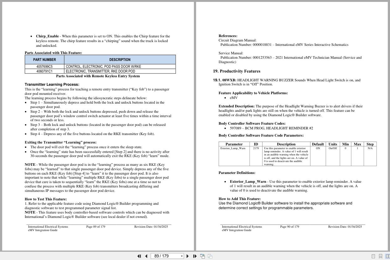
19.1. 08WXB: HEADLIGHT WARNING BUZZER Sounds When Head Light Switch is on, and Ignition Switch is
in “Off†Position.
19.2. 08WXD: ALARM, PARKING BRAKE Electric Horn Sounds in Repetitive Manner when Vehicle Park
Brake is “NOT†Set, With Ignition (IGN) “OFF†and any Door Open.
19.3. 16HCH: SEATBELT WARNING LIGHT IND. Mounted in Dash, Will Flash when Park Brake is Disengaged
and Driver Seatbelt Unfastened, Audible Alarm to Remind Driver to Fasten Seatbelt
20. Standard electrical Offerings
20.1. 08WRB: HEADLIGHTS ON W/WIPERS Headlights Will Automatically Turn on if Windshield Wipers are
turned on. There are two functions, Lights on With Wipers (LOWW) and Day Time Running Lights
(DTRL), available with this sales code.
21. Work light Outside Cab Features
21.1. 08WMA: SWITCH, TOGGLE, FOR WORK LIGHT Lighted; on Instrument Panel and Wiring Effects for
Customer Furnished Back of Cab Light
21.2. 08WTT: SWITCH, TOGGLE, FOR WORK LIGHT Lighted; on Instrument Panel and Wiring Effects for
Customer Furnished End of Frame Light
22. Body Builder Integration Harnesses
22.1. 08XMB: WIRING (1)TMC RP1226 BEHIND CTR CONSOLE CONNECTOR, DASH, CENTER PANEL
Cab Wiring for TMC RP1226 Vehicle Accessory Connector; Includes 14-pin Connector with Switched
Power, Battery Power, Ignition Power, Ground & Body 250K Datalink, Connector Located Behind
Instrument Panel Center Console
22.2. 08XMZ: WIRING (2)TMC RP1226 BEHIND CTR CONSOLECONNECTOR, DASH, CENTER PANEL
Cab Wiring for (2) TMC RP1226 Vehicle Accessory Connectors; Includes (2) 14-pin Connectors with
Switched Power, Battery Power, Ignition Power, Ground & Body 250K Datalink, Connector Located
Behind Instrument Panel Center Console
22.3. 08XNA, CENTER PANEL Cab Wiring for (3) TMC RP1226 Vehicle Accessory Connectors; Includes (3) 14-
pin Connectors with Switched Power, Battery Power, Ignition Power, Ground & Body 250K Datalink,
Connector Located Behind Instrument Panel Center Console
23. Power Features using Remote Power Modules
23.1. 60AAG: BDY INTG, REMOTE POWER MODULE Mounted Inside Cab Behind Driver Seat, Up to 6
Outputs & 6 Inputs, Max 20 amp per Channel, Max 80 amp Total; Includes 1 Switch Pack with Latched
Switches
23.2. 60AAH: BDY INTG, REMOTE POWER MODULE (2) Mounted Inside Cab Behind Driver Seat, Up to 6
Outputs & 6 Inputs Each, Max 20 amp per Channel, Max 80 amp Total; Includes 2 Switch Packs with
Latched Switches.
23.3. 60AAJ: DY INTG, REMOTE POWER MODULE (3) Mounted Inside Cab Behind Driver Seat, Up to 6
Outputs & 6 Inputs Each, Max 20 amp per Channel, Max 80 amp Total; Includes 3 switch Packs with
Latched Switches.
23.4. 60AAP: BDY INTG, REMOTE POWER MODULE (3) Mounted Inside Cab Behind Driver Seat, Up to 6
Outputs & 6 Inputs Each, Max 20 amp per Channel, Max 80 amp Total; Includes 2 Modules with Switch
Packs Containing 6 Latched Switches, 1 Module with Hardware Only
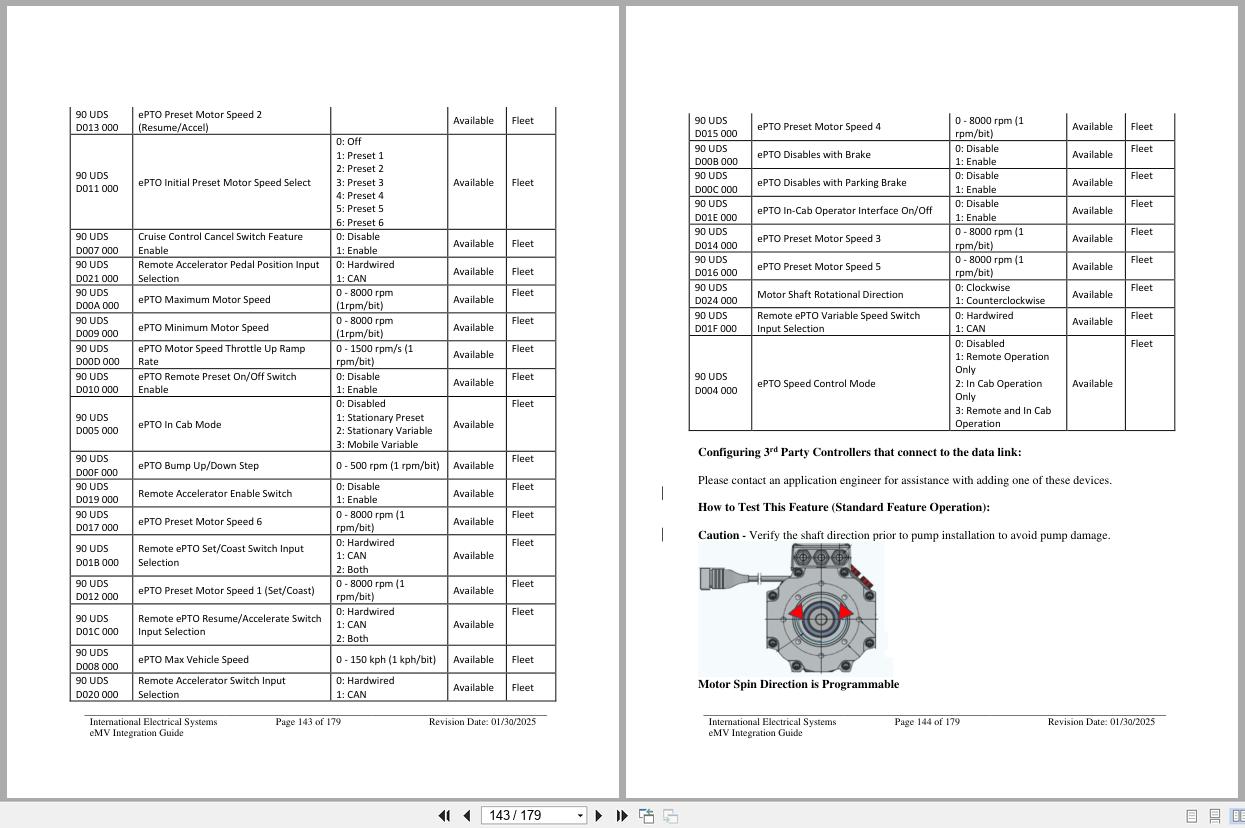
24. ePTO
08PAA: HIGH VOLTAGE POWER ACCESSORY 40kW Electronic Power Take Off, with SAE B Pump Flange, Moun
Left Side Under Cab
25. ePower
25.4. ePower LV Hardware Interface Integration
25.4.1. LV Voltage Range
25.5. ePower Electrical Interface Integration
25.5.1. LV Connector
25.5.2. LV Fuse for VBATT Connection
25.5.3. LV Fusing
25.5.4. ePower Enable
25.5.5. CAN System Diagram
25.5.6. High Voltage Range
25.5.7. HVDM Connection
25.5.8. HV Connector Plugs
25.5.9. HV Connector
25.5.10. Mating Keyed Connectors F (Plug/Mating connector for HV Harness)
25.5.11. HV Cable
The wire selection based on the plugs as defined in section 25.5.8
25.5.12. HVDM Fuse
25.5.13. HVDM Location
25.5.14. HV Fuse
25.5.15. HVIL
25.1. System Active Discharge
25.2. Internal Contactor
25.3. System After-Run Operation
26. General Electrical Section:
26.1. “Red Gel Coat†Remo val Fro m Electrical Con nection s
26.2. Connecting to 12 Volt Circuits
26.3. Recommended Circuit Protection
26.4. Color Code System for International® Truck Wiring:
26.5. Electrical Components Commonly Used by Equipment Installers:
26.6. Suppression
26.7. Welding Information
26.8. Routing Guidelines
26.9. Wire Splicing and Termination – Standard Terminals and Splices:
26.10. HIGH VOLTAGE CIRCUITS (GREATER THAN 50 VOLTS) ON INTERNATIONAL TRUCKS AND
BUSES:
REALEASE :
REALEASE :

REALEASE :
14.04.2022
REALEASE :
14.04.2022
REALEASE :
REALEASE :
REALEASE :
REALEASE :
REALEASE :
REALEASE :
REALEASE :
REALEASE :

REALEASE :
REALEASE :
REALEASE :
REALEASE :
 Automotive - Heavy Equipment - Truck & Bus - Forklift - Crane