
2 ITEMSVIEW CART


Total: 470.00

Expert Support
Full Speed
100% Working
100 USD
Contents:
General Information
Safety
Recognize Safety Information
Follow Safety Instructions
Operate Only If Qualified
Wear Protective Equipment
Avoid Unauthorized Machine Modifications
Inspect Machine
Stay Clear of Moving Parts
Avoid High-Pressure Fluids
Avoid High-Pressure Oils
Beware of Exhaust Fumes
Prevent Fires
Prevent Battery Explosions
Handle Chemical Products Safely
Dispose of Waste Properly
Prepare for Emergencies
Use Steps and Handholds Correctly
Start Only From Operator′s Seat
Use and Maintain Seat Belt
Prevent Unintended Machine Movement
Avoid Work Site Hazards
Keep Riders Off Machine
Avoid Backover Accidents
Avoid Machine Tip-Over
Operating Or Traveling On Public Roads
Inspect and Maintain ROPS
Add and Operate Attachments Safely
Park And Prepare For Service Safely
Service Cooling System Safely
Remove Paint Before Welding or Heating
Make Welding Repairs Safely
Drive Metal Pins Safely
Service Tires Safely
Diagnostics
Transmission Control Unit (TCU) Diagnostic Trouble Codes
000177.00— Transmission Oil Temperature High
000177.04— Transmission Oil Temperature Short To Ground
000525.02— Program Variable REQ_GEAR Has Taken On An Invalid Value
000525.12— Request For An Undefined Shift Being Made
000723.02— Engine Speed Sensor Bias Voltage Out Of Tolerance
002000.02— ECU CAN Data Invalid
002000.09— Can Communication Lost For ECU
002033.02— FLC CAN Data Invalid
002033.09— CAN Communication Lost For FLC
002225.09— CAN Communication Lost For Six Wheel Drive
522252.00— Clutch 1 Hold Pressure Too High
522252.01— Clutch 1 Hold Pressure Too Low
522253.00— Clutch 2 Hold Pressure Too High
522253.01— Clutch 2 Hold Pressure Too Low
522254.00— Clutch 3 Hold Pressure Too High
522254.01— Clutch 3 Hold Pressure Too Low
522255.00— Clutch 4 Hold Pressure Too High
522255.01— Clutch 4 Hold Pressure Too Low
522256.00— Clutch A Hold Pressure Too High
522256.01— Clutch A Hold Pressure Too Low
522257.00— Clutch B Hold Pressure Too High
522257.01— Clutch B Hold Pressure Too Low
522258.00— Clutch C Hold Pressure Too High
522258.01— Clutch C Hold Pressure Too Low
522259.00— Clutch D Hold Pressure Too High
522259.01— Clutch D Hold Pressure Too Low
522397.04— Not In Forward Or Reverse While In Gear
522398.12— Park And Not Park Both Active
522405.05— Park Brake Pressure Low At Power-up
522413.12— Gear Bits Active In Park
522414.03— Transmission Clutch D Short To Power
522414.05— Transmission Clutch D Open/Short To Ground
522507.14— Inching Pedal During Trans Calibration
522517.31— Engine Stall Prevention Active
523655.03— Forward And Reverse Both Active
523699.31— Transmission Speed Clutch Slipping
523700.00— Clutch Protection Excessive Inching
523700.16— Clutch Protection Excessive Inching
523700.31— Transmission Direction Clutch Slipping
523708.02— Inching Switch Signal Bad
523712.31— Transmission CAL Without Park Brake Set
523717.31— Helper Clutch Pressure High
523718.31— Clutch Drum Speed Decel Excessive
523720.00— Clutch D Fill Time Too Long
523720.01— Clutch D Fill Time Too Short
523721.00— Clutch C Fill Time Too Long
523721.01— Clutch C Fill Time Too Short
523722.00— Clutch B Fill Time Too Long
523722.01— Clutch B Fill Time Too Short
523723.00— Clutch A Fill Time Too Long
523723.01— Clutch A Fill Time Too Short
523724.00— Clutch 4 Fill Time Too Long
523724.01— Clutch 4 Fill Time Too Short
523725.00— Clutch 3 Fill Time Too Long
523725.01— Clutch 3 Fill Time Too Short
523726.00— Clutch 2 Fill Time Too Long
523726.01— Clutch 2 Fill Time Too Short
523727.00— Clutch 1 Fill Time Too Long
523727.01— Clutch 1 Fill Time Too Short
523728.31— Transmission Reverse Cylinder Speed Incorrect At Calibration
523729.31— Transmission Forward Cylinder Speed Incorrect At Calibration
523730.31— No Transmission Cylinder Speed During Calibration
523731.31— Transmission Output Speed Detected At Calibration
523732.31— Engine Speed Too Low To Calibrate The Transmission
523733.31— Engine Speed Too High To Calibrate The Transmission
523734.31— Transmission Too Cold To Calibrate
523735.04— Valve Driver Supply Voltage Low
523736.14— Bad Gear Position Switch State
523738.02— Shifter Handle Problem
523738.31— Shifter Handle Problem
523739.31— Not Park And Forward/Reverse Mismatch
523740.31— Forward/Reverse Switch And Gear Mismatch
523741.31— Started In Gear
523742.31— Shifter Vsense Low
523747.14— Park and Not Park Both Passive
523750.04— Not Park Passive In Gear Or Neutral
523754.03— Not Park Active At Startup
523755.05— Park Start Input Passive At Power Up
523761.03— Transmission Clutch 4 Short To Power
523761.05— Transmission Clutch 4 Open/Short To Ground
523762.03— Transmission Clutch 3 Short To Power
523762.05— Transmission Clutch 3 Open/Short To Ground
523763.03— Transmission Clutch 2 Short To Power
523763.05— Transmission Clutch 2 Open/Short To Ground
523764.03— Transmission Clutch 1 Short To Power
523764.05— Transmission Clutch 1 Open/Short To Ground
524029.00— Inching Pedal Out Of Range High
524029.01— Inching Pedal Out Of Range Low
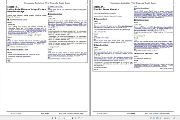
524029.12— Inching Pedal Minimum Voltage Exceeds Maximum Voltage
524194.07— Direction Sensor Mismatch
524271.03— Transmission Clutch C Short To Power
524271.05— Transmission Clutch C Open/Short To Ground
524272.03— Transmission Clutch B Short To Power
524272.05— Transmission Clutch B Open/Short To Ground
524273.03— Transmission Clutch A Short To Power
524273.05— Transmission Clutch A Open/Short To Ground
524275.31— Forward/Reverse Without Valid Gear
Engine Control Unit (ECU) Diagnostic Trouble Codes
29.03— Decel Pedal Short to Power
91.03— Accel Pedal Short to Power
91.04— Accel Pedal Open or Short
107.00— Engine Air Filter Restricted
596.31— Engine Speed Control Enable Switch Fault
600.31— Engine Speed Accel/ Decel Switch Fault
1196.31— ECU Anti Theft Locked
1321.05— Starter Relay Open Circuit
1321.06— Starter Relay High Current
1321.30— Starter Engaged for 30 Seconds
1321.31— Starter Solenoid Open Circuit
2003.09— CAN Communication Lost For TCU
2033.09— CAN Communication Lost For FLC
Advance Display Unit (ADU) Diagnostic Trouble Codes
158.03— Switched Power Voltage High
158.04— Switched Power Voltage Low
168.03— Battery Voltage High
168.04— Battery Voltage Low
442.00— Display Temperature High
442.01— Display Temperature Low
1491.11— LCD Backlight Failure
2033.09— CAN Communication Lost For FLC
3597.02— 5.0 Volt Power Supply Invalid
3598.02— 1.5 Volt Power Supply Invalid
3599.02— 3.3 Volt Power Supply Invalid
523436.14— ADU Watchdog Time Out
523438.31— Memory Error
523651.02— Memory Stack Overflow
523773.03— CAN High Voltage High
523773.04— CAN High Voltage Low
523774.03— CAN Low Voltage High
523774.04— CAN Low Voltage Low
524076.10— Information Button Stuck
524077.10— Back Key Button Stuck
524078.10— Menu Select Button Stuck
524080.10— Down Arrow Button Stuck
524082.10— Up Arrow Button Stuck
Flex Load Controller (FLC) Diagnostic Trouble Codes
96.03— Fuel Level Sender Open or Short
96.04— Fuel Level Sender Short To Ground
117.01— Service Brake Pressure Low
117.04— Service Brake Accumulator Switch Short to Ground
167.03— System Voltage Above Normal
167.04— System Voltage Below Normal
168.03— High Battery Voltage
168.04— Low Battery Voltage
628.12— Updating Software
746.05— Differential Lock Solenoid Open or Short
746.06— Differential Lock Solenoid High Current
880.05— Brake Lights Open or Short
880.06— Brake Lights High Current
977.05— Reverse Fan Solenoid Open or Short
977.06— Reverse Fan Solenoid Short to Ground
977.07— Fan Pressure Too High to Reverse
1045.04— Brake Light Switch Short to Ground
1071.03— Fan Speed Solenoid Open or Short
1071.04— Fan Speed Solenoid High Current
1550.05— AC Clutch Open Circuit
1550.06— AC Clutch Short to Ground
1638.00— Hydraulic Oil High Temperature
1638.04— Hydraulic Oil Temp Short To Ground
1713.01— Hydraulic Oil Filter Restricted
1713.03— Hydraulic Oil Filter Switch Short to Power
001762.01— Hydraulic Pressure Low
001762.03— Hydraulic Pressure Short to Power
001762.04— Hydraulic Pressure Short to Ground
2000.09— CAN Communication Lost For ECU
2003.09— CAN Communication Lost For TCU
2034.09— CAN Communication Lost For AVC
2040.09— CAN Communication Lost For ADU
2141.09— CAN Communication Lost For SSM
2160.09— CAN Communication Lost For RJ1
2161.09— CAN Communication Lost For RJ2
2162.09— CAN Communication Lost For RJ3
2163.09— CAN Communication Lost For RJ4
2165.09— CAN Communication Lost For LJ1
2166.09— CAN Communication Lost For LJ2
2167.09— CAN Communication Lost For LJ3
2168.09— CAN Communication Lost For LJ4
2213.09— CAN Communication Lost For HVC
2225.09— CAN Communication Lost For 6WD
2348.05— Hi Beam Lamps Open Circuit
2348.06— High Beam Lamps High Current
2350.05— Low Beam Lamps Open Circuit
2350.06— Low Beam Lamps High Current
2352.05— Cab Front Work Lights Open Circuit
2352.06— Cab Front Work Lights High Current
2353.05— Front Work Lights Open Circuit
2353.06— Front Work Lights High Current
2356.05— Front Cab Corner Lights Open Circuit
2356.06— Front Cab Corner Lights High Current
2360.05— Rear Work Lights Open Circuit
2360.06— Rear Work Lights High Current
2362.05— Rear Cab Corner Lights Open Circuit
2362.06— Rear Cab Corner Lights High Current
2366.05— Side Work Lights Open Circuit
2366.06— Side Work Lights High Current
2368.05— Left Turn Lights Open Circuit
2368.06— Left Turn Lights High Current
2370.05— Right Turn Lights Open Circuit
2370.06— Right Turn Lights High Current
2378.05— Marker/Tail Lights Open Circuit
2378.06— Marker/Tail Lights High Current
2386.06— Rotary Beacon Short to Ground
2874.04— High Beam Switch Short to Ground
2876.04— Turn Signal Switch Short to Ground
2927.03— Steering Angle Sensor Short to Power
2927.04— Steering Angle Sensor Short to Ground
3318.03— Blade Pitch Sensor Short to Power
3318.04— Blade Pitch Sensor Short to Ground
3319.03— Slope Sensor Short to Power
3319.04— Slope Sensor Short to Ground
3331.03— Circle Rotate Sensor Short to Power
3331.04— Circle Rotate Sensor Short to Ground
3509.04— Sensor Supply 1 Short to Ground
3510.03— Sensor Supply 2 Short to Power
3510.04— Sensor Supply Voltage 2 Short to Ground
3511.03— Sensor Supply Voltage 3 Short to Power
3511.04— Sensor Supply Voltage 3 Short to Ground
520450.03— Saddle Lock Pin Switch Short to Power
521650.00— Fan Pressure Extremely High
521650.03— Hydraulic Fan Pressure Sensor Short to Power
521650.04— Hydraulic Fan Pressure Sensor Short to Ground
521900.03— Articulation Angle Sensor Short to Power
521900.04— Articulation Angle Sensor Short to Ground
522340.05— Saddle Lock Solenoid Open Circuit
522340.06— Saddle Lock Solenoid High Current
522341.05— Heated Mirror Open Circuit
522341.06— Heated Mirror High Current
522343.06— Rear Window Defrost Relay High Current
522375.01— Transmission Oil Filter Restricted
522375.03— Transmission Oil Filter Switch Short to Power
522415.05— Front Lower Washer Pump Open Circuit
522415.06— Front Lower Washer Pump High Current
522416.05— Front Lower Wiper High-Speed Open Circuit
522416.06— Front Lower Wiper High-Speed High Current
522417.05— Front Lower Wiper Park Open Circuit
522426.05— Rear Wiper Park Open Circuit
522427.05— Front Wiper Park Open Circuit
522418.05— Front Lower Wiper Low-Speed Open Circuit
522418.06— Front Lower Wiper Low-Speed High Current
522433.05— Rear Wiper Low-Speed Open Circuit
522433.06— Rear Wiper Low-Speed High Current
522434.05— Front Wiper Low-Speed Open Circuit
522434.06— Front Wiper Low-Speed High Current
522435.05— Front Wiper High-Speed Open Circuit
522435.06— Front Wiper High-Speed High Current
522796.05— Rear Washer Pump Open Circuit
522796.06— Rear Washer Pump High Current
522797.05— Front Washer Pump Open Circuit
522797.06— Front Washer Pump High Current
523440.04— Unswitched Power Voltage Low
523688.03— Steering Angle Sensor Short To Power
523688.04— Steering Angle Sensor Short To Ground
523689.04— Differential Lock Switch Short to Ground
523901.01— Front Lower Window Switch Short to Ground
524044.01— Axle Oil Filter Restricted
524044.03— Axle Oil Filter Switch Short to Power
Hydraulic Valve Controller (HVC) Diagnostic Trouble Codes
000583.03— Mainfall Sensor Short to Power
000583.04— Mainfall Sensor Short to Ground
1503.04— Left Armrest Up Switch Short to Ground
1503.13— Left Armrest Position Undetermined
1565.04— Left Armrest Down Switch Short to Ground
1566.04— Right Armrest Down Switch Short to Ground
001899.03— Circle Side Shift A Short to Power
001899.04— Circle Side Shift A Open or Short to Ground
001900.03— Circle Side Shift B Short to Power
001900.04— Circle Side Shift B Open or Short to Ground
001911.03— Wheel Lean A Short to Power
001911.04— Wheel Lean A Open or Short to Ground
001912.03— Wheel Lean B Short to Power
001912.04— Wheel Lean B Open or Short to Ground
001923.03— Right Blade Lift A Short to Power
001923.04— Right Blade Lift A Open or Short to Ground
001924.03— Right Blade Lift B Short to Power
001924.04— Right Blade Lift B Open or Short to Ground
001935.03— Articulation A Short to Power
001935.04— Articulation A Open or Short to Ground
001936.03— Articulation B Short to Power
001936.04— Articulation B Open or Short to Ground
001947.03— Circle Rotate A Short to Power
001947.04— Circle Rotate A Open or Short to Ground
001948.03— Circle Rotate B Short to Power
001948.04— Circle Rotate B Open or Short to Ground
001959.03— Blade Side Shift A Short to Power
001959.04— Blade Side Shift A Open or Short to Ground
001960.03— Blade Side Shift B Short to Power
001960.04— Blade Side Shift B Open or Short to Ground
001971.03— Left Blade Lift A Short to Power
001971.04— Left Blade Lift A Open or Short to Ground
001972.03— Left Blade Lift B Short to Power
001972.04— Left Blade Lift B Open or Short to Ground
001983.03— Steering Left A Short to Power
001983.04— Steering Left A Open or Short to Ground
001984.03— Steering Left B Short to Power
001984.04— Steering Left B Open or Short to Ground
2000.09— CAN Communication Lost For ECU
002003.09— CAN Communication Lost For TCU
002033.09— CAN Communication Lost For FLC
002034.09— CAN Communication Lost For AVC
002160.09— CAN Communication Lost For RJ1
002161.09— CAN Communication Lost For RJ2
002162.09— CAN Communication Lost For RJ3
002163.09— CAN Communication Lost For RJ4
002165.09— CAN Communication Lost For LJ1
002166.09— CAN Communication Lost For LJ2
002167.09— CAN Communication Lost For LJ3
002168.09— CAN Communication Lost For LJ4
520752.04— Return to Straight Switch 1 Short to Ground
520753.04— Return to Straight Switch 2 Short to Ground
520754.04— Return to Straight Switch 3 Short to Ground
520755.04— Return to Straight Switch 4 Short to Ground
521485.04— Right Armrest Up Switch Short to Ground
521485.13— Right Armrest Position Undetermined
523849.13— Return to Straight Switch Mismatch
Auxiliary Valve Controller (AVC) Diagnostic Trouble Codes
001995.03— Blade Pitch A Short to Power
001995.04— Blade Pitch A Open or Short to Ground
001996.03— Blade Pitch B Short to Power
001996.04— Blade Pitch B Open or Short to Ground
2000.09— CAN Communication Lost For ECU
002003.09— CAN Communication Lost For TCU
002033.09— CAN Communication Lost For FLC
002160.09— CAN Communication Lost For RJ1
002161.09— CAN Communication Lost For RJ2
002162.09— CAN Communication Lost For RJ3
002163.09— CAN Communication Lost For RJ4
002165.09— CAN Communication Lost For LJ1
002166.09— CAN Communication Lost For LJ2
002167.09— CAN Communication Lost For LJ3
002168.09— CAN Communication Lost For LJ4
002213.09— CAN Communication Lost For HVC
2263.03— Ripper/Under Cab Auxiliary 1 A Short to Power
2263.04— Ripper/Under Cab Auxiliary 1 A Open or Short to Ground
2264.03— Ripper/Under Cab Auxiliary 1 B Short to Power
2264.04— Ripper/Under Cab Auxiliary 1 B Open or Short to Ground
2275.03— Under Cab Auxiliary 2 A Short to Power
2275.04— Under Cab Auxiliary 2 A Open or Short to Ground
2276.03— Under Cab Auxiliary 2 B Short to Power
2276.04— Under Cab Auxiliary 2 B Open or Short to Ground
2287.03— Under Cab Auxiliary 3 A Short to Power
2287.04— Under Cab Auxiliary 3 A Open or Short to Ground
2288.03— Under Cab Auxiliary 3 B Short to Power
2288.04— Under Cab Auxiliary 3 B Open or Short to Ground
2299.03— Draft Frame Auxiliary 1 A Short to Power
2299.04— Draft Frame Auxiliary 1 A Open or Short to Ground
2300.03— Draft Frame Auxiliary 1 B Short to Power
2300.04— Draft Frame Auxiliary 1 B Open or Short to Ground
2311.03— Draft Frame Auxiliary 2 A Short to Power
2311.04— Draft Frame Auxiliary 2 A Open or Short to Ground
2312.03— Draft Frame Auxiliary 2 B Short to Power
2312.04— Draft Frame Auxiliary 2 B Open or Short to Ground
2323.03— Draft Frame Auxiliary 3 A Short to Power
2323.04— Draft Frame Auxiliary 3 A Open or Short to Ground
2324.03— Draft Frame Auxiliary 3 B Short to Power
2324.04— Draft Frame Auxiliary 3 B Open or Short to Ground
004528.03— Right Auxiliary X Axis 2 Short to Power
004528.04— Right Auxiliary X Axis 2 Short to Ground
004531.03— Right Auxiliary X Axis Short to Power
004531.04— Right Auxiliary X Axis Short to Ground
004531.13— Right Auxiliary X Axis Redundance Mismatch
004532.03— Right Auxiliary Y Axis 2 Short to Power
004532.04— Right Auxiliary Y Axis 2 Short to Ground
004535.03— Right Auxiliary Y Axis Short to Power
004535.04— Right Auxiliary Y Axis Short to Ground
004535.13— Right Auxiliary Y Axis Redundance Mismatch
4539.03— Right Auxiliary 2 Switch Short to Power (Stuck On)
4539.04— Right Auxiliary 2 Switch Short to Ground
4540.03— Right Blade Lift Float Switch Short to Power (Stuck On)
4540.04— Right Blade Lift Float Switch Short to Ground
4541.03— Right Auxiliary 1 Switch Short to Power (Stuck On)
4541.04— Right Auxiliary 1 Switch Short to Ground
004713.03— Left Auxiliary X Axis Short to Power 2
004713.04— Left Auxiliary X Axis Short to Ground 2
004716.03— Left Auxiliary X Axis Short to Power
004716.04— Left Auxiliary X Axis Short to Ground
004716.13— Left Auxiliary X Axis Redundance Mismatch
004717.03— Left Auxiliary Y Axis 2 Short to Power
004717.04— Left Auxiliary Y Axis 2 Short to Ground
004720.03— Left Auxiliary Y Axis Short to Power
004720.04— Left Auxiliary Y Axis Short to Ground
004720.13— Left Auxiliary Y Axis Redundance Mismatch
4724.03— Left Auxiliary 2 Switch Short to Power (Stuck On)
4724.04— Left Auxiliary 1 Switch Short to Ground
4725.03— Left Blade Lift Float Switch Short to Power (Stuck On)
4725.04— Left Blade Lift Float Switch Short to Ground
4726.03— Left Auxiliary 1 Switch Short to Power (Stuck On)
4726.04— Left Auxiliary 1 Switch Short to Ground
516292.05— Under Cab End Plate Warm-Up Open Circuit
516292.06— Under Cab End Plate Warm-Up High Current
516300.05— Draft Frame End Plate Warm-Up Open Circuit
516300.06— Draft Frame End Plate Warm-Up High Current
Sealed Switch Module (SSM) Diagnostic Trouble Codes
629.12— SSM Watchdog Time Out
2033.09— CAN Communication Lost For FLC
2634.04— Ignition Relay Output Short to Ground
2634.05— Ignition Relay Output Open
520752.04— Heated Mirror Button Stuck
520752.09— Heated Mirror Button Missing CAN Status Message
520753.04— Rear Defrost Button Stuck
520753.09— Rear Defrost Button Missing CAN Message
520754.04— Lower Washer Button Stuck
520754.09— Lower Washer Button Missing CAN Status Message
520755.04— Lower Wiper Button Stuck
520755.09— Lower Wiper Button Missing CAN Status Message
523335.04— Rear Wiper Button Stuck
523335.09— Rear Wiper Button Missing CAN Status Message
523336.04— Rear Washer Button Stuck
523336.09— Rear Washer Button Missing CAN Status Message
523338.04— Auto Blade Button Stuck
523338.09— Auto Blade Button Missing CAN Status Message
523339.04— Auto Differential Lock Button Stuck
523339.09— Auto Differential Lock Button Missing CAN Status Message
523340.04— Auto Shift Button Stuck
523340.09— Auto Shift Button Missing CAN Status Message
523849.04— Air Conditioning/Defrost Button Stuck
523849.09— Air Conditioning/Defrost Button Missing CAN Status Message
523850.04— Front Wiper Button Stuck
523850.09— Front Wiper Button Missing CAN Status Message
523852.04— Front Washer Button Stuck
523852.09— Front Washer Button Missing CAN Status Message
523854.04— Right Cab Work Lights Button Stuck
523854.09— Right Cab Work Lights Button Missing CAN Status Message
523855.04— Cab Corner Work Lights Button Stuck
523855.09— Cab Corner Work Lights Button Missing CAN Status Message
523856.04— Spare Button Stuck
523856.09— Spare Button Missing CAN Status Message
523857.04— Drive Marker Light Button Stuck
523857.09— Drive Marker Light Button Missing CAN Status Message
523858.04— Frame Work Light Button Stuck
523858.09— Frame Work Light Button Missing CAN Status Message
523860.04— Cab Front Work Lights Button Stuck
523860.09— Cab Front Work Lights Button Missing CAN Status Message
523861.04— Lever Steering Button Stuck
523861.09— Lost Lever Steering LED Message
523862.04— Saddle Lock Pin Button Stuck
523862.09— Saddle Lock Pin Button Missing CAN Status Message
523863.04— Hydraulic Enable Button Stuck
523863.09— Hydraulic Enable Button Missing CAN Status Message
523864.04— Hazard Button Stuck
523864.09— Hazard Button Missing CAN Status Message
523865.04— Beacon Light Button Stuck
523865.09— Beacon Light Button Missing CAN Status Message
523867.04— Stop Button Stuck
523867.09— Stop Button Missing CAN Status Message
523868.04— Start Button Stuck
523868.09— Start Button Missing CAN Status Message
Six Wheel Drive (6WD) Diagnostic Trouble Codes
000598.04— Bottom of Inching Pedal Short To Ground
000611.02— Left Pump Neutral Out of Adjustment
000611.06— No Left Motor Speed During Calibration
000611.07— No Left Motor Speed During Warm Up
000611.11— Unable to Calibrate Left Forward Gears 1—4
000612.02— Right Pump Neutral Out of Adjustment
000612.06— No Right Motor Speed During Calibration
000612.07— No Right Motor Speed During Warm Up
000612.11— Unable to Calibrate Right Forward Gears 1—4
000613.11— Unable to Calibrate Left Reverse Gears 1—4
000614.07— Left High/Low Solenoid Off During Calibration
000614.11— Unable to Calibrate Right Reverse Gears 1—4
000615.07— Right High/Low Solenoid Off During Calibration
001592.00— Six Wheel Drive Left Motor Overspeed
001593.00— Six Wheel Drive Right Motor Overspeed
2000.09— CAN Communication Lost For ECU
002003.09— CAN Communication Lost From Transmission Control Unit (TCU)
002033.09— CAN Communication Lost For FLC
002538.31— Transmission Control Unit (TCU) Not Allowing Precision Mode
002612.04— Six Wheel Drive On/Off Switch Short To Ground
522447.04— Right Forward Brake Solenoid Short To Ground
522447.05— Right Forward Brake Solenoid Open Circuit
522448.04— Right Reverse Brake Solenoid Short To Ground
522448.05— Right Reverse Brake Solenoid Open Circuit
522449.04— Left Reverse Brake Solenoid Short To Ground
522449.05— Left Reverse Brake Solenoid Open Circuit
522450.04— Left Forward Brake Solenoid Short To Ground
522450.05— Left Forward Brake Solenoid Open Circuit
522507.03— Calibration Power After Power-Up
522507.04— Six Wheel Drive Calibration Input Short To Ground
523216.05— No Voltage To Valve Power 4
523217.05— No Voltage To Valve Power 5
523218.05— No Voltage To Valve Power 2
523219.05— No Voltage To Valve Power 1
523678.03— Right Drive Pump Reverse Solenoid Short To Power
523678.05— Right Drive Pump Reverse Solenoid Open Circuit
523679.03— Left Drive Pump Reverse Solenoid Short To Power
523679.05— Left Drive Pump Reverse Solenoid Open Circuit
523680.03— Left Drive Pump Forward Solenoid Short To Power
523680.05— Left Drive Pump Forward Solenoid Open Circuit
523681.03— Right Drive Pump Forward Solenoid Short To Power
523681.05— Right Drive Pump Forward Solenoid Open Circuit
523856.05— Precision Speed Switch Open Circuit
523857.04— Precision Mode Short To Ground
523858.04— Inching Mode Short To Ground
523860.05— Aggressiveness Switch Open Circuit
523861.04— Aggressiveness Switch A Short To Ground
523862.04— Aggressiveness Switch B Short To Ground
523863.04— Aggressiveness Switch C Short To Ground
523864.04— Aggressiveness Switch D Short To Ground
524073.04— Left High/Low Solenoid Short To Ground
524073.05— Left High/Low Solenoid Open Circuit
524074.04— Right High/Low Solenoid Short To Ground
524074.05— Right High/Low Solenoid Open Circuit
524075.03— Flex Load Controller (FLC) Enable Signal Stuck On
524075.05— Flex Load Controller (FLC) Enable Signal Stuck Off
524083.01— Six Wheel Drive Charge Pressure Low
524083.03— Six Wheel Drive Charge Pressure Sensor Short To Power
524084.00— Six Wheel Drive Loop Oil Temperature High
524084.04— Six Wheel Drive Loop Oil Temperature Short To Ground
524089.03— Left Loop Pressure Sensor Short To Power
524089.04— Left Loop Pressure Sensor Short To Ground
524090.03— Right Loop Pressure Sensor Short To Power
524090.04— Right Loop Pressure Sensor Short To Ground
524160.04— Not Neutral Switch Short To Ground
LJ1 Diagnostic Trouble Codes
002697.13— JS Out of Calibration
002697.14— JS Redundant Sense Failure
002698.13— JS Out of Calibration
002698.14— JS Redundant Sense Failure
LJ2 Diagnostic Trouble Codes
002697.13— JS Out of Calibration
002697.14— JS Redundant Sense Failure
002698.13— JS Out of Calibration
002698.14— JS Redundant Sense Failure
LJ3 Diagnostic Trouble Codes
002697.13— JS Out of Calibration
002697.14— JS Redundant Sense Failure
002698.13— JS Out of Calibration
002698.14— JS Redundant Sense Failure
LJ4 Diagnostic Trouble Codes
002697.13— JS Out of Calibration
002697.14— JS Redundant Sense Failure
002698.13— JS Out of Calibration
002698.14— JS Redundant Sense Failure
RJ1 Diagnostic Trouble Codes
002697.13— JS Out of Calibration
002697.14— JS Redundant Sense Failure
002698.13— JS Out of Calibration
002698.14— JS Redundant Sense Failure
RJ2 Diagnostic Trouble Codes
002697.13— JS Out of Calibration
002697.14— JS Redundant Sense Failure
002698.13— JS Out of Calibration
002698.14— JS Redundant Sense Failure
RJ3 Diagnostic Trouble Codes
002697.13— JS Out of Calibration
002697.14— JS Redundant Sense Failure
002698.13— JS Out of Calibration
002698.14— JS Redundant Sense Failure
RJ4 Diagnostic Trouble Codes
002697.13— JS Out of Calibration
002697.14— JS Redundant Sense Failure
002698.13— JS Out of Calibration
002698.14— JS Redundant Sense Failure
Operational Checkout Procedure
Operational Checkout Procedure
Operational Checkout
Engine
Theory of Operation
PowerTech Plus™ 9.0L (6090) John Deere Engine—9.0L Tier 3/Stage IIIA
PowerTech Plus™ 9.0L (6090) John Deere Engine—9.0L Stage II
Cold Weather Start Aid
Soft Start
Engine Speed
Diagnostic Information
Engine Identification
PowerTech Plus™ 9.0L (6090) John Deere Engine—9.0L Tier 3/Stage IIIA
PowerTech Plus™ 9.0L (6090) John Deere Engine—9.0L Stage II
Diagnose Observable Machine Symptoms-Level 14 Electronic Fuel System
Engine Cranks/Won′t Start
Engine Misfires/Runs Irregularly
Engine Does Not Develop Full Power
Engine Emits Excessive White Exhaust Smoke
Engine Emits Excessive Black Or Gray Exhaust Smoke
Engine Will Not Crank
Engine Idles Poorly
Abnormal Engine Noise
Fuel Supply System Check
Excessive Fuel Consumption
Fuel In Oil
Engine Sampling Port Location
Engine Cooling System Component Location
Engine Fuel System Component Location
Engine Intake and Exhaust Component Location
Tests
Fluid Sampling Procedure
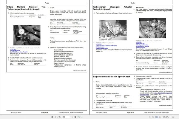
Intake Manifold Pressure Test-Turbocharger Boost—9.0L Stage II
Turbocharger Wastegate Actuator Test—9.0L Stage II
Engine Slow and Fast Idle Speed Check
Radiator Temperature Differential Test
Electrical System
System Information
Electrical Diagram Information
Electrical Schematic Symbols
System Diagrams
Fuse and Relay Specifications
System Functional Schematic, Wiring Diagram, and Component Location Master Legend
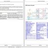
System Functional Schematic
JDLink™ System Functional Schematic—MIG/GTT
JDLink™ System Functional Schematic—MTG/SAT
Engine Interface Harness (W9) Component Location—9.0L
Engine Interface Harness (W9) Wiring Diagram
Front 6WD Harness (W10) Component Location
Front 6WD Harness (W10) Wiring Diagram
Rear 6WD Harness (W11) Component Location
Rear 6WD Harness (W11) Wiring Diagram (S.N. —667937)
Rear 6WD Harness (W11) Wiring Diagram (S.N. 667938— )
Heater and Air Conditioner Harness (W12) Component Location
Heater and Air Conditioner Harness (W12) Wiring Diagram
Radio Harness (W13) Component Location
Radio Harness (W13) Wiring Diagram
Cab Roof Harness (W14) Component Location
Cab Roof Harness (W14) Wiring Diagram
Cab Interior Harness (W15) Component Location—6WD
Cab Interior Harness (W15) Wiring Diagram—6WD
Cab Interior Harness (W16) Component Location—Non 6WD
Cab Interior Harness (W16) Wiring Diagram—Non 6WD
Left Front Motor Speed Sensor Harness (W17) Component Location—6WD
Left Front Motor Speed Sensor Harness (W17) Wiring Diagram—6WD
Right Front Motor Speed Sensor Harness (W18) Component Location—6WD
Right Front Motor Speed Sensor Harness (W18) Wiring Diagram—6WD
Blade Impact Harness (W19) Component Location
Blade Impact Harness (W19) Wiring Diagram
Turn-Tail-Stop Light Harness (W20) Component Location
Turn-Tail-Stop Light Harness (W20) Wiring Diagram
Resistor Harness (W21) Component Location
Resistor Harness (W21) Wiring Diagram
Drive-Turn Light Harness (W22) Component Location—Right Front
Drive-Turn Light Harness (W22) Wiring Diagram—Right Front
Drive-Turn Light Harness (W23) Component Location—Left Front
Drive-Turn Light Harness (W23) Wiring Diagram—Left Front
Steering Angle Sensor Harness (W24) Component Location—6WD
Steering Angle Sensor Harness (W24) Wiring Diagram—6WD
Front Platform Harness (W25) Component Location
Front Platform Harness (W25) Wiring Diagram
Rear Platform Harness (W26) Component Location
Rear Platform Harness (W26) Wiring Diagram (S.N. —636526)
Rear Platform Harness (W26) Wiring Diagram (S.N. 636527—667937)
Rear Platform Harness (W26) Wiring Diagram (S.N. 667938— )
Rear Camera Harness (W27) Component Location
Rear Camera Harness (W27) Wiring Diagram
Engine Harness (W29) Component Location—9.0L Tier 3/Stage IIIA
Engine Harness (W29) Wiring Diagram—9.0L Tier 3/Stage IIIA
Engine Harness (W30) Component Location—9.0L Tier 2/Stage II
Engine Harness (W30) Wiring Diagram—9.0L Tier 2/Stage II
Fan Door Harness (W31) Component Location
Fan Door Harness (W31) Wiring Diagram
Engine Work Light Harness (W33) Component Location
Engine Work Light Harness (W33) Wiring Diagram
Midstructure Harness (W34) Component Location
Midstructure Harness (W34) Wiring Diagram
Midstructure Harness (W34) Wiring Diagram (S.N. 667938— )
Transmission Harness (W35) Component Location
Transmission Harness (W35) Wiring Diagram
Tilt Console Harness (W36) Component Location—Standard Controls
Tilt Console Harness (W36) Wiring Diagram—Standard Controls
Tilt Console Harness (W37) Component Location—EH Controls
Tilt Console Harness (W37) Wiring Diagram—EH Controls
Electrohydraulic (EH) Main Cab Harness (W38) Component Location
Electrohydraulic (EH) Main Cab Harness (W38) Wiring Diagram
Electrohydraulic (EH) Main Frame Harness (W39) Component Location
Electrohydraulic (EH) Main Frame Harness (W39) Wiring Diagram
Electrohydraulic (EH) Draft Frame Harness (W40) Component Location
Electrohydraulic (EH) Draft Frame Harness (W40) Wiring Diagram
JDLink™ System Harnesses Component Location—MIG/GTT
JDLink™ System Harnesses Component Location—MTG/SAT
JDLink™ System Wiring Diagrams—MIG/GTT
JDLink™ System Wiring Diagrams—MTG/SAT
Electrohydraulic (EH) Integrated Grade Control (IGC) (W43) Component Location
Electrohydraulic (EH) Integrated Grade Control (IGC) (W43) Wiring Diagram
Right Armrest Harness (W44) Component Location
Right Armrest Harness (W44) Wiring Diagram
Left Armrest Harness (W45) Component Location
Left Armrest Harness (W45) Wiring Diagram
Battery Disconnect Harness (W60) Component Location
Battery Disconnect Harness (W60) Wiring Diagram
Circuit Breaker Harness (W61) Component Location
Circuit Breaker Harness (W61) Wiring Diagram
Flex Load Controller (FLC) Harness (W62) Component Location
Flex Load Controller (FLC) Harness (W62) Wiring Diagram
Starter Harness (W63) Component Location
Starter Harness (W63) Wiring Diagram
Glow Plug/Intake Air Heat Relay Harness (W64) Component Location
Glow Plug/Intake Air Heat Relay Harness (W64) Wiring Diagram
License Plate Harness (W65) Component Location
License Plate Harness (W65) Wiring Diagram
Rear View Camera Display Harness (W67) Component Location
Rear View Camera Display Harness (W67) Wiring Diagram
Sub-System Diagnostics
Controller Area Network (CAN) Theory of Operation
Start and Charge Circuits Theory of Operation
Transmission Control Unit (TCU) Circuit Theory of Operation
Engine Control Unit (ECU) Circuit Theory of Operation
Flex Load Controller (FLC) Circuit Theory of Operation
Advanced Display Unit (ADU) Circuit Theory of Operation
Six Wheel Drive (6WD) Controller Circuit Theory of Operation
Park Brake Circuit Theory of Operation
Auxiliary Valve Controller (AVC) Circuit Theory of Operation
Hydraulic Valve Controller (HVC) Circuit Theory of Operation
Monitor Operation
Advanced Display Unit (ADU)—Service Mode
Advanced Display Unit (ADU)—Clear Codes
Advanced Display Unit (ADU)—Show/Hide Main Menu
Advanced Display Unit (ADU)—Enable Options
Advanced Display Unit (ADU)—Tire Size
Advanced Display Unit (ADU)—Fan Speed
Advanced Display Unit (ADU)—Articulation Cal
Advanced Display Unit (ADU)—Steering Cal
Advanced Display Unit (ADU)—GP Auxiliary Valve Flows
Advanced Display Unit (ADU)—GP Auxiliary Control Setup
References
Cross Slope Diagnostics
Flex Load Controller (FLC) Outputs
Service ADVISOR™ Application
Service ADVISOR™ Connection Procedure
Reading Diagnostic Trouble Codes (DTC) With Service ADVISOR™ Application
JDLink™ System Identification
JDLink™ Connection Procedure—If Equipped
Transmission Control Unit (TCU) Calibration
6WD Controller Calibration (If Equipped)
CAN Circuit Testing
Electrical Component Specifications
Alternator Test
Hydraulic Pump Pressure Sensor Test
Transmission Control and Park Brake Lever Test
Park-Not Neutral Gear Position Switch Module (S6) and Forward/Reverse Switch Module (S5) Test
Output Shaft Speed Sensor Test
Inching Pedal Module Test
Lower Windshield Wiper Proximity Switch Adjustment and Installation
Electrical Component Checks
Articulation Sensor Linkage Adjustment (Rear Steer)
Electrohydraulic Valve Calibration Procedure
Articulation Sensor Calibration Procedure
Steering Angle Sensor Calibration Procedure
Park-Not Neutral Gear Position Switch Module (S6) and Forward/Reverse Switch Module (S5) Remove and Install
Controller Remove and Install
Steering Angle Sensor Remove and Install
Replace Weather Pack™ Connector
Install Weather Pack™ Contact
Replace DEUTSCH® Connectors
Replace DEUTSCH® Rectangular or Triangular Connectors
Install DEUTSCH® Contact
Replace (Pull Type) Metri-Pack™ Connectors
Replace (Push Type) Metri-Pack™ Connectors
Replace Connectors
Install INCH Contact
Repair 32 and 48 Way CINCH® Connectors
Six Wheel Drive (6WD)
Theory of Operation
6WD System Operation
6WD Pump and Displacement Control Operation
6WD Forward Operation
6WD Pump and Motor Flushing Pump Operation
6WD Charge Circuit Operation
Flushing Valve and Operating Charge Pressure Regulating Valve Operation
6WD Circuit Relief and Make-Up Valve Operation
6WD Engagement Manifold Operation
6WD Motor Operation
6WD Wheel Operation
6WD Precision Mode Operation
6WD Inching Mode Operation
Diagnostic Information
6WD System Schematic
6WD System Component Location
No Front Wheel Motion (Both Wheels)
No Front Wheel Motion During Inching Operation (Both Wheels)
No Front Wheel Motion (One Wheel)
Intermittent or Erratic 6WD Operation
6WD Charge Pressure Indicator Light On
Hydraulic Oil Filter
Hydraulic Oil Temperature Indicator Light On
6WD System Oil Temperature Too Hot (6WD oil temperature indicator light on)
Low Torque (One Wheel)
Low Torque (Both Wheels)
Wheel Overspeed (One Wheel)
Operates in Low Speed Only (One Wheel)
Operates in High Speed Only (One Wheel)
Wheel(s) Will Not Stay in Neutral
Operates in One Direction Only
Wheels Rotate Opposite Each Other
6WD Will Not Calibrate (No Diagnostic Trouble Codes)
Adjustments
6WD Start-Up Procedure
6WD Pump Control Neutral Adjustment
Tests
Avoid High-Pressure Fluids
6WD Oil Warm-Up Procedure
6WD Planetary Brake Leakage Test
6WD Neutral Charge Pressure Test
6WD Neutral Charge Pressure Regulating Valve Test
6WD Operating Charge Pressure Regulating Valve Test
6WD Neutral Charge Pressure Balance Test
6WD Motor Leakage Test
Pressure Override Valve and 6WD Circuit Relief and Make-Up Valve Test
6WD Motor Flushing Pump Relief Valve Test
6WD Charge Pump Flow Test
6WD Engagement Solenoid Valve Test
Hydraulic Oil Cooler Bypass Valve Pressure Test
Power Train
Theory of Operation
DF230 Transmission Operation
Differential Lock Operation
Internal Park Brake Operation
Rear Axle and Tandem Operation
Diagnostic Information
Power Train Schematic
Power Train Component Location
Transmission Overfills With Oil
Transmission Slippage
Machine ‘Jumps” When Inching Pedal Engaged
Machine Lacks Power Or Moves Slow
Transmission Shifts Too Slow (Machine Stops When Changing Gears Under Load)
Transmission Shifts Too Quickly
Machine Will Not Move In Any Gear and Park Brake Indicator Light Is On (No Load Put On Engine When Shifted Into Gear)
Machine Will Not Move (Load Put On Engine Or Engine Stalls When Shifted Into Gear)
Low Pressure In Different Gears Using Same Proportional Solenoid Valve
Machine Creeps In Neutral (Load Put On Engine When Service Brakes Are Applied)
Machine Creeps In Gear With Inching Pedal Fully Depressed
Transmission System Overheats
Transmission Control and Park Brake Lever Does Not Move Freely
Excessive Transmission Noise (Under Load or No Load)
Transmission Engages In a Gear, but Not Gear Selected
Transmission Fails To Change Gear From First Gear Selected
Transmission Faults To Neutral
Excessive Machine Vibration
Erratic Transmission Oil Pressure
Excessive Oil Pressure
Low Oil Pressure In All Gears
Low Pressure In One Gear But Correct In Other Gears
Transmission Breather Oil Leakage
Filter Or Filter Oil Lines Blow Out
Low Lube Pressure In Some Gears But Correct In Other Gears
Excessive Lube Pressure In Some Gears But Correct In Other Gears
Low Transmission Cooler Inlet Pressure And Lube Pressure
Park Brake Engages While Vehicle Is Moving
Park Brake Will Not Release
Park Brake Will Not Hold
Park Brake Overheats
Park Brake Noisy
No Differential Lock Operation
Differential Lock Slippage
Excessive Differential and/or Axle Noise
Tests
Differential Oil Warm-Up Procedure
Differential Lock Valve Pressure Test
Differential Oil Cooler Flow Test
Differential Oil Cooler Relief Valve Pressure Test
Park Brake Release Pressure Test
Hydraulic System
Theory of Operation
Hydraulic System Operation
Hydraulic Pump Operation (S.N. —667937)
Hydraulic Pump Operation (S.N. 667938— )
Hydraulic Fan Pump Operation
Hydraulic System Manifold Operation
Control Valve Operation—Standard Controls
Control Valve Operation—EH Controls
Hydraulic Oil Filter Operation
System Relief Valve Operation
Circuit Relief Valve Operation
Service Brake Valve Operation
Service Brake Accumulator Operation
Hydraulic Fan Drive Operation
Steering System Operation
Steering System Operation—EH Controls
Load Sense Operation With All Functions in Neutral
Load Sense Operation With One Function Activated
Load Sense Operation With Multiple Functions Activated
Wheel Lean, Articulation, Circle Side Shift, Blade Pitch, and Blade Side Shift Valve Operation
Circle Rotate Valve Operation
Saddle Locking Pin Valve Operation
Blade Lift and Auxiliary Valve Operation
Blade Impact Absorption System Operation
Circle Drive Gearbox Operation-Without Slip Clutch
Circle Drive Gearbox Operation-With Slip Clutch
Hydraulic Oil Cooler Bypass Manifold Operation
Diagnostic Information
Hydraulic System Schematic
Hydraulic System Schematic—EH Controls
Hydraulic System Component Location
Hydraulic System Component Location—EH Controls
No Hydraulics
Hydraulic System Overheats
Slow Hydraulic Functions
Hydraulic Function (or Pump) Makes ‘Chattering” Noise
Pump Appears To Be Stuck At Minimum Displacement
Pump Appears To Be Stuck At Maximum Displacement
Function Moves Too Fast
Function Drifts Down
Excessive Effort to Move Function Control Lever
Individual Function Is Slow (Cycle Time Checked Slow)
Slow or Hard Steering
No Steering
Erratic Steering
Excessive Steering Wheel Turns to Steer Machine
Wheels Move After Steering Wheel Stopped
Excessive Vibration of Steering Wheel
Steering Wheel Kickback
Poor or No Brakes (Steering and Hydraulic System Operation Normal)
Aggressive Brakes or Brakes Lock Up
Brakes Drag
Brakes Chatter or Noisy
Delay in Braking
Hydraulic Fan Does Not Reach Full Speed
Hydraulic Fan Runs At Full Speed Only
Hydraulic Fan Does Not Spin
Hydraulic Fan Will Not Reverse Direction
Tests
Fluid Sampling Procedure—If Equipped
Hydraulic Test Port Location
JT02156A Digital Pressure/Temperature Analyzer Kit Installation
JT07148 Digital Hydraulic Flowmeter Tester
Hydraulic Oil Warm-Up Procedure
Vacuum Pump Installation
Hydraulic Pump Standby Pressure & Load Sense Standby Pressure Test
Load Sense Relief Valve & Pump Relief Test
Load Sense Shuttle Valve Isolation Test—Standard Controls
Load Sense Shuttle Valve Isolation Test—EH Controls
Hydraulic Pump Leakage Test
Hydraulic Pump Flow Test
Service Brake Valve Pressure Test
Service Brake Accumulator Precharge Test
Service Brake Pressure Switch Test
Service Brake Valve Leakage Test
Hydraulic Cylinder Drift Test
Hydraulic Cylinder Leakage Test
Rotary Manifold Leakage Test
Steering System Leakage Test
Service Brake Accumulator Inlet Check Valve Leakage Test
Blade Impact Absorption Accumulator Charge Pressure Test
Blade Impact Absorption Accumulator Hydraulic Discharge Procedure
Secondary Steering Accumulator Charge Pressure Test
Blade Lift Relief Valve Test
Circuit Relief Valve Test—Midmount Scarifier
Saddle Locking Cylinder Pressure Reducing Valve Test
System Relief Valve Pressure Test
Hydraulic Fan Pump Pressure Test
Hydraulic Fan Motor Speed Test
Hydraulic Fan Pump Flow Test
Hydraulic Fan Motor Case Drain Test
Heating and Air Conditioning
Theory of Operation
Air Conditioning System Cycle Of Operation
Diagnostic Information
Air Conditioner and Heater Component Location
Diagnose Air Conditioning System Malfunctions
Air Conditioning System Does Not Operate
Air Conditioner Does Not Cool Interior of Cab
Air Conditioner Runs Constantly, Too Cold
Diagnose Heater System Malfunctions
Heater System Does Not Operate
Heater Does Not Warm Interior of Cab
Interior Windows Continue to Fog
Adjustments
Heater Control Cable Adjustment
Defog-Defrost Cable Adjustment
Tests
Refrigerant Cautions and Proper Handling
Air Conditioner and Heater Operational Checks
Refrigerant Leak Test
Air Conditioner Compressor Clutch Test
Air Conditioner High/Low Pressure Switch Test
Air Conditioner Freeze Control Switch Test
Heater Blower Switch Test
Heater Blower Resistor Test
Heater Blower Motor Test
R134a Air Conditioning System Test
Operating Pressure Diagnostic Chart
Page Number

REALEASE :
REALEASE :

REALEASE :
12.09.2021
REALEASE :
12.09.2021

REALEASE :
12.28.2021
REALEASE :
12.28.2021
REALEASE :
13.05.2022
REALEASE :
13.05.2022

REALEASE :
REALEASE :
REALEASE :
13.05.2022

REALEASE :
12.09.2021
REALEASE :
12.09.2021
 Automotive - Heavy Equipment - Truck & Bus - Forklift - Crane

